Tuesday, December 26, 2023

Stacking PCBs

To have enough room on the voice card PCB, I think I will have to stack at least the Juno and Moog filter PCBs on top of eachother. But I don't want to pay for double sided boards and I don't want to solder the connectors myself.

Here are some options that I've come up with. All of them requires the filter PCBs to be mounted with their parts facing downwards:

This is probably the best option. It has a clearing of 5mm between the middle and lower board, and 4.4mm between the top and middle. Further more, we can increase this to 5.9mm by not covering the whole connector of the middle board, this is necessary as the Moog board has some 5.7mm high capacitors.

It also has the smallest possible space needed on the bottom board, 1.28cm (at least if parts on the bottom board are not higher than 2.5mm). 


It would be possible to put the middle board closer to the bottom, but this only leaves 2.5mm for parts and we need more space without parts to be able to slide the card in. It does leave a lot of space between the middle and top though.

This is a slightly more stable version of the first, as it uses a double sided connector on both cards. This will however steal more than twice the space from the bottom board as we need a lot of space to slide the card into place.

Tuesday, November 28, 2023

New LED-ring try - great success!

Today I laser cut some new cells for the led ring, the ones I posted about before the "pro" version arrived.

I first had a go with birch plywood. The thinnest version (0.3mm walls) broke apart but the others looked great.


Plywood - first has rectangular cells with a minimum of 0.3mm between them (before cutting, the kerf makes it thinner). Second has 0.5mm between wedged cells and the final one has 0.7mm. This is what I went with for the rest of the cuts.

I then moved to white acrylic, which was the one I had my hopes up for. The first try was a disaster, the cutout got too hot and melted back with the rest, and (i think) gas got trapped under the acrylic, starting small fires that burned away parts of the plastic.

Next up, I tried engraving. I had to engrave 30 times (!) to get through, and even then the hole on the back was much narrower than the one in front, so this was both not good enough and too time consuming.

Finally I turned down the power and speed up, from 100 power/20 speed to 90 power/40 speed. I also split the job into 10 parts, with each part only having the slits that were at 90 degree angles from one another, to keep the heat down. This worked wonders!

Left: First version, full power. This is the underside, showing where it burned.
Center: The engraved version, from the bottom side. The top looked like the two others.
Right: A pretty perfect version, cut in 10 jobs to let everything cool down a bit.


Then, almost as an afterthought I did a black MDF version, and also some thick black paper ones to put on top.

Left: LED PCB, black MDF and black paper with diffuser on the back


When I got back home today, I set up a small test rig with a single LED connected to 5V through a 330Ohm resistor. I also put some white translucent paper ("matpapir", close to baking paper) behind the black paper to use as a diffuser.

Baking paper used as diffuser

First try was the white acrylic. I had seen earlier that the sun shone through parts of it so I wasn't so sure about it anymore - and that turned out to be correct. The light leaks through the wall into the next cell.

Three layers stacked

The bleeding is very visible already

 
The results are very bad even with the diffuser

So the second try was the black MDF. It worked great! It's hard to show in the photos just how good it actually looks, but this is near perfect. When I bumped up the voltage to 8.8V it looked even better.

This! This is almost magical. No bleeding and a very visible red wedge. This is actually under strong white light too, so it's just amazingly good.

Finally, I put the red lense over as I did on my previous trial and it looks good. I do think the 3mm red acrylic is a bit too thick though, it gets a bit hard to see everything from an angle. I have to think about other solutions to this.

With the red lense. The unlit segments are a bit too visible for my taste. I think using a "smoked" diffuser would improve this. It isn't as visible in real life though.

my only concern is this - the red lense is 3mm thick, so when looking at the dial at an angle it's a bit hard to see the segment.

It looks even better with a higher current, 8.8V through 330Ohm in this test.


Sunday, November 26, 2023

Led ring disassembled

Today the Aliexpress led ring arrived (on a sunday! and after only 10 days!).

It is actually much smapper than I anticipated. 


I could clearly see that there was some kind of film on top of it, so I gently tried to lift it. It came right off, and lo and behold - it's the exact solution I've been thinking of! The film is about 0.15mm thick. The white ring is 3mm.


Inside, there are holes all the way down to the PCB, with some kind of surface mount diodes. The holes have white edges but the front is black. It looks very good. If I'm able to cut similar holes I have a good chance of making this work :-D


Sunday, November 19, 2023

LED ring - alternative controllers

Reddit user DasBraadwurst is making a very cool led ring for mounting on guitar pedals. He showed a screenshot of his circuit and it seemed to have a very small controller on it. I inquired about it and he was kind enough to tell me: It's the Lumissil IS31FL3728 I2C LED matrix driver. 

 It measures 4 x 4 mm so it's perfect for my led dials. It drives up to 8 x 8 leds, so it's still a bit of a waste to use one per dial, and it does have an issue with addressing (it can only be set to four different ones) so I need to figure out if it is possible to switch address dynamically and just "enable" the one I need to write to (Address is set by connecting the address pin to Vcc/GND/SDA/SCL. Perhapsone could switch between vcc and gnd?)

The chip is available at jlcpcb (C2678860) at a price of $0.62 in quantities of 100, though right now they only have 80 in stock: 

https://jlcpcb.com/partdetail/Lumissil-IS31FL3728_QFLS2TR/C2678860

Interestingly enough, jlcpcb as another matrix led driver available, the IS31FL3729 (C2940549), which is a 16 x 8 chip - but they have more in stock and it is actually cheaper ($0.58 @ 100), so perhaps it's worth giving a try.

For comparison, the STP16CPC26 constant current led driver shift register is more expensive ($0.73 @ 100). However, it IS less specialized, meaning it can be replaced if replaced. With the IS31 I would have to come up an I2C version with similar addressing.

Thursday, November 16, 2023

LED rings - the missing post

More than three years ago I did a lot of prototyping of LED dials/rings that I will use to indicate the position of the endless potentiometers on my synth.

I can however only find a couple of posts here about it, one is from the early prototyping of a diffuser lense, and the other one from when I sent the PCB to production - but then it ends.

I did however take some photos and videos of everything, so as I just picked up the idea again I thought it would be nice to post about it.

A diffuser test with a single normal led. The diffuser consists of two layers, one with an engraved circle that diffuses the light, and one where the center has been cut out and a slit has been made for each cell, to prevent light from bleeding between cells. It worked impressingly well for a first try.


The LED ring PCB, 31 + 1 LEDs in a 270 degree arc (to match a normal potentiometer)

Diffuser prototype. Here I've engraved a ring, and then cut slits in an attempt to keep light leakage between elements to a minimum

A similar version, but here the engraving is on a separate piece of acrylic so we have two layers.

Not entirely sure about this one, but I think I've engraved both slits and ring, but engraved the slits deeper.

Same as above but with the additional second layer.


Not sure what combination this is but it's starting to look good

My text for this says "cut 3mm outside". I did some versions where i had an additional cut outside or inside to prevent even more light bleeding

I even did a version where I put tiny black paper dividers between each cell. It worked fairly well but was extremely impractical and would take ages for the number of pots I need.

I tried cutting a mask in multiple layers of thick paper to prevent light bleeding under the acrylic.

After all these white diffuser trials, I decided to try out red acrylic instead. That worked wonders!

I actually really like this look. The dots are clearly visible but still cool. And the background gets rather dark as the PCB is green, so I actually think it looks better when turned off than the next version. It is also the simplest to produce.


This is also a really good version. I think it is a combination of the best cell-and-engraving version with the red lense, possibly with black cutouts

Here are some videos of the ring in action:


All in all, I was rather satisfied with the result, so I decided to move on to other things.

Then, today, a colleague sent me a link to this video:

https://www.youtube.com/watch?v=tHL4RYGSvg4

Finally, someone has made a good enough commercial version of a led ring:


It is prohibitively expensive though, around $10 per ring! 

https://www.aliexpress.com/item/1005005361069637.html

But this got me thinking - how do they actually make those rings? Why does it not bleed between cells, and more importantly - how can I do something similar?

So now I'm back to the idea of cutting a mask again. The Bargraph ring is 3.4mm high, so I will try cutting a 3mm high mask out of black MDF or even acrylic. I am not sure how detailed I can get it so i will try some various versions - from 0.3 to 0.7mm walls between cells, and both engraving and cutting - engraving takes much longer but also uses lower temperatures so it may be possible to get a thinner wall.

Mask for cutting/engraving 3mm thick material


I then have a few options. I can try adding a diffuser on top, and then a red layer on top of that, that would probably look quite nice. 

 Or, I could try placing the mask over the leds and fill the holes with resin, and then sand the top to get either a smooth or diffuse finish. Using a clear resin would give me lightpipes up to the surface, possibly with some internal reflection to even out the light. I could also try translucent resin, or even red resin.

I think this has some chance of looking good, and it would also be fun to try out. I will start out with the laser cutting and see how it works out.


Saturday, November 11, 2023

JP6 Resonance CV conversion

 I'm trying to use a linear CV to control the resonance, but without the exponential converter of the original circuit.

I've simulated the Jove circuit and got this response:


My linear CV has this response

Linear response, indicating the max/min input CVs needed to get same i_abc range as the Jove one.


To get the same control curve, I need to map the linear response in my own code.

But what shape should it have?

Here is a graph showing what input voltages will give the same I_abc as the Jove version:

As we can see, it is the same curve as the I_abc curve for the jove, but dropping instead of rising as our CV is inverted.

I tried with a logarithmic curve but it doesn't quite have the correct shape. Instead, an exponential curve but mirrored around 0 would do the trick, I'll see if I can add that to my generator.

Wednesday, November 8, 2023

UI update

I've been thinking a bit about the UI lately, and especially how to control the LED dials. I've previously found some nice constant current LED driver mux'es. They have 16 channels, which I can use to multiplex the (up to) 31 diodes of a led dial.

But 16 channels may be split into 8 x 8 = 64 channels, meaning I can drive at least TWO dials from a single controller.

Thus, I went back to see if I could group dials a bit smarter so I can put two and two dials on a PCB with one shared multiplexer. Also, it would be cool if I could make "modules" for the UI so I can make multiple copies of various boards, which is significantly cheaper than one-offs.


Here is a restructuring of the left hand side, this made me rethink the structure and ended up actually solving some issues I had with the natural flow - now I have sources top/left, then the source mixer and finally fx. Much better.

Before restructuring


After restructuring - now fx pots align vertically, and LFO stuff aligns with clock/arp. I've also managed to squeeze in an additional LFO pot and some buttons, and replaced the LFO selector switches and made a better (two sided) shape selector.

As for other modules: I will try to make a PCB that can work with both DCO/VCOs and Filters, though the SVF slope selector is a bit of an unsolved case:


I will probably replace the Ext CV/Wheel/LFO/Kbd buttons with pots, and space them the same as for the filters

I will have to change the size of the top pots to match the oscillators. The Slope selector is a bit anoying, perhaps I can make boards that break apart making it possible to remove the selector bit


The envelopes are of course identical, except for an additional button on Env 3:


Also, the output mixer and pan/fx send modules are similar and could maybe even use the dual led rings from the source mixer/left side


There are still quite a few special modules, like everything in the lower part of the screen, but every little simplification helps!

Latest version of the front panel


Thursday, October 12, 2023

DCO bug


I get some clickling when changing pitch (when not using an envelope)

This shows what is going on - when the new pitch is lower, the timer is not properly updated so it resets the pulse too early, before the wave has reached its maximum. Perhaps this could be fixed by simply letting the wave run until it is reset by the comparator?

Sunday, September 24, 2023

DG412 bus mixer

 Here is my initial design:


All VCAs are non-inverting and the bus summers are inverting.


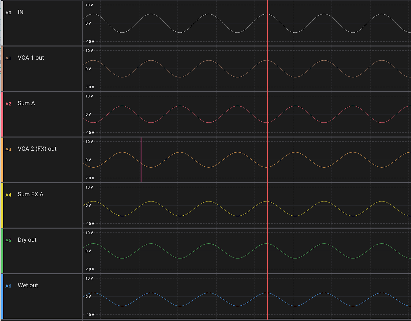
These are the phases at various points


VCA 1 output: in phase, OK

Sum A: inverted: OK,

VCA 2: receives inverted input and outputs inverted, OK.

Sum FX A: in phase, OK

Dry out: inverted, OK

Wet out: in phase, OK

So all are as expected. But there's a problem! Dry and wet out are supposed to be mixed, but they are not in phase!

To fix this, we have two options

- Invert all input VCAs (but leave the wet/dry). That way, Sum A and Sum FX A are in phase

- Invert dry out VCA so bot dry and wet are in phase.

The first option is the more "correct", I just need to see if this works well.

Option 1:


VCA outputs are now inverted, but Sum A, Sum FX A, Wet and dry are in phase. This makes the module easier to think about as we don't need to know what is going on inside, phase in is always phase out.


Option 2:


Only Dry out VCA is changed (now inverts). Sum A is still inverted but now wet and dry are both in phase.

CV input

As my CV is 0-5V, but the AS3364 wants 0-2V, I wanted to test if there was any difference between the CV responses when the CV was

1) a direct output from an op amp buffer (actually, a resistor divider tapped at it's center but then buffered with a non-inverting op amp)

2) tapped from the center of a resistor divider (0-5v connected to a 33k + 22k to gnd, effectively making the CV 0-2V)


I used a 0-5V triangle wave, buffered it twice and sent one to a resistor divider with an op amp buffer after it, connected to the CV input of one AS3364 cell, and the second to a resistor divider, tapped at the center and connected to the CV input of a second cell.

I then connected a 1.8V (150k + 27k between 12V and GND) to the signal inputs of the AS3364.

As I've seen earlier, the CV response is not completely linear, but I could see no difference between the two versions. My conclusion is thus that the unbuffered CV version is good enough.


CV Response

As on all the other AS3364 modules, I use a resistor divider (33k + 22k) to divide down 5V to 2V on the CV input.

I got curious about whether or not buffering this CV made any difference so I breadboarded both versions, turns out it does NOT make a difference meaning just two resistors without an op amp buffer works just fine.