I've been wondering for a long time what to do with the FX section of the XM8. I want something that isn't considered "cheap" or "tacky". I've scrolled passed the FV-1 at Banzai Music multiple times, but I thought that it seemed a bit limiting with its 8 built in programs, and it is also SMD which I try to avoid now that I'm unable to solder.
Today it popped up again when searching for "multi effects IC". I had a closer look and realised it is actually considered very good. There are open source effects available for it and it is programmable. The only limitation is that the programs have to reside on an EEPROM and that you can have only 8 of them.
BUT - the FV-1 accesses the EEPROM through I2C, which means that one can emulate the EEPROM using a MCU, and thus have full control over what it loads. That means we can do "in-circuit programming", or rather, have full flexibility and load as many progs as you want.
Here are a few links:
An article about the FV-1: https://reverb.com/news/fv-1-chip-history-5-pedals
Open source programs: https://github.com/mstratman/fv1-programs
Free programs from Spin Semiconductor: http://www.spinsemi.com/programs.php
A fully populated board, making testing easier for me: https://www.electro-smith.com/electro-boards/fv-1-dsp
Monday, July 27, 2020
Thursday, July 23, 2020
Quick thought on bitcrusher
The bitcrusher works in two ways - it reduces sample rate and it reduces the bit resolution.
A good quality audio DAC circuit needs a reconstruction filter after the DAC to remove unwanted high frequencies ( >20kHz). When sample rate is reduced, this filter's cutoff must also be reduced to approx twice the sampling rate to keep the quality.
BUT - in a bitcrusher, don't we actually WANT the coarseness caused by not filtering the signal perfectly? I assume so. This has to be tested.
I will try building a bitcrusher with a simple ADC->MCU->DAC->static LPF and see.
https://en.wikipedia.org/wiki/Bitcrusher
PCM player, DAC, PIC32MX and I2S
I have multiple options for a wave player/sampled attack/wavetable oscillator.
- I can add a DAC to the Voice controller and control it directly there - using a I2S Audio DAC will probably give a very high audio quality
- I can make a separate board with the same DAC, an extra MCU and external memory
- I can try to use the DCOs - they already have a 16bit DAC and I think I have exposed enough SPI pins to make it possible to access external SPI memory. This is the cheapest option but the sound quality must be tested.
In any case, when making the Voice board I should leave room for an optional wave card. It doesn't need its own VCA as the DAC should be good enough for volume control as well.
PIC32 and I2S Dac
It seems most Audio DACs these days use I2S for communicating with the host. The PIC32MX (and other low-end PIC MCUs) don't have I2S support built in, but here is something that seems to make it work:
https://www.aidanmocke.com/blog/2018/11/22/i2s/
https://hackaday.io/project/28965-pic32mx-music-box-with-fm-synthesis-and-i2s-dac
https://tutorial.cytron.io/2017/08/13/i2s-pic32mxmz-introduction/
DAC in general
DACs need a reconstruction filter to remove unwanted frequencies. Here is an example that claims to be good:
https://www.analogfilters.com/high-quality-reconstruction-lowpass-filter-for-digital-audio/
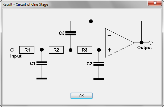
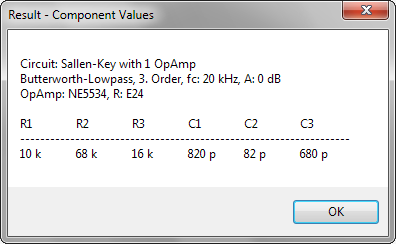
https://www.softwaredidaktik.de/active-filters/download/
- I can add a DAC to the Voice controller and control it directly there - using a I2S Audio DAC will probably give a very high audio quality
- I can make a separate board with the same DAC, an extra MCU and external memory
- I can try to use the DCOs - they already have a 16bit DAC and I think I have exposed enough SPI pins to make it possible to access external SPI memory. This is the cheapest option but the sound quality must be tested.
In any case, when making the Voice board I should leave room for an optional wave card. It doesn't need its own VCA as the DAC should be good enough for volume control as well.
PIC32 and I2S Dac
It seems most Audio DACs these days use I2S for communicating with the host. The PIC32MX (and other low-end PIC MCUs) don't have I2S support built in, but here is something that seems to make it work:
https://www.aidanmocke.com/blog/2018/11/22/i2s/
https://hackaday.io/project/28965-pic32mx-music-box-with-fm-synthesis-and-i2s-dac
https://tutorial.cytron.io/2017/08/13/i2s-pic32mxmz-introduction/
DAC in general
DACs need a reconstruction filter to remove unwanted frequencies. Here is an example that claims to be good:
https://www.analogfilters.com/high-quality-reconstruction-lowpass-filter-for-digital-audio/
https://www.softwaredidaktik.de/active-filters/download/
Sunday, July 19, 2020
Oscillator UI
Just an initial sketch, let user morph between waveforms, and select what waveforms should be included in the morph:
 By selecting only certain waveforms for morphing means one can start a morph by a modulation source at a different point than sine.
How to select various stuff for modulation by various sources needs to be investigated.

How to select various stuff for modulation by various sources needs to be investigated.
Friday, July 17, 2020
Distortion circuit mostly ready for production
I've finished v1 of the distortion circuit PCB:


I still have to double check the schematics, I've done so many silly errors lately...
The board has switchable soft/hard clipping, and CV adjustable distortion and output gain.
Little/slim phatty distortion/overload
Before I send this one to production, I will breadboard and try out the distortion circuit from the little phatty:

It looks fairly similar, but the output, labeled audio_sum, is actually connected to a point BEFORE the input, labeled mixer_out here. This means it actually feeds the result back to the start, not only distorting it (there is only buffer and voltage divider between though). Also, the overload_cv controls an additional output VCA located after the filter. I can't tell from the circuit diagram what the gain / level is at various points of the circuit so I will simulate this.

Wednesday, July 8, 2020
VCO testing
I've tested my CEM3340 VCO with waveshaper. It works fairly well. It has one major flaw:
Triangle frequency drops when changing pw from 50/50 to 90/10. This was expected for the Cem PWM, but it happens, and is even more pronounced, with my own pwm! I have tried buffering the supply lines (+/-15v) but it doesn't help
In general it is extremely sensitive to voltage changes, so my breadboard isn't exactly the ideal test platform. But it is annoying none the less.
Other than that:
- All waveforms work fine
- Linear FM works fine
- Hard sync works fine
- Cem Hard Sync works fine, but only with a 1nF cap in series with the input signal. Normal hard sync works without this (prob. because it already has a 220pF series cap) but also works WITH.
 |
| Saw wave, CEM Hard sync |
 |
| Saw wave, normal hard sync |
 |
| Saw wave, CEM Soft sync? Doesn't seem to work very well, not sure how it is supposed to work really (noone seems to know :-D) |
 |
| Triangle wave, CEM Hard sync |
 |
| Triangle wave, normal hard sync |
 |
| Triangle wave, CEM Soft sync. Again, it looks like CEM hard sync. Not sure what to expect. |
Friday, July 3, 2020
Ring modulator tested, seems to be working
I tested my version of the yusynth.net ring modulator today.
I tried connecting VCAs on the inputs but it doesn't seem very necessary, they affect the signal almost exactly like the output VCA does, so a single output vca will do fine.
1uF input caps seem like a good idea, perhaps an output cap too
I used a 500R pot in place of a 200, looks like I got away with it.
Trimming is done as described in the picture (same as on yusynth.net):

Thursday, July 2, 2020
JP6 Filter - error on PCB
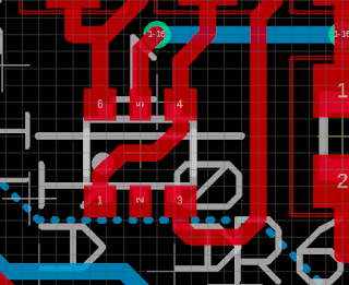
I have managed to mess things up with the JP6 filter as well. I've drawn one single trace using layer 97 - info instead of the trace, so the left base of the cutoff CV expo converter is not connected to GND.
This is possibly the single worst place on the whole board to err, as the transistor IC is soooo tiny:


Update 7th of July: I found a second error, R22 should be connected to the negative mixing point of the resonance OTA (IC4A), not the junction between R19 and R19 (pin 1 of IC2A).
After fixing this, and realising I had used a 100k instead of a 10k resistor between the VCA CV and the mixing point (resulting in a +/-0.5V swing instead of +/-5V), everything works beautifully.
However, the output of the first cell has a swing of +/-5V when +/-6V is expected. This can be fixed by increasing the output gain, but it means that the 100k pot on the output op amp is maxed out. One needs to increase the value to have room for adjustment (adding a 22k series resistor probably fixes it). Not sure why the cell output is too low, this must be investicaged further
Update 8th of July: I found a third error... The output is fed back into the wrong pin on the overdrive OTA, meaning it attenuates instead of overdriving the signal. I also forgot about a resistor on pin 15.
In a new revision I should also consider again if the overdrive should happen pre-output VCA, now it is not possible to keep volume the same when overdriving, output is almost doubled when max overdrive is turned on.
Subscribe to:
Posts (Atom)