I spent the last few days breadboarding the moog filter, and got it mostly working yesterday. But cutoff did not work as expected. On the scope I could see that the wave amplitude got slightly smaller when turning the pot counter clockwise, but at the same time the centering of the wave dropped (adding a negative dc component) and the wave got distorted.
After a lot of debugging I switched what transistors in the CA3046 I used for the bottom pair of the ladder, the one with the common emitter. I had chosen not to use the internally connected pair because of the way I breadboarded the circuit.
This fixed things. Studying the datasheet for the CA3046 I discovered this:
Pin 13 is connected to the substrate, and should be connected to the most negative part of the circuit!
This means that the transistor between pins 12-13-14 CANNOT be used as a normal transistor after all. Switching it for 6-7-8 worked well. Instead, I tied 13 to -15V. I am using two more CA3046s on the breadboard and have to rewire them too to free up pin 13. I am having an issue where the DC component of the signal increases as the cutoff drops, not sure if that's related.
Anyway - I remembered that I have intended to use a different dual transistor for the Xonik VCO. Looking through my parts box tonight I found these:
BCM847BS
BCM857BS
They are matched dual transistors. They are however in tiny SOT-363 packages. For the 'production' version of the filter they pose no problem but they suck for prototyping. Still, they may be a good replacement for all transistors in the filter.
Update: They also come in SOT-666 and SOT-457/TSOP-6:
TSOP-6 seems a little easier to handle so perhaps I'll look for that instead.
To get a feel of how my filter is performing, I took a closer look at the Moog Little Phatty, and how its output looks on the scope.
Waveforms
The LP does not have discrete selectable waveforms. Instead, it has a continously changeable waveform that starts as a triangle wave, goes through saw and sqare and then ends up as a pulse wave.
This is what it looks like when turning:
Here are the four variations that most closely resembles the four mentioned waveforms:
Pulse wave. Notice how it is no longer centered around 0V - instead, the TOP is at 0V.
There are two things to notice:
First of all, the wave is not straight, it curves slightly. The triangle wave is actually on its way to becoming a sine wave, and the saw wave is almost like a half sine with an abrupt but not instant fall to the bottom. These photos are taken at a rather high frequency, but the effect becomes even more pronounced as the frequency drops. This means that the perceived level of the triangle wave is significantly lower than that of the other waveforms, just like with a sine wave. It also probably introduces different overtones than the waveforms from a 'cleaner' waveshaper does, which may greatly affect the character of the synth. Interesting!
Second, the wave is not always centered around 0V. This is something I've wondered a lot about after looking at various service manuals - a lot of them use a capacitor to center the wave, which means that waves with uneven energy levels above and below 0V would end up not being sentered. This is clearly the case with the LP - look at the photo of the pulse wave above, it has its TOP at 0V. This is fine and inaudible as long as the output does not start clipping, and mixing multiple oscillators that are not synced would probably reduce the offset. Still, it's interesting to see that this is actually done in professional instruments. I worked hard on my waveshaper to prevent this, perhaps it's unnecessary.
Resonance and self oscillation amplitude
Here is a video of what happens when I turn on resonance with the cutoff set to max. I then gradually reduce the cutoff to introduce self oscillation:
As you can see, the amplitude is quickly reduced to less than 50%. Then, when adding self oscillation, the self oscillation has an amplitude closer to (but less than) the original signal. It never overpowers the original:
Original wave, no resonance
Full resonance and filter fully open
Cutoff turned down, filter is self oscillating
Resonance pot response
In my last post I explained how I found that the resonance CV for the juno filter definitely not was exponential, but not sure if reverse exponential (using a reverse log pot) or linear was the best. Here is how the LP responds:
All pics are taken with the cutoff slightly higher than middle. Self resonance becomes visible about when the pot pointing to the right. This is independent of cutoff, and is fairly similar to the linear pot in my Juno VCF circuit.
Oscillator mixing
The little phatty has two oscillators. I would expect mixing them to simply sum them up, but it seems the total is less than the sum. I did the summing by running two similar waveforms on both oscillators and synching oscillator 1 and 2. The sum reached it's peak with oscillator 1 at 100% and oscillator 2 at 50%, after this further summing only changed the shape of the output slightly. It seems to me that the synth does some soft clipping or similar, which becomes more apparent when using overload.
Overload
Overload increases the amplitude of the signal. At first it appeared that it only doubled the amplitude:
But when lowering the cutoff and then turning on overload, we see that the wave is heavily distorted:
Switching to a different waveform shows this even more. It seems that the actual amplification is much more than doubled, but that the Little Phatty uses something like a compander/limiter circuit to soft clip the output (or maybe not - it starts stretching long before the edges reach the peak) - see how the middle of the wave is much more amplified than the top/bottom:
After all this simulation it's time to start testing the circuit in real life.
I breadboarded everything, and it works great right off the bat.
CV
As I am not doing computer control at the moment, and I had no log pots around, I decided to go for the emulated log pots from Elliott and others. They work great! I did a log pot for the VCA CV.
Resonance
Resonance works great as well, and the filter has no problem self oscillating.
As for the resonance CV, it became apparent that its CV should NOT be exponential. It should either be linear or we should use a reverse log pot like in the minimoog - which one depends on how much movement you want in the beginning vs end. With a linear CV it takes quite some time before anything audible happens, and it's a bit hard to control the self oscillation once it starts. With the reverse log self oscillation starts a bit early but is easier to control. Fortunately making a simulated reverse log is as easy as a simulated log.
There are a few things to be aware of with the resonance when it self oscillates. The amplitude of the oscillation is related to the signal AFTER our input summer. If we apply a weak signal at the input and try to compensate by increasing the amplification in the output VCA, we will also increase the amplitude of the self oscillation, meaning it quickly overpowers the input signal in volume. Here id an example:
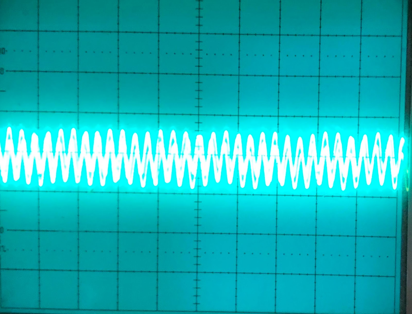
First we use a 100k resistor. We adjust so that our output is half that of the input signal, and by doubling the scale on the oscilloscope we get a overlapping waveform.
Then we add resonance and start self oscillation.
Now we replace the 100k input with a 200k input. To get a similar output amplitude we now have to turn the VCA CV fully right.
Input is attenuated to 50% by doubling input resistor
Unity gain is recovered by turning up VCA CV
But look at what this does to the self oscillation - it is now much higher than the previous one.
Input resistor
I tried hooking the input up to the output from my macbook to process audio. I had to replace the input 100k resistor with a 10k one to get an ok output volume. But processing the input audio was great fun.
Overdrive
I decreased the input resistor and increased the feedback resistor even more to try to overdrive the filter. This did not work very well. I started getting hard clipping and if the input was high enough, something latched up and I had to cycle power.
Later I tried feeding the output back to the input summer instead, using a 20k linear pot as a voltage divider and an inverting opamp (because I have not swapped the inputs on the output OTA, the output is not in phase with the input). This proved so much nicer. I got a controllable overdrive that did a much softer clipping. It did also latch up stuff when the feedback was too high, but a great experiment all in all. I still have to look closely at the signal levels of the original signal to decide a proper range for the overdrive feedback. Oh, and of course the output level gets much higher, this has to be compensated elsewhere. Maybe its possible to tap the signal before the output VCA and do something to decrease the VCA gain CV when the overdrive CV increases. Or this could be done in software.