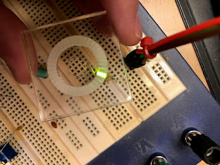
More than three years ago I did a lot of prototyping of LED dials/rings that I will use to indicate the position of the endless potentiometers on my synth.
I can however only find a couple of posts here about it, one is from the early prototyping of a diffuser lense, and the other one from when I sent the PCB to production - but then it ends.
I did however take some photos and videos of everything, so as I just picked up the idea again I thought it would be nice to post about it.
 | ||
| The LED ring PCB, 31 + 1 LEDs in a 270 degree arc (to match a normal potentiometer) |
 |
| Diffuser prototype. Here I've engraved a ring, and then cut slits in an attempt to keep light leakage between elements to a minimum |
 | |
| A similar version, but here the engraving is on a separate piece of acrylic so we have two layers. |
 |
| Not entirely sure about this one, but I think I've engraved both slits and ring, but engraved the slits deeper. |
 |
| Same as above but with the additional second layer. |
 |
| Not sure what combination this is but it's starting to look good |
 |
| My text for this says "cut 3mm outside". I did some versions where i had an additional cut outside or inside to prevent even more light bleeding |
I even did a version where I put tiny black paper dividers between each cell. It worked fairly well but was extremely impractical and would take ages for the number of pots I need.
 |
| I tried cutting a mask in multiple layers of thick paper to prevent light bleeding under the acrylic. |
After all these white diffuser trials, I decided to try out red acrylic instead. That worked wonders!
 |
| This is also a really good version. I think it is a combination of the best cell-and-engraving version with the red lense, possibly with black cutouts |
Here are some videos of the ring in action:
All in all, I was rather satisfied with the result, so I decided to move on to other things.
Then, today, a colleague sent me a link to this video:
https://www.youtube.com/watch?v=tHL4RYGSvg4
Finally, someone has made a good enough commercial version of a led ring:
It is prohibitively expensive though, around $10 per ring!
https://www.aliexpress.com/item/1005005361069637.html
But this got me thinking - how do they actually make those rings? Why does it not bleed between cells, and more importantly - how can I do something similar?
So now I'm back to the idea of cutting a mask again. The Bargraph ring is 3.4mm high, so I will try cutting a 3mm high mask out of black MDF or even acrylic. I am not sure how detailed I can get it so i will try some various versions - from 0.3 to 0.7mm walls between cells, and both engraving and cutting - engraving takes much longer but also uses lower temperatures so it may be possible to get a thinner wall.
 |
| Mask for cutting/engraving 3mm thick material |
I then have a few options. I can try adding a diffuser on top, and then a red layer on top of that, that would probably look quite nice.
Or, I could try placing the mask over the leds and fill the holes with resin, and then sand the top to get either a smooth or diffuse finish. Using a clear resin would give me lightpipes up to the surface, possibly with some internal reflection to even out the light. I could also try translucent resin, or even red resin.
I think this has some chance of looking good, and it would also be fun to try out. I will start out with the laser cutting and see how it works out.


Hmm... that is totally up to taste, I fancy the round LEDs. I think 31 LEDs are too detailed and will need many additional parts to control. I would go for 15+1 or even 7+1 and plan tu use some vanilla IC to control them
ReplyDeleteI agree, it's totally up to taste. Initially I wanted to mimic a continous GUI-ring element, much like a circular progress bar or similar. I tried getting the dividers as thin as possible for this, but the result wasn't good enough for that. As I wrote above, I really liked the discrete led look in the end, so we'll see how it ends up.
DeleteAs for vanilla ICs, it wouldn't be a problem controlling this with any normal shift register, you would just have to add a resistor per diode group - with a constant current sink shift register you get away with a single resistor that sets the current.
I also agree that
I also agree that 31 diodes is overkill. 15 would definitely work very well. The number of additional parts isn't that high though, it roughly doubles. But if keeping cost down was an issue I would absolutely consider. Right now I'm more concerned about the current consumption, but if I use single led indicators that is probably not a big deal.
DeleteDo you have any links to your project btw? It would be very cool to see what you come up with!