The cutoff control is not that interesting, I assume I can tweak the starting point just the same way I did with the two others, and reuse the expo converter from the Juno - after all, the filter core should function the same way, with a doubling in control current resulting in a doubling of frequency.
The resonance on the other hand, is completely different. The juno returns the difference of the filter output and filter input, tapped at the last stage, and returns it to the start of the filter. The jp6 on the other hand, returns the SUM of the output of the first stage and the filter input and returns it to the start of the filter, where it is also mixed with the output of the second stage.
I discovered quite early on that reusing the resonance control from the Juno filter did not work as it should. In fact, I got resonance with a 0V input and the resonance fell when increasing the CV. At last 10V was needed for a 'normal' response without resonance.
I went back to the datasheet, and discovered that the resonance OTAs are actually IR3109s, which means that they have built in exponential converters. This makes a huge difference of course. I went on to duplicate the expo converter from the juno filter, after all it should be a close approximation of the one from the IR3109, and add the rest of the JP6 control circuit. I also re-read the datasheet and it seems the JP6 DAC outputs up to 10.7V (see page 4b, DAC amplitude). Finally, each resonance CV feeds two voices and each voice has two resonance OTAs (In fact, two voices share one IR3109), so I added two additional OTAs to the simulation to get a correct split for the I_abc.
So far so good. But the OTA CV circuit has a trimmer in it. And this trimmer has a huge effect on not only how high the resonance peak gets, but on how little resonance we get too.
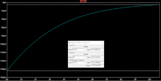
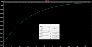
Here are some plots. First of the resonance CV from 0 to 10.7V and the corresponding I_abc current for each OTA. We can clearly see that the lower the CV, the higher the current - and higher I_abc means a higher gain in the OTA. There are three plots, each for a resonance trimmer setting of 0, 0.5 and 1 (wiper position).
 |
| Wiper at 0 |
 |
| Wiper at 0.5 |
 |
| Wiper at 1 |
 |
| Wiper at 0 |
 |
| Wiper at 0.5 |
 |
| Wiper at 1 |
Finally, a plot of trimmer position vs minimum resonance. The top green line is wiper at 0. All lines after the grey one (wiper at 0.5) shows a bump so they are definitely not correct, but are any of the others?
My conclusion then, which I guess is ultimately quite fun, is that I have to understand what is going on. How does this filter create resonance, and what exactly is it that the OTA output defeats. When knowing that, I can go back and calculate what the best output of the OTA is, and get the necessary theoretical gain.
OBTW: Why bother? Why not use the circuit like it is? Well, for one I would not know how to properly calibrate it, and second, I think I still like to keep the resonance control linear and do the expo conversion in software, the way the other filters do.
UPDATE: I tried reading up on Q, resonance etc. It is not easily understood exactly how it comes about. But I DID find some great reasources on state variable filters, that inspired me to try adding more features - tapping bandpass after pole 1 and 3 (6dB) and creating notch / AP versions. Very exciting!
I ended up doing a quite crude comparison of the falloff between the Juno and Jupiter filters. I positioned a marker at resonance frequency and then measured the falloff from the 'plateau' down to it. I found the dropoff to be about 10.3dB and so I have adjusted the Jupiter filter to match this when the resonance CV is 0V by setting the resonance offset trimmer U23 to 0.25.
 |
| Juno filter |
 |
| Jupiter filter |

No comments:
Post a Comment