When I corrected this error though, to my great surprise, lower frequencies got heavily attenuated once resonance went up!
I have checked and rechecked and traced the original JP6 PCB but I always come to the same conclusion - the resistor is there.
I even went back and simulated the filter with and without the resistor, looking at both filter response and phase, and honestly, I can't see ANY difference, except for the attenuation.
 |
| Zero resonance without resistor |
 |
| Zero resonance with resistor |
 |
| Max resonance without resistor, same low frequency gain as no resonance |
 |
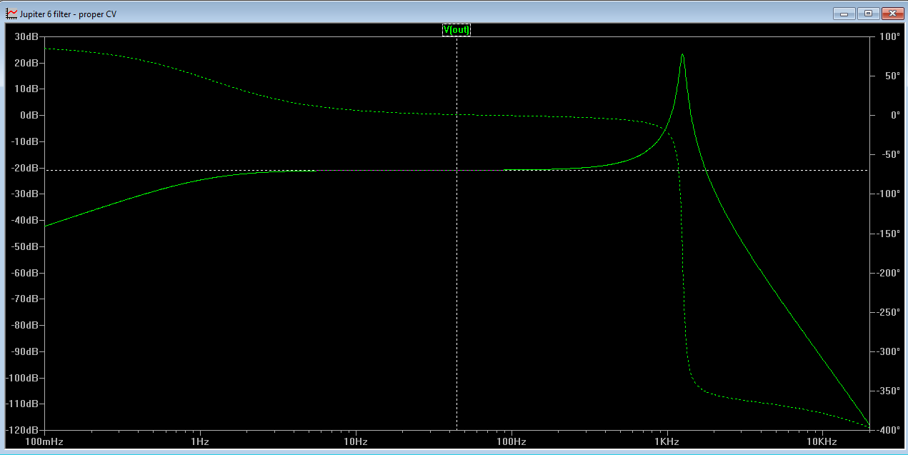
| Max resonance with resistor. gain has fallen by 24dB |
This begs the question: What is the purpose of this resistor/line?
Right now my only two conclusions are either that it is there to attenuate lower frequencies on purpose - exactly the thing other filter designers fight to. Or LTspice simulates the circuit incorrectly.
I guess won't get an answer to the last question until I breadboard the circuit.
Update: Scott Bernardi made a comment about the attenutation here: http://www.bernacomp.com/elec/og2/og3_4pmultimode.html - Without it the resonance would start clipping (depending on the rest of the circuit of course). That makes sense.
No comments:
Post a Comment