Monday, June 29, 2020

A tiny bit of future proofing

I am trying to create a small buffer of parts for my synths, in particular the JP-8. This beast has around 50 BA662 chips in it, each of which costs 50-60 USD to replace.

I stumled upon someone selling pulled 80017A chips from serviced Juno 106's, and bought 18 of them. Status is unknown but they weren't specifically replaced because they failed, more because they WILL fail.

In each 80017A there are two BA662 and one IR3109, both of which go for around 50 USD. I had to pay quite a lot, but if I am able to rescue at the chips from at least TWO of the 18 I will turn a profit (or rather, save money if I ever need the chips).


Saturday, June 20, 2020

Waveshaper current consumption and possible changes

The waveshaper op amps run fairly warm. Thus, I wanted to check the current consumption in case it was off the charts.

On the breadboard, the waveshaper current consumption is:

+15v: 26.5mA
-15v: 27mA
5v: 3.1mA (inc pulse VCA CV)

Of this, the waveshaper part (8 op amps) uses
+15v: 17.7mA
-15v: 18.1mA

Meaning the sub oscillator (10 op amps) uses
+15v: 8.8mA
-15v: 8.9mA

The JLCPCB circuit uses

+15v: 24.7mA
-15v: 24.2mA
5v: 0.5mA

In comparison, the Yusynth VCO (10 op amps + 1 comparator) uses

+15v: 27mA
-15v: 28mA

so I guess the current consumption is not that bad after all.

I am unsure what actually draws the power. I tried swapping 10k and 20k resistors for 100k and 200k around IC1B (pulse output) and the 27k DCO input resistors for 100k ones but that didn't change anything (or actually made it worse).

The sine wave amplitude is too low. Sine amplitude gain is done with a 15k negative feedback resistor and a 1.5k resistor from negative pole to gnd. Gain is 1+15k/1.5k = 11. By replacing the 1.5k resistor we can increase gain.


The VS-1 compared to old and new analogs. Technical details

I just watched an amazing video from Abstract Instruments, the makers of the VS-1: https://www.youtube.com/watch?v=4WwXlRYw_S0&feature=youtu.be.

It compares implementation details of the OB-X, JP8, Prophet 5, Rhodes Chroma and OB-6 and gives tons of useful information. I've tried to summarise it here:

Autotune

Autotune can only do so much for high frequencies, so a good initial trim is essential (for all synths)

JP-4:
Has no autotune, relies solely on the trimmers

OB-X:

  • Measures C5 (around 1kHz), does not adjust scaling, only initial tune offset.
  • Measures each oscillator twice: Once to measure frequency, second to
  • confirm the adjustment. Measures up to six times, if that fails it disables the voice.
  • Autotune takes < 2 sec


DAC:
  • 0 to 5.333V
  • 5.333V / 64 notes = 83.3mV step over 5 octaves, 1V/octave
  • 10 bit but only needs 6 bits to represent 5 octaves
  • In addition: Common VCO frequency CV, 4 octave and 1 octave from left hand control panel for a total of 10 octaves
  • Oscillator bias CV runs through 10M resistor (on a 100k for 1V/oct style summer)


P5 DAC:

  • 7bits, 10.666V reference = 10 octaves, 83.3mV, 1V/octave
  • 7bits fine tune for a total resolution of 14 bits


Rhodes Chroma

  • 12 bit main DAC for CVs, 3 cents resolution (reasonable for the time)
  • 8 bit that sets reference voltage for main DAC, skews tracking, corrects scaling errors in 0.1% intervals
  • Measures the periods at 6 octave intervals for each oscillator [error, should be 6 something else??]
  • Calculates scaling bias (done in 8 bit dac). Also calculates initial tune offset added to main DAC


Prophet 5

  • Rev 1 & 2:
  • Four checks: C3, C4, C5, C6
  • Bias CV resolution is about 1 cent with 128 possible values, about 1 semitone range
  • 7 bit bias CV dac mixed through a 10M resistor (on a 100k for 1V/oct style summer)
  • 40 autotune measurements (4 points x 10 CVs). Takes a long time. ( > 10 secs)
    • Bias CV 1 is used for bottom up to 1/2 oct above C3
    • Bias CV 2 C4 +/- 0.5 octave
    • Bias CV 3 C5 +/- 0.5 octave
    • Bias CV 4 C6 - 0.5 octave and up


Rev 3:

  • 7 checks per osc: C3-C9
  • 14 bits bias CV added as parts of Key CV, resolution is 650uV or 0.8 cents
  • Bias for C0 to C2 is calculated from the others as it takes too long to measure ( > 60 secs)


Jupiter 8

  • 10V output, 3cents/step for 12 bit, < 0.8 cents for 14 bit
  • Measures C3 and C8, uses a formula to calculate a bias CV for each key


Sequential OB-6

  • samples several points and deriving a high resolution correction curve
  • temp sensor, saves temp profiles
  • can recall profiles, does not do any real time calibration per se
  • has "slop" settings to introduce variation


Analog voices

OB-6:

  • No trimmers, everything is done through CV
  • Sub osc on VCO1
  • Can mix waveforms using 2164 VCA
  • Taps all poles of HP/BP/LP filter, mixable using 2164
  • 2164 for resonance control
  • 2164 for panning
  • Splits after voice mix to dry and fx which is mixed afterwards

VS-1:

  • 2164 panners
  • Bi-timbral
  • 4 input analog chorus
  • Analog polyphonic glide

Digital control


  • OB-X: 2.5MHz MCU
  • OB-6: 32bit PIC at 200MHz
  • VS-1: 32bit ARM at 600MHz


Reading/updating CV:

Loop times:

  • OB-X: 14-19ms
  • P5: 9-11ms
  • JP8: 3-6ms


OB-X

  • Pots are scanned using a DAC and a comparator (successive approximation)
  • 10bit CVs, 10 iterations per pot
  • 1-6ms to scan pots (19 on OB-X)
  • Scans pots then updates CVs, thus updating CVs less frequently when loop time is long
  • More complex sample and hold circuit for pitch CV (check, possibly just shifting voltages?). Low leakage polystyrene caps for pitch CV assures stability between updates.


OB-6

  • 12bit ADC over SPI to scan pots and external CV input, pitch and mod wheels. Scanned 256 times per second.
  • Updates CVs at 24kHz - must be fast to update software LFOs and envelopes fast enough
  • 24kHz gives sub 1-ms attack times for 0 to 5v envelopes (looks like 2.5v to me in oscilloscope pics)
  • Smooth LFO rates up to 500Hz
  • Looking at the oscilloscope screenshots, a full attack takes around 0.4ms-0.5ms (each grid line is 0.2ms), at approx 5 samples per 0.2ms (= 24kHz), giving 10-13 samples for attack.
  • Uses pair of 8ch 16 bit dacs for 120 CVs
  • Uses independent CVs per voice instead of common CVs, to be able to add offset biases on a per voices basis, it has NO trimmers!
  • 4051 multiplexers for sample & hold
  • S&H caps on mainboard, S&H opamps on voice cards
  • Separate microcontroller for CV updating, tables in memory for calibration
  • Core logic runs at 1.2V
  • Samples VCO and filter waveforms using 24bit ADCs, AKM 24bit stereo codecs


VS-1

  • CVs updated at 48kHz
  • Single 8 ch DAC
  • 85 CVs
  • Single ADC to scan the endless pots, scan rate is 1kHz

Tuesday, June 16, 2020

Waveshaper bug

I finally got around to testing the waveshaper boards last week. Most of it work flawlessly though I get some clicking when doing large frequency jumps for some of the waveforms. Also, saw and sine waves are not as loud as the others at the same amplitude (which is to be expected I guess, I just need to consider if its ok).

For some reason though, two of the TL074 op amps got really hot and the sub oscillator didn't work. After some probing I found that the -2.5v source output 13.5v instead. I had my wife solder a second board but the same happened there.

I couldn't figure out what was going on, but it suddenly dawned on me when I tried to fall asleep yesterday - I have mixed up the op amp inputs when trying to make a voltage buffer :(

The fix is very easy in CAD, but on the boards I have to cut two lines and solder a new wire:

Cutting the input, it goes to the negative terminal of the op amp instead of the positive. I've also scraped away the solder mask to be able to add a new wire to the positive terminal instead. I will see if I can find a wire tiny enough to fit in the via (which is 0.3mm...). I also have to add a solder blob between the negative terminal and the output.

Cutting the feedback loop between the positive terminal and output. It should of course have been between the negative input and the output.


The board is smaller than it appears btw, here is my finger for reference.
UPDATE:
My wife managed to solder this just fine, after that the filter works flawlessly! The tiny diagonal wire is a single copper strand from a networking cable!


Tuesday, June 9, 2020

DCO v1.3 tested, v1.4 ordered

I'm done testing the DCO that I got from JLCPCB. It worked flawlessly - after fixing a few firmware bugs that is.

I had to change the function of Data Ready to SPI Chip Select, that fixed some startup problems when the DCO had started before the main MCU powered up. Amplitude tuning works incredibly well and sync hard-syncs like it should.

I did however realise a few things:

The current setup with a 56k charge-voltage-to-current converter resistor and a 1nF integrator cap means we cannot reach 20kHz with an amplitude 0-10V. Also, the MCU draws a lot of current, around 150mA it seems. The current firmware allows 8Hz to 8kHz approx.

In addition, the circuit has both an MCU and a DAC, so if we could tap the DAC directly we could make a wavetable oscillator of sorts.

For version 1.4 I did a lot of improvements:

- Exposing the DAC output and changing the buffer resistors from 47k to 22k. The DAC can only drive 60k load, so by reducing the load for the internal buffer we can hopefully connect a second, external buffer that can be used as a digital audio output.

- I've also exposed the buffered dac output. The cap is already exposed in both ends. This makes it possible to connect a resistor in parallell with the charge resistor, to increase the current to the cap.

- All DAC SPI pins have been exposed

- Three utility pins on the MCU has been exposed, to make debugging easier (connecting leds etc)

- To reduce current consumption, it should also be possible to run the device at 3.3v, and reducing the crystal frequency from 32MHz to 16MHz. This requires a rewrite of the DCO firmware, but nothing too complicated.


I've ordered 40 of these from JLCPCB, fingers crossed :-D

Monday, May 25, 2020

Little Phatty overload is just soft clipping

From the time I studied the Little Phatty to build my moog filter, I have wondered if the LP does pre-filter distortion of the signal or if it uses feedback for its overload.

From the Little Phatty schematics it is clear that overload is just soft clipping, and the circuit is extremely similar to what I did for my distortion with in-feedback-loop OTA :-D


The LP:

There are a couple of differences: The moog circuit uses both inputs of the OTAs, and also the same CV (though inverted) for both increasing the amount of distortion and reducing (?) the output gain. A nice trick to keep output at the same level I assume.

The overload CV also controls gain/attenuation of the filter output it seems.

UPDATE: I missed something - in addition to the soft clipping, the output from the distortion is fed back to the audio mixer, thus the distortion also has feedback.

TIL: The little phatty has an analog signal path from pots to synth circuts

I read a reddit thread this morning about a guy that is doing a synth controller front panel. He had the novel idea of switching between using the pots directly to feed an analog voltage to the synth circuit (filter cutoff cv etc) and using voltages from a DAC to do the same. By simultaneously reading the voltage from the pot for patch storage, it would then be possible to load a patch and have a dac generate the required voltage to control the synth, but switch to direct-from-pot cv when the user turns the pot to prevent stepping.

The original poster was immediately beaten down by the knowitalls of Reddit, saying that this was overly complicated and that noone would do it like this.

He countered by claiming that he had looked at the circuit board of a Moog synth and seen analog multiplexers close to each pot, and rationalised that these did what he was thinking about. He also claimed that a video told him that this was the way Moog did it.

Another poster then proceeded to post the schematics for the Slim Phatty, explaining how it was clear to see that the circuits were indeed digitally controlled.

I had a closer look at the schematics and discovered that the original poster was indeed right (though possibly not about exactly how it was done) and the one posting the schematics wrong - the Slim Phatty (and by extension Little Phatty) DO actually have the ability to switch between direct control and digital control. Have a look at this:


The filter pot. Its value is buffered by an opamp (U29), which is then both tapped directly (FILTER_CV) and sent to an ADC through AINO.2 for digital processing/storage.

Digital control: CV from the DAC is buffered by a sample and hold circuit and output as FILT_CUTOFF_BUF

A switch then selects between the CV tapped directly from the pot (FILTER_CV) and the digitally controlled voltage (FILT_CUTOFF_BUF). Notice how FILTER_CV is sent to multiple outputs, depending on what mode is currently selected for the pot.

The selected voltage is sent to the board connector as FILT_CUTOFF...

...and received on the voice bort as FILT_CUTOFF (pin 33)

There, it is mixed with CVs from other sources (modulation etc) into the filter cutoff CV FILT_CONTROL

Finally, FILT CONTROL controls the cutoff frequency of the ladder filter. Thus there is a completely analog signal path from pot to filter.

When I went back to post my findings on Reddit, the original poster had already done so. He pointed out that this is called RAC (tm) in the Slim Phatty manual - "Real Analog Control".

The discussion went on to saying that this must be a marketing trick more than having real value, and funnily enough saying that it had do be something only the phattys use because "the memorymoog and prophet 5 does not do it". I call bullshit on this.It may be true that it is only found on the phattys, but comparing it to 25 years older synths is no way of proving it...

Sunday, May 24, 2020

Noise tested


I tested the first board tonight, the triple noise. Two external parts are needed, a 2N3904 with the collector unconnected, the base connected to GND and the emitter connected to IN, and a 50k trimpot for adjusting the gain of the input.

It works perfectly. Rainy white, oceany pink and deep, rumbling red noise. Mmmm... I breadboarded this back in 2017 and had a lot of fun playing around with it with my then 3 year old daugter. "Daddy, can we go listen to the rain?"


Both orders from JLCPCB has arrived!

Finally, after waiting for over two months, the second order from JLCPCB arrived yesterday. I now have loads of circuits to test:

- JP6-style SVF
- Juno-style OTA filter
- Moog-style ladder filter (but this requires some soldering)
- 4ch mixer
- 4 way VCA
- Three types of CV/sample and hold
- Noise
- VCO, CEM3340 w/waveshaper
- DCO
- Waveshaper
- Led ring

The quality is overall very good, though I have found at least one solder bridge and and one of the led rings appear to have been slightly reworked (oh, and I've already broken a led, but that was my own mistake).

Some pics:


4ch mixer and VCA, with room for v2164 or similar

Top: Waveshaper. Bottom: Ring modulator and 4ch CV buffer


VCO, DCO, two versions of S&H for CV buffering, DAC.


Thursday, May 7, 2020

LED dial light pipes, second try

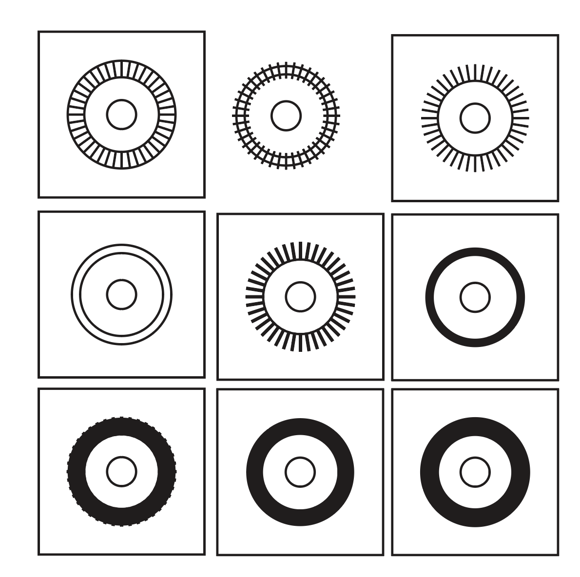
I did some more testing yesterday. I moved the connection points for the slits to the inside of the circle, tried engraving to make room for the leds, tried engraving slits to make them not go all the way through and made a black circle for the center.

Unfortunately I fucked up bigtime when cutting so everything is covered in oily brown residue. But I can still test the concepts.

Initial conclusion: Engraving room for the leds does not work at all. The diffuser has to be some distance from the LED, having it on top of it made the result very blurry. It may be a combination of this and light leakage between the cells, but it seems we get the best result when we have completely separate (cut) cells 'projecting' onto a diffuser.

The previous version with connection points on the outside and a simple diffuser still works the best. It may be that 3mm light pipes (i.e. 3mm plexi) is better to focus the beams.

There is also a lot of light leakage between the cells in the unengraved 2mm version. Not sure if this is because of the short light pipes or the moval of connections from outside to inside. Mostly the edges of the slits light up for at least the two neighbouring cells.

As for trying to make the cells bleed a little to get a continous bar, I feel that that did not work very well at all, the edges get blurry very quickly so I probably have to accept that they are slightly separated.

Using clear 3mm pipes with a 0.3mm spacing to the diffuser gives a continous bar but with slight bleeding. May be acceptable if we want a bar. No spacing will give an extremely sharp edge which is also very cool.

Further testing
- Is engraved room for led combined with cut cells working?
  a: somewhat but not very well

- Are engraved slits working or significantly worse?
  a: not conclusive but may achieve the same with a spacer

- what works best, connection points inside or outside the circle
  a: outside seem slightly better.

- will dividers between the cells improve bleeding
  a: Definitively, but needs to be dark color

- should we cut dividers even closer to minimise contact points?
- Is 2mm (or close to 1mm really) worse than 3mm for light pipes

- diffuser - should it be a continous ring or start and stop at the ends of the led ring?
- diffuser - try individual cells? Does it look cluttered?

I think that the diffuser may be less visible if it is a full circle and not divided into cells, especially once it is red.


Wednesday, April 29, 2020

LED dial light pipes

For the XM8 UI I want led dials around the potentiometers/encoders. I've sent a prototype of the led ring itself to production, and now I had a little time to quickly test some ideas for making it look as nice as possible.

If possible, I want to have a continous ring clockwise from the left to where the current setting is. It may draw too much current, but for now that's my goal. I also want the end of the ring to be as sharp as possible - and in the event of having to use a single led at the time, having as little leaking light from the current led to the ones next to it. Finally, I want the light to be as uniform as possible.

To get distinct sections along the ring, I'm trying out light pipes, one for every LED. They need to have as smooth as possible sides to reflect the light and keep it contained within the pipe, and they must be separated to prevent leakage.

As I'm not sure about exactly how to do this, I made several prototypes:

For the two first ones each light pipe is actually a separate piece of plastic. I thought that painting the sides of the pieces and glueing them back together could be an option.

Number three is a variation where all the parts are still held together at the edge. The gap between them is whatever the laser leaves behind when cutting the acrylic.

Row two: The first one is just to have somewhere to glue the pieces from the center one in row one, as I could not be bothered making the cut lines shorter.

For the center one, I've made the slits between the segments a little wider, my theory was that this would reduce leakage.

As for the four last ones, they test the second design goal - uniform light. Wherever there is black on the drawing there will be engraved white on the acrylic, effectively making a diffuser. There are two diffusers where I have not cut any lines, they will be used on top of the light pipe, and two where the segments themselves were diffused.


I quickly realised that painting and glueing the parts together is not a viable option. The parts are too small and there are too many of them.

The ones with laser-thin slits actually have quite wide slits as it is, so there was no need to widen them.

As for diffusers: Putting the diffuser on the segment means that the slits are still visible. Not a great look.

I also wondered if the diffusing layer should be on top or bottom. It definitely needs to go on top, as the light has to spread before it hits the diffuser.

To test the combinations I taped off a normal led so that it is as narrow as one segment. I put the diffuser layer with the diffuser down against the layer with the segments. The diffuser is clearly visible, the slits are mostly hidden. I would like the diffuser to be less visible, but I think that using red acrylic may help a lot here. Each layer in my test is 3mm btw, so this builds 6mm in addition to the height of the leds.

LED with tape on it to make it more narrow
Segment layer
Diffuser
LED below one of the light pipes.  
There is almost no light leakage between the light pipes, I am really satisfied with this result. There will definitely be visible lines between each segment though, so I may have to experiment with engraving instead of cutting the slits, to allow a little bleeding at the top. An air gap between the layers may also help.


Notice thast the gaps are slightly visible. I think this will improve slightly once the pot is put in a case as there will be no light coming from behind.

With a randomly chosen cap on top. I think this looks great! This diffuser is 4mm wide, I also have one that is 2mm, making each segment almost square. I will test both to see which one I like the most. I will also put black acrylic in the centre of the ring (on the segment layer), and the diffuser layer will be cut so that only the ring protrudes through the front panel.

Thursday, April 9, 2020

Distortion breadboarded

I've breadboarded two versions of the distortion circuit, both with input attenuation and output amplification to keep a 10Vpp signal almost untouched.

Pre-distortion amplification


First I did the version with pre-distortion amplification. With distortion CV at 0V the distortion circuit sees around 30mVpp. This is heavily amplified to distort.

At the other end, a second OTA amplifies the signal. The output has unity gain for a 10Vpp input when CV is around 2.5V.


Hard clipping circuit with pre and post distortion VCAs

Hard clipping, distortion CV from 0 to 5V


Soft clipping circuit with pre and post distortion VCAs

Soft clipping, distortion CV from 0 to 5V


This circuit worked pretty much as in the simulation. I do have some issues with CV feedthrough so centering is not perfect when distortion changes.

I think I have to bite the bullet this time and introduce AC coupling to get rid of this. Placing a cap in series with the 1k resistor to the distortion op amps negative pole seems to do the trick, and will function as a high pass filter as well (beware though, if not chosen correctly low frequencies will not be distorted, in fact they will be attenutated.

Distortion CV at 0V

Distortion CV at 2.5V, almost full distortion and more than double amplitude

Distortion CV at 5V, full distortion. Signal is clipped unevenly by the op amp.

Distortion CV at 2.5V, almost full distortion


Distortion CV at 5V. Very similar to half distortion.

It seems that the real life circuit sees a higher maximum input gain than the simulation. Full distortion is reached much earlier. Also, compared to the OTA in feedback loop version below, the CV response seems exponential, not linear.

OTA and parallel resistor in feedback loop


Then I tried breadboarding the OTA-in-feedback version. I had lots of trouble and could not get it working as expected at all. After much experimentation I ended up with a well functioning circuit. I then started documenting the changes, and realised what was going on: I had inadvertently put a 33k resistor in the feedback of the distortion op amp. This works in tandem with the signal fed back through the OTA, so it completely changes the amount fed back.

As a bonus, the CV control of this version seems to feel much more linear - in the other version all changes came at the start of the CV and very little later. Also, the soft clipping amplitude seems to stay very close to 5V, so in some ways it feels more "correct", the volume doesn't increase as much.

After discovering my error I simulated this circuit too and it works as on the breadboard.

PS: The distortion CV now works in reverse: 0V is max distortion, 5V is no distortion. Unity gain through the circuit is the same as above, approximately 2.5V.

OTA and 33k resistor in feedback of op amp

Soft clipping

Hard clipping, starts very soon after turning the distortion pot.


OTA in feedback loop without the 33k resistor


Now I went back to the circuit that I was TRYING to breadboard and looked at the simulation again. I think I got lost because I couldn't get it working the way I wanted to. Looking at my previous Distortion post, I realised that the hard clipping starts much later, and so the output has a higher amplitude when clipped than in my happy accident.

I then changed parts back to my original design and did some tweaking, resulting in this circuit:


OTA and no resistor in feedback. Soft clipping version


OTA and no resistor in feedback. Hard clipping version
Soft clipping

Hard clipping

Results on the breadboard for versions with OTA in feedback loop


The circuit on the breadboard have some small differences from the simulated one. The output amp uses a 120k resistor instead of a 150k to get unity gain at 2.5V CV. I left the 180pF (Low pass filter) in place, and used 1k pots instead of the resistors to ground on the OTA inputs (except for the distortion OTA in the version without resistor in the feedback.

The potentiometer settings used were:
VCA pot: 620 ohm to ground on negative input, 365 ohm to ground on positive input
Distortion pot: 479 ohm to ground on negative input,  512 ohm to ground on positive input in distortion OTA. For the version without a feedback resistor I breadboarded it as in the schematics.


All oscilloscope pictures are of a 473Hz 10Vpp input wave. Vertical resolution is 5V/square. Output VCA CV is at 2.5V which according to the simulations should give us unity gain for undistorted signals.

First, the circuit with both an OTA and a 33k resistor in the feedback, soft clipping:


Triangle wave, soft clipping selected and distortion CV is at max (5V) meaning least amount of distortion. Output is equal to input
Same as above but with distortion CV at 0V, meaning max distortion. Amplitude only changes slightly but output is heavily distorted.


Hard clipping:

Same as above, but this time with hard clipping. 5V distortion CV, No signs of clipping and still unity gain.

Again same as above, hard clipping, but with 0V distortion CV/max distortion. Heavy clipping and just slightly higher amplitude.

Without 33k resistor in feedback

Now for the circuit without the 33k resistor in the feedback loop. This didn't work very well, the clipping became very asymmetrical. This may be due to the high attenuation of the input signal? I tried replacing the resistors at the positive and negative OTA terminals with a 1k resistor but that didn't change things. Maybe an HP filter capacitor would help?

Soft clipping:

Soft clipping, max distortion CV. The signal passes unclipped but with the output VCA CV at 2.5V the amplitude is only around 7Vpp, and also not symmetrical around 0V.

Soft clipping, no distortion CV. Heavy but unsymmetrical clipping. Amplitude is almost the same as for the previous circuit.
Hard clipping:

Hard clipping, max distortion CV. Same as soft clipping, no surprises there.

Hard clipping, no distortion CV/max clipping, looks very similar to hard clipping for the other circuit except that the clipping is unsymmetrical.


Pre and post OTA breadboarded


510 ohm resistors instead of trimmer for version with 33k in feeback

I tried replacing the 1k trimmer pot on the distortion feedback OTA with two 510 ohm resistors to ground. That gave the following result:


The input is now distorted, meaning the OTA sees a too high voltage.

By measuring the position of the trimmer potentiometer for the distortion feedback OTA when signal does not clip at 10Vpp input (750 ohm), and using the resistor divider equation, I found that the distortion OTA sees +/-165mV. Going the other way, a resistor divider with 15k and 510 ohm will yield the same result. Here I have done the change:


When tweaking the potentiometer I could see that clipping starts right after I started turning the potentiometer. Since there may be production differences, an even smaller input resistor would give a litte room for trimming the input digitally. Here is the effect of 12k, a slightly smaller amplitude:


I also tried replacing the trimmer in the VCA OTA part, that heavily offset the output. It could be possible to use AC coupling here, but we would still get uneven clipping in the VCA at high gain, so it might be best to use a trimmer.

I also did see a slight distortion at minimum distortion CV, but this is probably not related to clipping.

510 ohm resistors in the simulation

In simulations though, it does not work very well:

Signal is much smaller than in the breadboarded circuit when no distortion CV is applied.


I am not sure I will do any more work on this now, I have a well functioning circuit that I will test with some "real" signals instead later (the one with the extra 33k resistor in the feedback, 12k on the input and 120k on the output).