Showing posts with label potentiometers. Show all posts

Wednesday, September 24, 2025

Cleaning up the UI

I'm about to make a prototype of the UI, and have been cleaning up the grid a bit. This is what it looks like right now:


Inspired by the Matrixbrute, I started adding boxes around the related parts. The spacings are way off, but it should give some idea as to how things are grouped:


I do have some problems with this though. The vertical slits don't line up, in fact, they make the whole thing look a bit messy. 

I did also make a ready-for-lasercutting mode, that adjusts all line thicknesses and changes pot and button sizes to fit the shafts, ready for prototyping. Here is the left panel again:


 Now, to see if I could do any better, and after looking at the Waldorf Quantum, I came up with the following (crude) version


 It follows a slightly more logical structure, with the sources top left, then the mixer and post-mixer effects. It also groups the LFO and Arp in two separate two-row areas which gives a nice balance. There is not quite enough room for everything, especially the Arp controls, and I've decided to remove the bit crusher level pot as it isn't particularly useful. I do like this quite a bit. 

Then I decided to color the current version too, and to my surprise, I think it looks cleaner than it did with the "real" colors:

I think I can make both versions work. I will prototype the finished version now, and perhaps I'll have time to revisit the second version in the future.

As for the right side - it also needs a bit of cleanup, there is no room for the frame here, and I guess I should redo the filter to work better visually on the 8 row grid if I choose to go with the modified left side. 


I also think I'll probably ditch the post-filter bit crusher as that can be done by a general DSP, and maybe I'll make a smaller group of pots and no screen (or small oled screens?) for the DSP part. I have even been thinking about doing per-voice FX, or at least chorus, though that would mean not using the FX send lines. We'll see.

Monday, September 22, 2025

Pot and button boards tested

I finally got around to testing the potentiometer and button breakout boards yesterday. They seem to work just fine.

Button board with integrated pullups and diodes on top, potentiometer board (six pots per 10p connector) on bottom

breakout board for buttons, making it easier to connect 8 dupont connector buttons to a single 10 connector

While the buttons worked straight away, the pots gave me a bit of a headache. First time around, nothing worked. Turns out, the connection between the potentiometer and the 10p IDC connector is not particularly good. Pushing on the pot made it work, but releasing it made it lose connecton again.

After comparing with the unmounted connectors I have in my drawer, I realised there are two types. One of them has the sprung contacts further out into the hole:


Top: Connectors from the drawer, the contact fills half the hole

Bottom: Connector that failed. The spring fills less of the hole - also, it looks like the edges of the pot legs, being slightly to wide, have dug themselves grooves at the side of the connector, meaning they may not be able to touch the contacts.

Pot inserted into the working connector

Pot inserted into the non-working connector. When pushing the pot down, the legs are pushed up slightly inside the connector, making contact.

pot inserted into the non working connector (slightly more rounded than the working one).


Thursday, January 9, 2025

Modulation matrix thoughts

I have a working modulation matrix on my XM8 prototype. But something is missing and I haven't had the time to put my finger on exactly what.

Here is a more thorough walkthrough of what could/should be supported.

1) A destination may be modulated by multiple sources, each with their own amount/weight. The sources are summed (to give for example vibrato by modulating a pitch CV by an LFO and summing it with the original pitch)


2) A source may modulate any number of destinations. Again, for example, the LFO may modulate multiple oscillators at the same time etc.


Now, these are dead given. But then we have a more complex one

3) A source may modulate the amount of another source. For example, a separate potentiometer may modulate the amount of LFO applied to the VCO pitch.


Then we have a special case

4) Multiple destinations may control a function, which in turn is the source of another modulation. For example, multiple pots may control an envelope. The output of the envelope may modulate the output VCA.


Strictly speaking, we could also let the destination directly act as a source, leading to

5) Any destination may be treated as the source of another modulation


6) Any destination may be treated as the amout of another modulation


Right here it feels like we're entering FM territory...


Summed up into some general rules:

  • A modulation path consists of a source, an amount multiplier and a destination.
  • A source may modulate a destination or the amount of another source
  • A source may modulate multiple destinations or amounts 
  • A destination may be modulated by multiple sources. The sources are summed after being multiplied by individual amounts
  • Multiple destinations may act together to control a function (LFO, envelope)
  • Pots, destinations and function outputs may all act as sources

It would be a good idea to hardwire most pots to specific destinations

Most amount coefficients in the matrix will be zero. It may be better to have a list of 'active' modulations to reduce the number of coefficientds, but that depends on the MCU and what optimizations it may do on the data.

I think my major mental breakthrough here is that I realized that sources, especially pots, must be able to control the amount.

Things I still wonder about

  • Will it always be correct to add, not multiply, the various modulation paths?
  • For simplicity, should we really allow any destination to act as a source?

Oh, and here are some resources for Teensy math:
- https://forum.pjrc.com/index.php?threads/linear-algebra-library-for-teensy-4-1-robotics-project.69778/
- https://github.com/PaulStoffregen/Audio/blob/master/utility/dspinst.h
 

PS: Multiplying and summing two vectors (or matrices) is called a dotproduct.

Sunday, January 5, 2025

Potentiometer scanner utility board

As I prepare to make a function mockup of the front panel, I've designed a utility board that can scan up to 48 potentiometers. The boards can be chained, allowing for a total of 288 potentiometers on six output pins.

The only input from the mcu is clock, reset, +V and GND.


Shown here: two input muxes (left), one per 10p connector. Only six of the eight inputs are used but all are adressed as the clock is sequential. The board has 8 input muxes in total. On the right is a single mux that selects one of the 8 input muxes for output to the MCU. Everything is clocked by a CD4520 six bit binary counter. Before scanning starts, clock is reset to make sure it is at 0. It can also be reset early if some of the input ports are not used.

Testing shows that a single channel can be scanned at 50kSamples/second, the limitation is the speed of the ADC on the microcontroller. The analog output of the on board mux'es stabilize after approximately 2uS. 

I've tested the circuit on a Teensy 4.0, and as it uses a single ADC for multiple channels, scanning six channels takes around 113uS. This means that we can do 185 samples/second per potentiometer when using all channels.

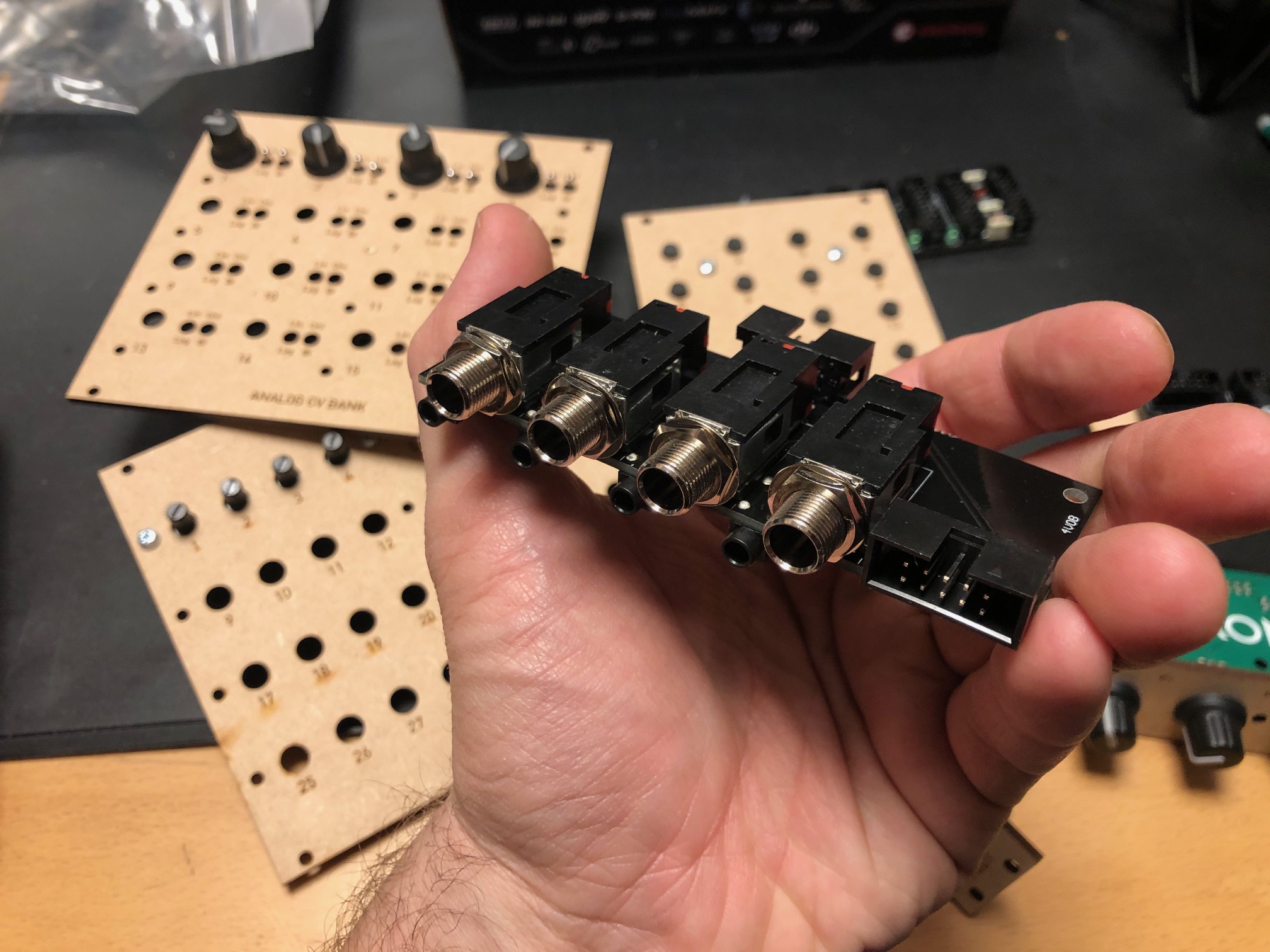
As I'm allergic to soldering, I have been looking for a way to connect the pots without solder. My best and simplest solution this far is to insert the potmeter directly into a 10p IDC connector. It stays fairly firmly in place, with the outer potentiometer pins at pin 1/2 and pin 9/10, and the center pin at pin 5/6. 


If I connect +V to pin 1/2 and GND to pin 9/10, I can connect the pots at either the front or rear row of the connector, reading the value from pin 5/6. 


Front row

Rear row

If I modify the cable a bit, crossing pin 3/4 to center and then 7/8 to center, I can connect six potentiometers to a single 10p ribbon cable!

Crossing two and two wires allows me to connect six potentiometers to one ribbon cable


Friday, December 4, 2020

Tons of new circuits ready!

So much has happened this summer and fall, and I haven't written about half of it! Some of it is directly related to the XM8, but most is utility circuits. I simply decided that I had to take time to do do some intermediate steps before building the final voice cards.

A shortlist of circuits I've designed, breadboarded, tested and finally produced at JLCPCB/DirtyPCBs follows below. Everything has been soldered by my good friend and colleague Stig-Rune!

Analog CV bank with 16 CVs in groups of 4.


For each CV you can select between lin or log/antilog  response, as well as uni or bipolar operation. Per group of four you can select the CV range, 0 to 2.5V, 5V or 10V (or +/-2.5V etc for bipolar). I did fuck up the PCB slightly so I had to cut a trace in three places and solder a wire. Also, I messed up a cable so I shorted the outputs, almost overheating the opamps. After that it worked perfectly. Output is via 10 minijacks and a 10p IDC connector for easy connection to a breadboard.


Quad input/output module with 1/4" jacks


For each module you can select input or output connected to the 1/4" jack, and the opposite will be connected to a minijack. Both ends are also connected to a 10p IDC connector for easy connection to a breadboard. For each channel there is an option of 10 or 2 x attenuation and 10 or 2 x gain, meaning you can either have a unity gain circuit, a 5x attenuation (for line out-ish) or 5x gain (for input).


24/48 button module, digital

A digitally scanned button module (without the microcontroller), chainable for up to 48 buttons. Serially read so it only requires four pins + power, making it possible to combine it with the potentiometer module on the same cable.


8 to 64 potentiometers module, digital


A digitally scanned potentiometer module (without the microcontroller). Each module has 8 potentiometers, and 8 modules may be chained for a total of 64 potentiometers. As with the button board, it only requires four pins, and it shares the same clock and reset pins at the button module so a total of six pins + power is needed for all digital modules. During testing I discovered that pin 9 on IC2 - one of the address lines - should have been connected to GND. Now it is floating, so it isn't possible to set the address correctly. It's an easy fix however.


4 x IDC Passthrough module

A simple panel with IDC connectors on both sides, makes it possible to route IDC connectors as a group through the front or back panel without putting the cable through a hole.


Bitcrusher

A combined 12 bit sample rate reducer and bit rate reducer with analog and digital control, based on a PIC16F18446 microcontroller with built-in ADC. Described in separate posts. I've ordered 25 of these.


20kHz LPF

A filter module that can be used as an anti-aliasing filter for ADC input and reconstruction filter for DAC outputs. I use the same configuration in the Bitcrusher and intend to use this for the combined DCO/wavetable oscillators. The circuit comes from this page: https://www.analogfilters.com/anti-aliasing-filter/


Voltage Controlled Distortion

A distortion module for the XM8, the second of the two pre-filter FX (the bitcrusher being the other). Controllable distortion amount and output amplitude, as well as switch between hard and soft distortion. Untested.


Memory


A DIL mounted SMD chip, 128Mbit, for use as sample memory for the wavetable oscillators etc. Untested.


Prophet VS keyboard controller

A new revision of the 68b01 clone for the Prophet VS. I've ordered 20 of these so I have for future sales. They have all been programmed but are missing legs.


Modular synth power bus board

16p Doepfer standard boards with 7 connectors. A bit short but cheap to build.


10p and 16p breadboard IDC connectors

Tiny boards with an IDC connector on one side and legs on the other, making it easy to use ribbon cables between breadboards and modules


Unbuilt designs

In addition, I have PCBs for the following that has NOT been soldered yet:


Breadboard power and I/O module

Has input for +/-15v and a regulator for 5V. Also has IDC connectors for chaining multiple boards, and small chain-boards that can be fitted upside down to connect multiple boards. Connects to the power busses on the breadboard. No more risk of messing up polarities! Also: a 10p Doepfer compatible power connector, although the doepfer uses +/-12V, not 15V, and a 10p I/O connector that connects a ribbon cable to 10 pin headers for easy and stable connections. Pin 10 may be connected to ground with a jumper.


Breadboard coax connector and I/O module

A board with four coax connectors and the same 10p I/O connector as the board above. Will give stable connection points for oscilloscop, function generator and other gear that uses coax.


15-to-12v DC converter module

A module that converts +/-15v from either a molex connector or a 10p IDC connector to +/-12v and +5v. Output is through a 16p connector, compatible with the Doepfer standard. Also has a two pin header for injection of Gate and CV 


All in all 16 different boards! Needless to say, I'm more than pleased! I'm getting so close to being able to test an initial voice board, I just need to program some digital envelopes.


Bonus

I finally got the following soldered and ready for testing:

Two versions of the sample and hold buffer, one with some large caps and some filtering and one in a tiny DIL14 format, both quad sample & hold:


Then the second version of the DCO, this time with DAC output to make it a wavetable oscillator too:


Monday, May 25, 2020

TIL: The little phatty has an analog signal path from pots to synth circuts

I read a reddit thread this morning about a guy that is doing a synth controller front panel. He had the novel idea of switching between using the pots directly to feed an analog voltage to the synth circuit (filter cutoff cv etc) and using voltages from a DAC to do the same. By simultaneously reading the voltage from the pot for patch storage, it would then be possible to load a patch and have a dac generate the required voltage to control the synth, but switch to direct-from-pot cv when the user turns the pot to prevent stepping.

The original poster was immediately beaten down by the knowitalls of Reddit, saying that this was overly complicated and that noone would do it like this.

He countered by claiming that he had looked at the circuit board of a Moog synth and seen analog multiplexers close to each pot, and rationalised that these did what he was thinking about. He also claimed that a video told him that this was the way Moog did it.

Another poster then proceeded to post the schematics for the Slim Phatty, explaining how it was clear to see that the circuits were indeed digitally controlled.

I had a closer look at the schematics and discovered that the original poster was indeed right (though possibly not about exactly how it was done) and the one posting the schematics wrong - the Slim Phatty (and by extension Little Phatty) DO actually have the ability to switch between direct control and digital control. Have a look at this:


The filter pot. Its value is buffered by an opamp (U29), which is then both tapped directly (FILTER_CV) and sent to an ADC through AINO.2 for digital processing/storage.

Digital control: CV from the DAC is buffered by a sample and hold circuit and output as FILT_CUTOFF_BUF

A switch then selects between the CV tapped directly from the pot (FILTER_CV) and the digitally controlled voltage (FILT_CUTOFF_BUF). Notice how FILTER_CV is sent to multiple outputs, depending on what mode is currently selected for the pot.

The selected voltage is sent to the board connector as FILT_CUTOFF...

...and received on the voice bort as FILT_CUTOFF (pin 33)

There, it is mixed with CVs from other sources (modulation etc) into the filter cutoff CV FILT_CONTROL

Finally, FILT CONTROL controls the cutoff frequency of the ladder filter. Thus there is a completely analog signal path from pot to filter.

When I went back to post my findings on Reddit, the original poster had already done so. He pointed out that this is called RAC (tm) in the Slim Phatty manual - "Real Analog Control".

The discussion went on to saying that this must be a marketing trick more than having real value, and funnily enough saying that it had do be something only the phattys use because "the memorymoog and prophet 5 does not do it". I call bullshit on this.It may be true that it is only found on the phattys, but comparing it to 25 years older synths is no way of proving it...