Showing posts with label antialiasing. Show all posts

Friday, December 4, 2020

Tons of new circuits ready!

So much has happened this summer and fall, and I haven't written about half of it! Some of it is directly related to the XM8, but most is utility circuits. I simply decided that I had to take time to do do some intermediate steps before building the final voice cards.

A shortlist of circuits I've designed, breadboarded, tested and finally produced at JLCPCB/DirtyPCBs follows below. Everything has been soldered by my good friend and colleague Stig-Rune!

Analog CV bank with 16 CVs in groups of 4.


For each CV you can select between lin or log/antilog  response, as well as uni or bipolar operation. Per group of four you can select the CV range, 0 to 2.5V, 5V or 10V (or +/-2.5V etc for bipolar). I did fuck up the PCB slightly so I had to cut a trace in three places and solder a wire. Also, I messed up a cable so I shorted the outputs, almost overheating the opamps. After that it worked perfectly. Output is via 10 minijacks and a 10p IDC connector for easy connection to a breadboard.


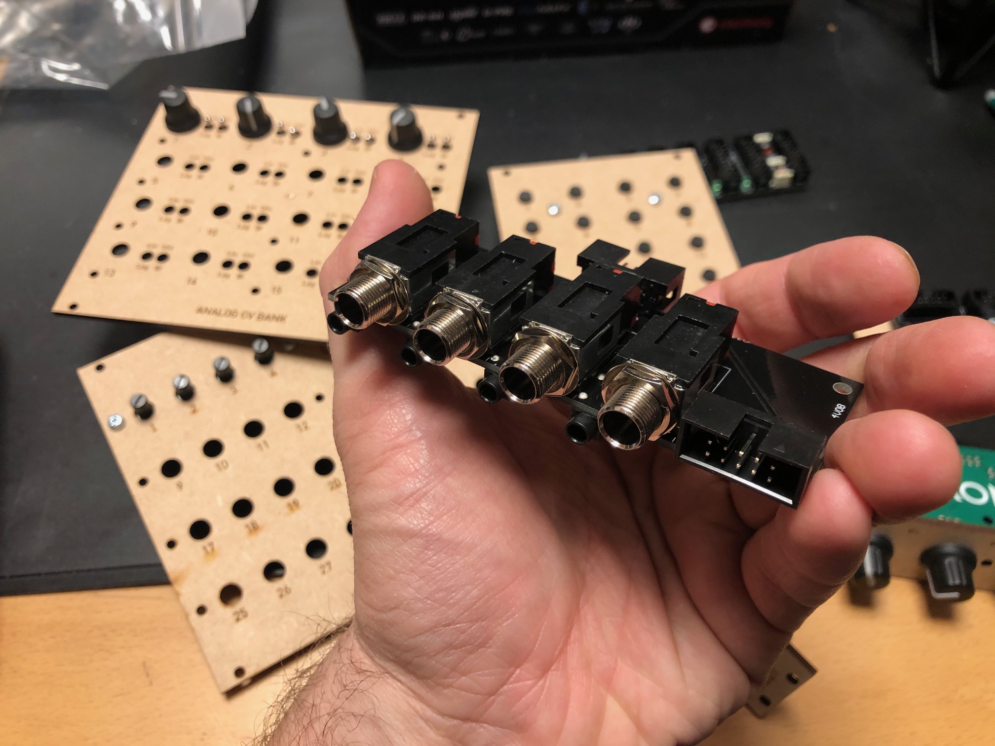
Quad input/output module with 1/4" jacks


For each module you can select input or output connected to the 1/4" jack, and the opposite will be connected to a minijack. Both ends are also connected to a 10p IDC connector for easy connection to a breadboard. For each channel there is an option of 10 or 2 x attenuation and 10 or 2 x gain, meaning you can either have a unity gain circuit, a 5x attenuation (for line out-ish) or 5x gain (for input).


24/48 button module, digital

A digitally scanned button module (without the microcontroller), chainable for up to 48 buttons. Serially read so it only requires four pins + power, making it possible to combine it with the potentiometer module on the same cable.


8 to 64 potentiometers module, digital


A digitally scanned potentiometer module (without the microcontroller). Each module has 8 potentiometers, and 8 modules may be chained for a total of 64 potentiometers. As with the button board, it only requires four pins, and it shares the same clock and reset pins at the button module so a total of six pins + power is needed for all digital modules. During testing I discovered that pin 9 on IC2 - one of the address lines - should have been connected to GND. Now it is floating, so it isn't possible to set the address correctly. It's an easy fix however.


4 x IDC Passthrough module

A simple panel with IDC connectors on both sides, makes it possible to route IDC connectors as a group through the front or back panel without putting the cable through a hole.


Bitcrusher

A combined 12 bit sample rate reducer and bit rate reducer with analog and digital control, based on a PIC16F18446 microcontroller with built-in ADC. Described in separate posts. I've ordered 25 of these.


20kHz LPF

A filter module that can be used as an anti-aliasing filter for ADC input and reconstruction filter for DAC outputs. I use the same configuration in the Bitcrusher and intend to use this for the combined DCO/wavetable oscillators. The circuit comes from this page: https://www.analogfilters.com/anti-aliasing-filter/


Voltage Controlled Distortion

A distortion module for the XM8, the second of the two pre-filter FX (the bitcrusher being the other). Controllable distortion amount and output amplitude, as well as switch between hard and soft distortion. Untested.


Memory


A DIL mounted SMD chip, 128Mbit, for use as sample memory for the wavetable oscillators etc. Untested.


Prophet VS keyboard controller

A new revision of the 68b01 clone for the Prophet VS. I've ordered 20 of these so I have for future sales. They have all been programmed but are missing legs.


Modular synth power bus board

16p Doepfer standard boards with 7 connectors. A bit short but cheap to build.


10p and 16p breadboard IDC connectors

Tiny boards with an IDC connector on one side and legs on the other, making it easy to use ribbon cables between breadboards and modules


Unbuilt designs

In addition, I have PCBs for the following that has NOT been soldered yet:


Breadboard power and I/O module

Has input for +/-15v and a regulator for 5V. Also has IDC connectors for chaining multiple boards, and small chain-boards that can be fitted upside down to connect multiple boards. Connects to the power busses on the breadboard. No more risk of messing up polarities! Also: a 10p Doepfer compatible power connector, although the doepfer uses +/-12V, not 15V, and a 10p I/O connector that connects a ribbon cable to 10 pin headers for easy and stable connections. Pin 10 may be connected to ground with a jumper.


Breadboard coax connector and I/O module

A board with four coax connectors and the same 10p I/O connector as the board above. Will give stable connection points for oscilloscop, function generator and other gear that uses coax.


15-to-12v DC converter module

A module that converts +/-15v from either a molex connector or a 10p IDC connector to +/-12v and +5v. Output is through a 16p connector, compatible with the Doepfer standard. Also has a two pin header for injection of Gate and CV 


All in all 16 different boards! Needless to say, I'm more than pleased! I'm getting so close to being able to test an initial voice board, I just need to program some digital envelopes.


Bonus

I finally got the following soldered and ready for testing:

Two versions of the sample and hold buffer, one with some large caps and some filtering and one in a tiny DIL14 format, both quad sample & hold:


Then the second version of the DCO, this time with DAC output to make it a wavetable oscillator too:


Tuesday, October 6, 2020

Nyquist and reconstruction filters in practice!

I assume you've heard about the Nyquist sampling theorem? It basically says that you have to sample a signal at twice the sample rate of the highest frequency you want to represent, that's why CDs have a sample rate of 44kHz - to be able to reproduce signals around 20kHz.

You may even have heard that doing so, you are not only able to reproduce an approximation of the original signal - you can reproduce an exact copy.

But have you actually seen this happen in practice? Let me show you! 


Sampling

A/D and D/A conversion is fairly simple in its basic form. Use an ADC and check the signal amplitude/level at set intervals. DAC is the reverse, set the amplitude of the output to whatever you got from the ADC (There is more to it than that for high quality signal reproduction, but for the sake of the discussion, and for the level of accuracy I need this suffices). 

Try this at home, looking at the output on an Oscilloscope and you'll quickly realise that the output looks nothing like the input. It has jagged edges, you can clearly see the height and length of the individual samples as output from the DAC. 

This is because there is one (two) more very important element(s) needed. To prevent aliasing - a higher frequency signal (outside of the audible frequency range) masquerading as a lower frequency one, we need to use a low pass filter before the ADC to remove frequencies that cannot properly be captured, e.g. frequencies above 1/2 of the sampling frequency.

When playing back the signal we need to do the same - as the DAC outputs a stepped signal it will generate lots of higher frequencies as well. By using a filter with the same cutoff - this time called a reconstruction filter - those are removed (once again, this is more complicated in practice for a high quality signal, but let's forget about that for a minute).


Ok, so that all sounds great on paper. Output a stepped signal and apply some magic, and you should get the original signal. But it can't be that easy, right?


Let's look at some photos:


DAC output (top) vs output after reconstruction filter

Here we see the output of a sampled sine wave (top) vs the output after the 20kHz reconstruction filter. It looks amazing! It works for other waveshapes as well of course, though if we were to zoom in on the edges of the triangle wave we would see that it's slightly rounded - this is because the frequencies required to reproduce it faithfully have been removed by the two filters. This is of course not a big deal as we wouldn't hear them anyway. 

Sampled and reconstructed triangle wave, tips are rounded by filtering.


The effect is even more pronounced with square waves which get a clear oscillation at the edges


Increasing the frequency of the input shows that the DAC output no longer resembles the input as closely - it has very few samples per cycle of the sine wave:


Now things start getting strange. Increasing the frequency even further "distorts" the DAC output even more. Remember, Nyquist says that it should be possible to reproduce a sine wave with only TWO samples per cycle. It sounds incredibly strange, but it actually works! Here is a 15kHz signal, filtered at 20kHz. The DAC output looks nothing like the sine wave it is supposed to represent:


Seeing this for the first time blew my mind. How is it even possible?! Well, read up on the theory behind it in Steven W. Smiths awesome book "The Scientist and Engineer's Guide to Digital Signal Processing" (available for free as separate pdfs from his web page) if you want the theory.


Effects of filtering


Now, there are some effects of filtering still present. First, we get some phase distortion, which increases as we approach the cutoff frequency of the filters. Looking at the input and output sines we can see that they don't line up properly:


As far as I know, this is not audible on its own. It WILL however be audible if the signal is mixed back with the original signal (which incidentally is how phasers are made). (PS: The photo is slightly misleading. Some of the apparent phase shift is only a delay between the input and output due to the time it takes for the DSP chain to process the signal. But the phase shift definitely increases as we approach the filter cutoff)

The second effect is that the amplitude (volume) of the output will decrease as we approach the filter cutoff. This is nothing special to this circuit, it's just how filters work - they do not have an absolute cutoff point, instead they gradually attenuate more and more. Having higher order filters with more stages will help - I'm using six poles in mine. High quality reconstruction filters however, do this differently. As we know how the filter affects the amplitude, we can do the reverse in advance - increase the volume of those frequencies. This cancels out the effect of the filter, keeping the volume constant for much longer. I have not bothered with this in my circuit as we're talking about fairly high frequencies anyway.