Showing posts with label DIY. Show all posts

Sunday, January 8, 2017

The ETI Vocoder

I can't remember if I've posted about this earlier, but for quite some time now I've planned on building the ETI Vocoder. I was approached by a guy who wanted me to help him etch the circuit boards, and we spent at least a year planning for this, touching up the original drawings and adding/moving connectors etc.

In the end though, after buying presensitized PCBs and doing a few test etchings, I decided not to do this at home anyway. I simply have too few time slots long enough to do the setup, etching and cleanup.

What I ended up doing instead was redoing the boards and send them off to be professionally produced. I have shrunk all the boards as much as possible (while still using through hole components). I've split the internal excitation board into two separate pcbs so that all pots are soldered to a board.


In addition, I've combined the LP/BP/HP versions of the voice board into a single circuit. This means that you have to add some solder bridges and that some parts are left out for some of the boards, so populating them is slightly harder. However, it also means that I was able to make dual channel boards that, when repeated 7 times, turns into the full voice board. Using a service like dirtyPCBs, 7 similar smaller cards are much cheaper than one large one.


In retrospect I've realized that I could possibly simplify the circuits a bit, since the left channel on a card will never be HP and the right never LP (or the other way around, I can't remember).

I've also managed to jam all the non voice boards (except one of the internal excitation parts) into two 10 x 10 cm pcbs, keeping the cost really low.


Sunday, September 6, 2015

Pogo pins

Spring loaded pins, also known as pogo pins, spring loaded test pins etc, are a neat tool to keep pins pressed against a test point or interconnect point. I intend to use five of them for In Circuit Programming, removing the need for permanent ICP pins in my circuits.

While searching the web for such pins I realized brand name ones are insanely expensive. Ebay to the rescue! As often is, china products are available to fulfill your needs. I found that the most common ones are named P75-something. But what does this something after P75 mean?

I found this image, showing all variants. I went for the P75-B1 which has a very sharp tip perfect for holes in the PCB.

Friday, April 24, 2015

Practice makes perfekt. Or not. But close

As I decided to use PIC32MX chips for the voice cards, I had to learn how to solder tiny TQFP packs with 0.5mm leg spacing. I've been worried about this for some time, and to try to learn it without breaking anything important, I ordered up some QFP-to-through-hole adapters and the cheapest chips I could find. 

Yesterday I tried soldering them for the first time.The first chip was a complete disaster. I used way too much solder lead. I tried removing it with some solder wick but that was no success.

After watching a video on drag soldering, things started to go a bit better, and on the third chip, a 100 leg QFP, it got very good (except for a bent first leg).

My method ended up being this:

- Apply a tiny amount of solder on the lower left leg (on the PCB of course).

- Position the chip using SMD pliers. Once the chip is in the right spot, tack down the lower left leg with the soldering iron (in my left hand, even though I am right handed) while still holding the chip with my right hand.

- Adjust the chip if necessary (NB: Only do adjustments while the solder is still liquid, reheat if necessary.

- When all legs are in the right position, solder the upper right leg. The chip will now stay in place.

- Now apply a generous amount of liquid flux to all legs. This is very important for a good result.

- On each side, melt a tiny amout of solder onto the two first legs, in effect creating a solder bridge. Then drag the soldering iron across the legs several times. The solder will spread nicely. I use a huge chisel shaped tip, using the corner of it works very well. If you get a solder bridge, move the iron from the legs and outwards and it will disappear (if you haven't used too much solder).

I had to wear a pair of magnifying glasses to be able to do this properly. It is actually really hard to see if you get any solder between the legs and the PCB at all. To be sure, I had my wife bring them to her lab (she's a PhD student working on hormones and using fish cells for her work, so she has some really powerful microscopes in her lab) and take some close up photos of the result

Here are the photos. In my experience, 10 x magnification would be great for soldering while 20 x is perfect for studying the result in detail.

My second and third attempts. 

I managed to bend the first leg while tacking down the chip, so this will never work. The rest look good though

The mishap at maximum magnification

I am rather pleased with the result, especially since this is the first time I've tried to do it.

My wife's kick-ass stereo microscope. I want one but they sell for $4000+ used... There are cheaper models out there though.


Saturday, February 28, 2015

Power and DAC

It's been a busy week. I've designed prototype cards for an AD5557 based DAC card (parallel input dual output) and a separate multiplexed 2-input 32-output sample and hold card, and sent both off to OSHPark for production.

Today I designed two PSU cards based on Ken Stone's CSG66 module - one dual voltage (+/- 15V) and one single voltage (2.2-9.6V) that I'll use as the analog and digital PSU in future projects.

Sunday, February 1, 2015

Working OMM prototype

I've spent the days since getting back to Norway making an OMM prototype running on an 8 bit PIC18F458 @ 20MHz.

Things are looking very good indeed, except for speed of course. I've implemented:

- node structs
- function pointers and pointer lookup
- matrix array calculation
- DAC output to 14 bit SPI DAC (MAX544
- input buffer reading and outputbuffer writing

In addition I've coded the following node functions:
- Sum
- Invert
- Invert each side (positive stays positive etc)
- Ramp (but without proper interval calculation)
- Delay line (allows loops in network)
- Input
- Output

Next up should be
- Timers for constant output to DAC
- SPI input for controllers (but that is not possible without a second SPI module)
- JSON parsing
- Table lookup for tuning and exponentialization.

Here is the first output from the OMM - the frequency is too low to get a good image on the scope:


A few specifics on the SPI and the DAC:


The DAC accepts a maximum SPI speed of 10MHz. In the tests I did, I ran the SPI at F_osc/4, which means 5MHz when the oscillator frequency is 20MHz. I achieved what I think is a sample rate of about 89kHz but that is without any calculations between samples. In practice then, it seems the maximum DAC rate is slightly less than 180kHz when running the SPI clock at 10MHz (from the PIC that is, it is entirely possible that you can achieve higher speeds otherwise).

Here is  the code for the DAC tryout:

void writeToDac(){
unsigned int dacout;
/**** DAC ****/
SPI1_Init();
TRISC = 0; //trisc as output
LATC.B0 = 1;
dacout=0;
// The following code runs at about 89kHz.
while(1){
LATC.B0 = 0; //must write directly to latch (didn't work with PORTC.B0!)
SPI1_write(hi(dacout));
SPI1_write(lo(dacout) & 0b11111100);
LATC.B0 = 1; //latches values in DAC.
dacout += 2048;
}
}

The first time I got the DAC working it looked like this:


The visible steps are because I chose to use only 32 steps to speed things up and to see what is happening. After removing all delays and maximizing the speed it looks like this:


Here is the SPI clock btw:


Tuesday, January 20, 2015

On voltages and other practicalities

While dreaming up the OMM I have for some reason constantly kept thinking about the output from the DACs as 5V, with a OMM value of 0 corresponding to 0V and 65536 to 5V while at the same time intending to use a 1V/octave VCOs and having the pitch CV controlled from the OMM.

This, of course, leads to a severe limitation: the synth would not be able to span more than 5 octaves, and no tuning or modulation would be possible for the highest and lowest notes.

There are a few different solutions to this problem:

1) one could use a separate output as octave selector. By keeping this at 2.5V normally, we could add or subtract 2 octaves and still have 0.5V left for tuning and modulation. This will however lead to having to do some tricks when receiving notes outsidere the normal 5 octaves.

2) one can use 10V instead of 5V for the DACs. This gives us the same 10 octaves as adding an octave selector CV. However, this requires a redesign of some modules such as the VCA.

3) one can change the input resistor on the VCOs so their response is 1/2V per octave, again giving us the same 10 octaves.

I am not sure which one to choose. I will have a closer look at how other midi-2-CV converters do this.

I also need to figure out how many octaves to support. If it should be possible to do one-octave pitch bends 10 volts only allows 8 full octaves, and even then other modulations and tuning must be kept separate.

LFOs and modulation


Our numerical LFOs will have an amplitude from 0 to 64k. But when using the LFO to modulate the pitch CV, to get a vibrato effect, we want it to increase the pitch for half the cycle and lower it for the other half. In essence, we would be better off using a signed int. In other cases, and for other operators, we are only interested in the positive parts of the waveform. And in any case the DACs would normally only output a single-polarity signal (though this can be fixed).

Again, I need to check how others are doing this.

Other things to think about when it comes to LFOs is that it should be possible to adjust their starting point and direction (up/down), as well as to choose whether or not to reset the cycle at the start of a note and to sync it to an external clock.

Multiplication vs attenuation/scaling - virtual VCAs


I've realized that we need an additional function, one that treats the inputs like they are between 0 and 1 when multiplying them. This is analogous to how a VCA works, when the CV is at max, the output is the same as the input. When the CV is half of its Max, the output is attentatet by 50% etc. In other words, the output is scaled depending on the CV, between 0 and 1 times the input.

Monday, January 19, 2015

Ramp generation

If the running time of the matrix calculations is constant and triggered by a timer, generating a ramp is simply the task of adding the same number to an accumulator variable every cycle.

But since the number added is never exactly the number necessary for a correct ramp progression (we are dealing with integers after all), we will accumulate an error. This may be ok, but we should keep control of how big the error may become and take actions to prevent it from becoming too big.

If we work with 16 bit numbers, we will get an error of maximum 1/65536 per cycle. But assuming we are running at 44.1kHz, this will accumulate to an error of 44100/65535 = 67% in one second! Not very accurate I'd say.

Lets do the cslculation the opposite way. If we decide that yhe maximum acceptable error is 1% per second, what resolution do we need for our interval?

Well, in one second, we should be at most 0.01 * 65536 = 655 away from the correct answer.  At 44.1kHz, this means that the maximum error per cycle must be less than 655/44100 = 0.015, or 1/67th of the error we get from using an integer.

To remedy this, we may store the accumulator and the value to add as a number with more bits (in doing this, we will multiply the interval, or rather, calculate it differently) and divide the accumulator down to 16 bits when the output is needed.

To get the necessary precision we need to be able to store 1/67ths. By adding 6 bits to the number we can store 1/64 fractions, which is not quite 1/64 but may be good enough, or we can add an additional two bits and get a 1/256 precision, making the accumulator and interval variables 24bit (it may be practical to make them 32bit while at it, not sure).

Converting the accumulator back to 16bit is simply a matter of shifting it 8bits to the right.

Looping or multi stage ramps (envelopes)


When the ramp reaches the desired height, we want to stop adding to it, reset it or even start subtracting from it. This means that every time we have added something to the accumulator, we should check its value and possibly perform an action. We may even have to keep track of state, as what stage of an envelope we are in. The state, as well as the accumulator and value to add should be stored within the ramp node's struct if we want a truly node-type agnostic algorithm that lets us have any number of any type of node (unlike the Matrix 12 which has a fixed number of ramps, LFOs etc).

Sunday, January 11, 2015

Exponential VCA with temperature correction

As promised in the previous post, here is a new take on the exponential VCA. This time the CV input has been modified and a tempco resistor added. This is the same scheme used in many VCOs for the pitch CV.

As the 1k 3300ppm tempco resistor is the most used tempco resistor in DIY designs, possibly making it easier to get hold of, I have decided to use it for this design as well. This, however, means that the input CV has to be amplified before it is attenuated by the resistor voltage divider formed by R21 and TR1.

There are two ways to build this circuit - trimmable and not trimmable. For the not-trimmable version, use the exact values found in the diagram - 57k (47k + 10k) on the CVTRIM input and 23k (22k + 1k) in the feedback loop. All resistors should be 1% or better metal film resistors.

For a trimmable version you may replace the CVTRIM input resistors with a 10k resistor. The input voltage should be around -2.6V, and you may connect a 20k or 25k potmeter between 0 and -15V to achieve this. This potmeter will subtract a voltage from the input CV, which affects the maximum and minimum amplification possible. Both move in the same direction, if the maximum drops, the minimum will also get lower.

You may also change R11 to a 18k resistor and R19 to a 10k potentiometer. This pot will affect the "distance" between the maximum and minimum amplification. Turning the potmeter to the right and increasing the resistance of R19 will make the maximum amplification drop, but at the same time the minimum gets higher (i.e. you will not be able to attenuate the signal as much).

CV (linear) and response (Exponential) without trimming. No tempco used but temperature is 24 degrees celcius. Trim voltage is -15V, not 15V as it says in the picture.


The maths behind this

The maximum input to the transistor base when no correction CV is added should be -0.2072V. Using the R21/TR1 resistor voltage divider means that the output from the IC1A opamp must be -11.8V.

This voltage should be reached when the CV is 5V, which means that the CV has to be amplified -11.8V/5V = -2.362 times.

We will almost achieve this if we select a 23k feedback resistor and a 10k input resistor.

To reach -70dB, the correction CV must be 0.106V at the transistor input. This means it has to be 6.042V at the opamp output due to the resistor voltage divider. If we  choose to input -15V at the CVTRIM input, we need an input resistor (R1+R3) = 23k * -15V/6,042V = 57.1k

Or

If we choose a 10k CVTRIM resistor, the input correction CV must be 6.042V * -10k/23k = -2.63V


UPDATE: As pointed out by MB in the comments, there is an error in the schematics. The output from IC1A/B should go to the top of the 56k resistor and the Q1/Q2 transistor bases should be connected to where the 56k meets the 1k tempco, as shown in my original sketch here:


Saturday, January 3, 2015

Exponential VCA, first try

After getting a very good result from the linear VCA, I felt like making an exponential version as well. The Lockbox VCA has an exponential converter, so why not try to use the same thing here?

I have written a long text about the exponential converter and learned a lot about it, so I had everything I needed in terms of theory ready. Reading this will give good insight to why the exponential converter is like it is and how it works, but it is not necessary to follow the reasoning in this post.

The most important result from the document is that the output current from the converter, Ic, can be written as:

   Ic = Is * e^(Vb/Vt)

where

  • Is is a constant reference current
  • Vb is the voltage at the base of a transistor in the converter, which is a fraction of the CV.
  • Vt is a constant that - unfortunately - changes with temperature.


The exponential curve

My big question when I started looking at the exponential VCA was how exactly the exponential curve should be. Where should it start?

Now, this may sound strange, one would always like the control current to be 0A when the CV is 0V, and at its maximum when the CV is at max. Unfortunately, the formula above will NEVER be zero. When the CV is 0V, e^(Vb/Vt) equals 1, and so Ic = Is. We may add a negative voltage so that e^(Vb/Vt) becomes less than one, but it will still never be zero.

The question then is, how close to zero do we have to get before we cannot hear the signal passing through the VCA any more?

Offness

I tried some component values and looked at the result on the scope. It looked good, but when I tried connecting the output to an amplifier, I could easily hear the sound even when the CV was 0V. After some googling, and realising that I had what I needed in my bookshelf, I discovered a few nice rules.

Douglas Self writes about this in the chapter "Volume and Balance control" of his book "Small signal audio design".

He states that a good volume control should cover at least 50dB, and at least -70dB attenuation is needed to get a good "offness", where you cannot hear much of the signal any more. But what the heck does that mean?

I will not go into details about decibels, but here is a rule of thumb: If you increase a signal 10 times, you have raised the volume by 20dB. Increase it a 100 times and you have raised it by 40dB. Similarly, divide the signal 10 times and you have decreased it by -20dB. Divide it by 100 and you have decreased it by -40dB.

Volume controls (and VCAs) work by attenuating the input signal. The input should be at its highest and the volume control only "pinches off" parts of it, reducing the volume. So, as a consequence of the previous paragraph, when the volume is reduced to 1/10th of the initial volume, it has been reduced by -20dB.

To figure out how much -50dB and -70dB are, we can use the formula

   Change in dB = 20 * log(Output/Input)

Where log is the 10-logarithm.

Refactoring the formula gives us that

   Output = Input * 10^(Change in dB / 20)

At -50 dB:

   Output = Input * 10^(-50 / 20) = Input * 0,00316

At -70 dB:

   Output = Input * 10^(-70 / 20) = Input * 0,000316

In other words, the output is 0.00316 times the input when reduced by -50dB and 0.000316 times the input when reduced by -70dB. So, now we got something to aim for.

What attenuation to aim for

So, should you go for the -50dB or -70dB slope? Well, that depends of course. I have build both, and there is a significant difference in the offness. There is a faint but clearly audible sound from the -50dB VCA even when the CV is at 0. With the -70dB VCA I had to walk up to the speaker and put my ear next to it, and even then could only hear an extremely low sound (my wife actually heard it before me).

The problem with the -70dB contra the -50dB is that what you gain in offness, you lose in fine control of the higher-volume parts. You have to turn the volume pot of the -70dB one a bit before you reach the starting point of the -50dB one so you get less pot travel for controlling the rest. The difference is not extreme but it's necessary to be aware of it.

I would probably go for the -70dB, but if you do not need the output to be completely off (maybe the output is masked by the output of other sounds?) you may choose the -50dB version.

-50dB curve. Straight line is CV, 0 to 5V. Curve is response of a 5V input signal. Note: not finely adjusted so top misses 5V a bit.
-70dB curve. Straight line is CV, 0 to 5V. Curve is response of a 5V input signal. Notice how the bend is sharper and starts later than on the -5dB one.

Calculating vital parameters

We already know from the linear VCA that a maximum control current of 1.515mA will give unity gain within the circuit used, so we'll use that as a starting point. I will only show calculations for -70dB, but it is similar for -50dB and -100dB.

With a maximum current of 1.515mA, the minimum current must be

   0.000316 * 1.515mA = 0.479 uA for -70dB attenuation.

To see what this means for input CV voltage, we need to use the exponential formula again.

Remember,

   Ic = Is * e^(Vb/Vt)

which means that

   Vb = Vt * (ln(Ic) - ln(Is))

Vt varies with temperature, it is in fact

   Vt = ((degrees in celcius +273.16)*1.38*10^-23) / (1.6*10^-19)

This means that at 20 degrees celcius ("room temperature"), Vt = 25.3mV

Is is a constant that we choose ourselves. From my initial trials I found that an Is of 15V / 510kOhm = 29.4uA worked fairly well, so I chose that for my further calculations

Now we  can find Vb:

   At 0.479uA, Vb = 25.3 * 10^-3 * (ln(0.479*10-6) - ln(29.4*10^-6)) = -100.6mV

   At 1.515mA, Vb = 25.3 * 10^-3 * (ln(1.515*10-3) - ln(29.4*10^-6)) = 96.27mV

In other words, the voltage span needed to control the VCA from 0 to -70dB is

   96.27mV - (-100.6mV) = 196.8mV

Ah, but our CV spans 5V, and it starts from 0, not -100.6mV? Well, that can easily be corrected by an opamp summer with gain < 1.

By using a 1k feedback resistor and a 25k input resistor, our 5V CV is reduced to a 0.2V CV. To move the starting point to -100mV we only need to add a negative voltage. If we use the negative supply rail, -15V, we have to divide it by 150 to get to -100mV. As it has to run through the same 1k feedback resistor, we need to run it through a 150k resistor to get this attenutation.

A word of confusion

I have neglected to mention one thing. The exponential converter described above requires a positive Vb and it has its positive reference current Is and control current Ic running down into the collectors of the exponential converter transistors.

The output of the opamp summer connected to the CV circuit however, inverts the voltage giving us a negative CV. At the same time, the LM13700 requires a positive current running INTO pin1.

Fortunately, a PNP-transistor based exponential converter works exactly opposite of the NPN based one described in my texts about the exponential converter. Instead of a positive Vb it requires a negative one, and its reference current Is must run out of the collector. So by connecting the reference current generating resistor to -15V instead of 15V we are good to go.

Temperature is a bastard

Although we now have a working exponential VCA, it only responds accurately to the CV when the temperature is exactly 20 degrees celcius. This is because of the Vt mentioned earlier.

To see just how bad this gets, we can do some quick calculations:

TemperatureVtIc maxPercentage of 20 degrees
023.6mV2.02mA133%
1024.4mV1.74mA115%
2025.4mV1.52mA100%
3026.1mV1.33mA88%
4027.0mV1.18mA78%
5027.9mV1.05mA69%

This may pose a bit of a problem. It is likely that the temperature will be higher rather than lower than 20 degrees, so the current will probably never be too high. Still, it may be a good idea to add a trimpot to the voltage that moves the starting point so that you can adjust your VCA to work best at your desired temperature. This will also alter the maximum attenuation, but not dramatically.

An exponential converter that works better with temperature changes will be suggested later.


Suggested resistor values for -50dB, -70dB and -100dB:

attenuationGain, R15CV, R4Trim, R3Trim if variable voltage/pot.
-50dB1k33k292k220k
-70dB1k25k150k120k
-100dB1k18k84k275k

If a trim pot or variable voltage is connected to the CVTRIM input, use the resistor value in the last column. If not, connect CVTRIM to -15V.
Dual exponential VCA with -50dB attenuation, 0-5V CV

The Xonik VCA revisited

I have spent some time tweaking the LM13700 based linear VCA. I read somewhere that one should aim to use the highest possible value for the control current I_abc, which makes sense:

The way the VCA works is

  • The input voltage is divided down to something the LM13700 can handle
  • The voltage is attenuated/amplified by the LM13700, the highest output signal is found when the control current is at its highest.
  • The output current from the LM13700 is converted into a voltage and amplified by the output opamp.


Now, the lower the maximum controlling current is, the higher the output amplification must be. The higher the amplification, the more noise you amplify as well.

With this in mind, I took a closer look at the circuit and the LM13700 datasheet.

The datasheet states that the maximum Iabc the IC can handle is 2mA. Any more than this and the device self destructs.This is why some circuits out there have a 10k resistor connected between the transistor collector and the IC. The Iabc input (pin 1) of the LM13700 will stay close to the negative power rail, and the collector can never move above 0V (more than this and it would turn off as the collector has to be more negative than the emitter, and the emitter is connected to the CV inputs opamp's virtual ground). This gives a maximum voltage across the resistor of 15V, and a current through the resistor and into the LM13700 of 15V/10k = 1.5mA.

This can safely be changed to a 8.2k resistor which will give a maximum current of 1.83mA. It could actually be reduced even further, from my experience the Iabc input never goes much below -14V, but at least this is still on the safe side.

After some experimentation I decided to use a 3k3 resistor on the CV input, R2, when using a 0 to 5V CV. The maximum input current will then be 5V/3.3k = 1.515mA (A higher CV input will make this go higher, but it will be limited by the 8.2k resistor on the LM13700 input so we will never break the LM13700).

With a CV of 5V, I then tried different values for the input and output signal resistors. Assuming we want the input signal to be allowed to swing as much as possible, I added a 15V signal through a potmeter to the input and watched when the LM13700 started clipping. I ended up using a 27k input resistor, R1. To get the output signal back to the same amplitude (The opamp will start clipping with an input signal of about 13V, so I tried this with a 10V signal) I had to use a combination of a 22k and a 1.2k resistor in the feedback of the output amplifier, R15 and R17.

I also tried various other configurations. One may want to use a 0 to 10V CV instead of the 0 to 5V (the CV has to be positive, so if you want to use a -5 to 5V CV you have to bias it into 0 to 10V first. A negative CV will not harm the VCA in any way, it will just be fully turned off when the CV is less than 0V). If you are certain your input signal will never be above 5V or 10V you can also get away with less attenuation/amplification and thus less noise.

Here is a table of good values to use:
CVSignal swingInput resistor R1Output resistor R15 (+R17)CV input resistor R2
0-5V+/-5V5.6k4.7k3.3k
+/-10V12k10k + 560R3.3k
Max27k22k + 560R3.3k
0-10V+/-5V5.6k4.7k + 680R6.8k
+/-10V12k10k + 1k6.8k
Max27k22k + 1.2k6.8k

You can of course use a potentiometer instead of the output resistors, this will let you tweak the output perfectly. My experience however is that this is unnecessary as long as you use 1% resistors and the values above.

Dual VCA circuit using 0-5V CV


Ps: The additional input resistors are changed from two 510R resistors to one combination of 470R + 22R and one 510R. While this adds an additional resistor, it is well worth it in terms of balance / centering. Alternatively use a 1k potentiometer instead, with one side connected to the positive input and the other to the negative input. The center pin should be connected to ground.

Input vs output signal. The topmost wave is the input. The output wave is slightly off center.

Input vs output signal with a different balance - the waves overlap nicely.


PPS: The output buffer inverts the phase of the signal, this can be remedied by adding a second opamp with unity gain.

Disclaimer: The Xonik VCA is mainly inspired by the LM13600 VCA found on the Bergfotron pages and the linear Lockbox VCA 2 found on the Lockbox Synth pages

Wednesday, December 31, 2014

Xonik VCO

I have spent a lot of time lately understanding the exponential converter and temperature correction built into it. I have even written a long document about it that I will publish as soon as I find a place to put the files.

Now, after understanding most of it, I have built a tiny VCO. The core is the well known Terry Michaels core from the electronotes articles, the same as the ASM-1, Ken Stone Catgirl synth and the PicoVCO (which in turn is presumably the same circuit as the Hearn Morley HMVCO1c). The waveshaping is a somewhat modified version of the picoVCO for the triangle part combined with the pulse circuit from the Yusynth VCO. All wave outputs are +/-5V.

The PCB layout is heavily inspired by the PicoVCO v2.0, but I have kept the linear FM input and moved the triangle symmetry potmeter off board so that all pots are on the motherboard. The symmerty circuit is also somewhat changed. Physically it is about 21 x 33 mm and it has 13 pins, so it's slightly larger than the PicoVCO.


Saturday, March 22, 2014

New panels

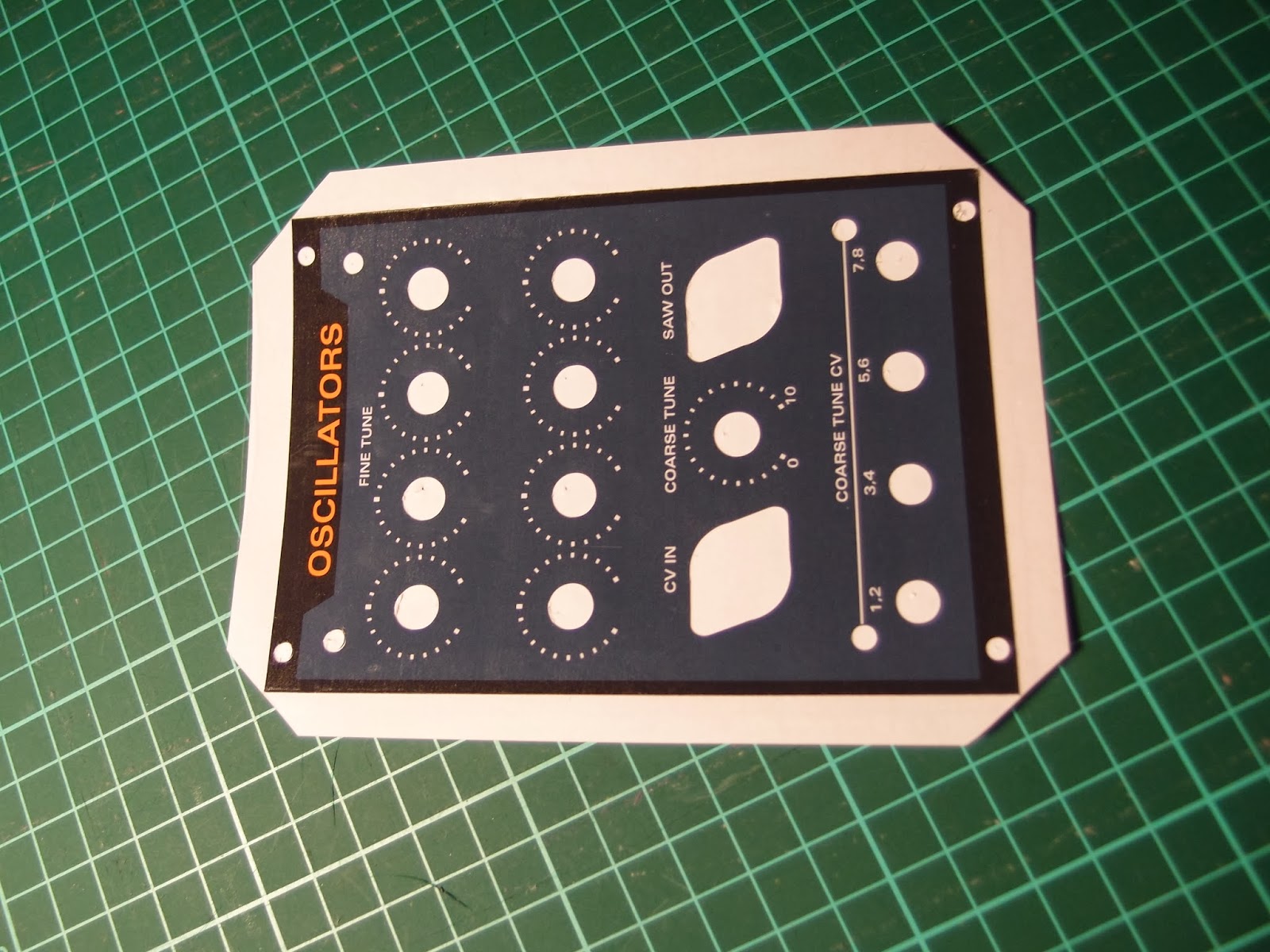
This week I've finished five new panels and prepared prints for three more. I've done two more oscillator panels, two sub oscillators and one 7-saw controller. I've also printed two more sub oscillators and one controller. Since the edges of the first oscillator panel didn't get as sharp as I wanted when folding the plastic around the edges, I've decided to cut the foil along the edges this time.
Plexi glass panels before attaching the adhesive film

Three oscillator modules - the first one to the left has plastic folded around the edges while the new ones are square cut for a sharper edge. I've also realized that I will run out of orange potmeter caps. Unfortunately, Re'an has stopped producing these so it's hard to get more. I've found some similar looking ones on Ebay, they seem to be 1mm wider but it may work out ok.
Finished sum oscillator and 7-saw control panels

Close-up of the sub oscillator. Note the input polarity switch, setting this to the opposite of the input wave will give that cool saw-within-saw wave shown in an earlier post

Tuesday, March 11, 2014

Tiny but crucial bug fix on the suboscillator board

A couple of weeks back I populated the first single suboscillator board, but much to my dismay it didn't work. I didn't have time to inspect it further, but I suspected it was related to the CD4013 flip flop as I had some trouble getting it to work originally. I ordered some more from a different source and they arrived yesterday.

I swapped the old chip for the new one, but it still didn't work. I then rebuilt the first part of the circuit on a breadboard, and it sort-of worked, but both flip flops in the package seemed to flip and flop at the same frequency, which they definitely shouldn't.

Today, I tried adding in a 2k2 resistor between the D and not-Q ports, as well as a 100nF cap from D to ground, a trick I found somewhere online when I originally designed the circuit. This made the circuit work again.

Doing this on the PCB would require me to cut some traces, which would be a lot of trouble, especially on the SMD-based quad suboscillator.

Luckily, when i replaced the 2k2 resistor with a wire, while leaving the cap in place, it still worked :) I soldered two caps onto the pcb as well, and it too worked like it should. I have not tried the board at various frequencies, but for the time being it seems to work fine.

While searching for solutions to my problem, I came across this post named "cd4013 weird shit" - that really sums up my thoughts about this whole problem too...

The fully populated sub oscillator board. It looks a bit like a bug of sorts, don't you think?

A closeup of the 100nF capacitor. Also note the beautiful curved cutouts, I just love the boards OSHPark are able to produce!

Wednesday, January 1, 2014

How to make cheap front panels

Due to our recent car purchase, I expect money to be a bit tighter than usual in the next months. I still need some cool front panels for my upcoming polyphonic/super saw synth. I have therefore been looking for ways to create decent panels at a low price instead of using Schaeffer/front panel express or similar services.

Today I completed the first prototype, a panel for the 8-saw oscillator, and this post explains the process in detail.

I have the luxury of co-owning a Silhouette Cameo cutter with my wife. This machine, while meant for scrapbooking and cutting vinyl for arts & crafts, works perfectly for cutting all sorts of soft materials. While you can get away with just an x-acto knife or similar, the machine makes the job so much easier and the end result much better.

Requirements

For the panels, you need the following:
- 2 mm thick perspex/plexiglass or similar hard plastic glass
- Adhesive-backed glossy photo paper
- Adhesive-backed transparent plastic

I got my perspex from Biltema here in Norway, but you can get similar stuff elsewhere. Make sure it is 2 mm, any more and you may not be able to attach the mini jack sockets, any less and the panel will bend too easily.

The photo paper I used is called Skyhorse Premium Quality Glossy Photo Paper, 130g, self-adhesive cast-coated. I got it off ebay in the UK. It is rather thick, and the ink I use (Canon CLI-55xx) is not absorbed well enough to protect it from wear and tear - it smudges easily even after drying for some time. This is however no problem as long as the paper is covered with the adhesive transparent plastic

The adhesive plastic I use is the kind used as a dust cover on books. It comes in glossy and matte finish, I've chosen the glossy one.

The process

Perspex

First I designed the panel in Illustrator. When doing this, I added cross hairs to all circular components, to tell me where to drill holes. When satisfied with the design, I made a copy of it and removed all but the outline and cross hairs. I then printed this design onto a piece of the adhesive photo paper, trimmed the edges using a paper cutter and attached it to the perspex. To make it easy to remove after drilling, I put the paper on top of the protective film that covered the perspex.

I then drilled all holes using a 1 mm drill bit in a drill press. It's much easier to get an accurately positioned hole using such a small bit first. Remember to also drill holes for any key tabs on the potentiometers.

Some of my holes are very close (1 mm) to the edge of the perspex. I drilled these first, in case they crack the perspex, so that as little work as possible is lost. Be very gentle and do not put a lot of pressure on the drill.

I then drilled 3 mm holes, even in those places where the end hole is supposed to be larger than that - still to get a better accuracy.

Then I used a conical drill bit to drill any holes larger than 10 mm. Finally, I drilled any remaining 6 and 7 mm holes.

After drilling all the holes I used a scroll saw to cut the edges and straightened them by sliding the panel along a metal file. This is the end result:

Cut and drilled perspex
Note that I tried to drill the holes for the potentiometer key tab only partially through the perspex. This was a bad decision as the plastic extrudes slightly, making the hole visible on the front even after attaching the photo paper. Had I drilled it all the way through, it would probably have been invisible.

Photo paper

After creating the raw perspex panel, I printed the panel design onto the adhesive photo paper.

The Silhouette cameo comes with a plugin for Illustrator that lets you add what is called registration marks to your drawing. Later, when you want to cut out parts of the design (holes for pots etc), the Cameo recognizes these registration marks and knows where the design is located on the paper. The plugin costs $40 but is well worth the money.

Panel design with registration marks in the corners
Next up is to cover the panel with the transparent plastic to increase its durability. I decided I wanted the edges to be well protected as well, so I came up with a way that let me put the plastic around the edges and onto the back. If you do not need this, just put plastic all over the panel and cut along the edges of the front panel (after creating holes for the pots etc).

In my case, I had to cut away parts of the photo paper around the edges of the panel so that the plastic film would not stick there. As the photo paper already has a non-stick backing paper, you only need to remove the photo paper itself. However, it is hard to cut through the top layer only, so I did instead cut all the way through:
Cut two grooves about 10 mm apart.
After cutting two grooves, I turned the paper over and put some Scotch magic tape over it to keep it in place. I then did the next side the same way etc:


Finally, I removed the photo paper from the parts I had cut out:


I could now cover the whole paper with plastic film:


 After covering the paper, I attached it to the cutting mat of the Silhouette Cameo:


Based on the same Illustrator design, I created outlines for the potmeter holes etc in the same position as the previously created cross hairs. I made sure to make the holes about 1 mm larger that the holes I drilled, as the silhouette is not accurate enough to get a perfect hit. The design is then sent to the machine and "printed" onto the panel. Due to the thickness of the plastic and paper combined, I had to set the cutting knife to 8, and even this proved to be a bit too little in some cases. Ideally you want to cut all the way through the photo paper but not through the backing paper.


I now carefully removed all the cut out parts using a sharp hook


Then I cut off the edges using a paper cutter. The corners are cut diagonally to be able to wrap them around the edges


Finally, I removed the panel from the backing paper and attached it to the perspex


After attaching the front panel components (knobs, jacks etc), all edges are covered and the result is quite pleasing. The plastic is slipping slightly from the photo paper close to the edges, this will probably not happen if you do not fold the plastic around to the back. Also, when tightening the DIN-jack sockets the plastic bulges slightly, this can possibly be prevented by cutting the plastic closer to the screw holes.


All in all I think the result is very good, especially considering the price and the time it took to create it. 

Sunday, November 24, 2013

Updated saw suboscillator

I have been working a lot on the saw divider circuit lately. Last night i finalized a prototype that works for all audible input frequencies. It can also use both saw waves that start high and ramp down and the ones that start low and ramp up, as inputs.

The circuit has two outputs - saw and square wave, and the saw wave has two modes - frequency division and a more exotic one where the frequency is sort of both doubled and divided. Have a look at the pictures later to see what I'm talking about.


The divider works on the same principle as earlier, by shifting half of the saw teeth up and then reducing the amplitude back to +/-5V. However, it now uses fewer parts than my initial prototype and achieves more. Instead of using an offset voltage to center the wave around zero, it uses a capacitor to do the same thing. I've also added input and output buffers to the flip flop, and the rather complex voltage dividers used for the square wave have been replaced with a resistor ladder and an op amp buffer instead. The need for trimmer pots has been reduced to a single one, and all resistors are from the E12 standard values. The need for a RC-network between D and not Q of the flip flop also disappeared once I introduced the buffers.

The input is connected to a switchable inverting/non-inverting op amp buffer. The comparator used to make the initial square wave needs the input saw wave to ramp down to output the correct square wave necessary to generate a saw wave on the output. If your input wave ramps up instead, flip the buffer polarity switch. Running the "wrong" kind of saw wave through the comparator will lead to an interesting, useful and very nicely sounding output, so feel free to try both polarity settings independently of the input wave.

You may also use other input wave types. The output won't be a saw wave, but will have a frequency related to the input frequency, and be within the same amplitude range. Try it out!

In addition to the saw output, a square wave output with +/-4V amplitude is provided. This will work independently of the type of input wave (well, for "normal" waves anyway) and always have close to a 50/50 duty cycle.

The single 100k trimmer pot (I use a 20 turn one, but any multi turn will do) adjusts the matching of the two saw teeth that are combined to make the new half-frequency wave.

Output

These pictures show the various modes in real life. The scale in all pictures is 1 square vertically = 5V.

Saw wave

First, the saw wave output when the input is not inverted:

Input wave

Output wave, half frequency

Input and output shown at the same time

Inverted saw wave input

Then, the saw output when the input has been inverted (the input itself is the same but the invert switch has been flipped):

Input wave
Output wave - notice how it forms a crude saw wave of half the frequency but with the opposite phase as the input wave and made up of four small saw waves. It sounds great.
Input and output shown at the same time
The reason why we get the strange wave is that the square wave used to lift half of the input saw tops has been shifted 1/4th of a cycle, so instead of lifting a whole saw tooth, it lifts half of one and half of the next one.

Square wave

Finally, the square output. As a square wave is already generated to shift the saw up/down, making a square wave output is only a matter of scaling the amplitude to the correct +/-4V range:


Input wave
Output wave
Input and output shown at the same time