Showing posts with label voice controller. Show all posts

Monday, October 13, 2025

Testing new cards

I'm testing the new cards that arrived this summer - in particular the digital voice card controller

Errors found

VCO: 

- Square wave is probably inverted, just like on the previous version of the waveshaper

- When properly tuned for 1V/oct, the lowest frequency is > 8.1758 which means the VCO cannot be both calibrated to 1V/Oct using trimmers AND reach all MIDI notes. A fix is to add a 1.5MOhm resistor from the summing point (or before the secondary 1V/Oct input jumper) to -12V.

To do

- Tune VCO

- Trim WS 

To test

- VCO frequency vs waveshaper and square wave generator, is the phase inverted?

- Lowest possible frequency for VCO, looks like trimming down won't go as low as DCOs?

- Recon-filter and wave output from digital board, including switching on the analog board

- Control pins on the digital board, though since midi works we know we can control everything. 

What works

- Distortion! :-D 

- Noise

- VCO waves in general

- WS wave mixing is now perfect 

- Midi input on digital card

- DCO tuning

- CV DAC control with 5V and 50MHz signal (3v3 also works but only at 40MHz)

- Rear soldered header on the Teensy 4.0 

- I2C port expanders 

- Winbond W25Q128 flash chip integration from Teensy. Not tested with DCO but uses same circuit. Was tested with W25Q128_test.ino (adapted from https://github.com/msnbrest/W25Q128)

- PCB output /recon filter on digital board. However, output is 0-2V, e.g. not bipolar and not a big enough range.

Thursday, January 20, 2022

Voice card build and testing

I should really start off by screaming as loud as I can: "It's aliiiiiive!". This monday I hooked up a DCO, the waveshaper, a waveshape mixer, the Juno filter and an output VCA, all controlled by the voice controller and its internal modulation matrix. For the first time, I'm able to play my synthesizer using an external midi controller. It feels amazing! To think it took 7 years to get this far...

Anyway, it is not without bugs, but that's why I'm doing it this way in the first place, to test everything and how it works together.

There are a lot of things that work great right from the start. The waveshaper does its job perfectly, giving triangle, bi-directional saw, pulse with PWM and two sub oscillators with selectable square/saw output. 

The waveshape mixer CV generator I designed earlier works perfectly, as does the pulse wave amplitude control. 

The filter filters, though the range may be a bit lacking. It resonates beautifully too. I have yet to calibrate it and test it fully after moving from +/-15v to +/-12V. 

Finally, the output amp and envelope works great, though I had to fix a few rather hard to find bugs in my code.

Now, for each module, here are some things that must be fixed or improved.

Waveshaper

The sine wave amplitude is +/-4V while all the others are 5V. This can be fixed in the voice mixer by changing the input resistor or I can fix it on a new revision of the waveshaper.

The saw and triangle waves have noticeable ringing (noticeable on the scope, not necessarily audible). Adding caps in the feedback of the output will remove most of this. The rest goes away in the filter but I am not sure if it affects anything else. 

Pulse width: I don't think the pulse width is quite narrow enough.

When calibrating the symmetry of the sine wave, I can't seem to get a perfect setting that also gives a centered triangle wave. It is not a big issue though, but it means that the triangle is slightly "lower" than the other waveforms, perhaps by 0.5V or so. It is not audible, but it may affect how the circuit clips when mixing multiple oscillators. I'm going to leave it as it is for the time being.

The square wave sub oscillators are not centred. This is because the reference voltage used in centring is derived from -15V, and when changing this to -12V the reference is wrong. Again not audible but nice to fix.

The triangle and sine waves have a very visible notch at the end of the phase, more about that in the DCO paragraph.

Waveshape mixer

As I wrote in my last post, the AS3364 has a sort of dead band in both ends of the CV. Since all waveshape mixer CVs are generated from one input, it means that there is no way to compensate for this without changing the CV generator. In practice, the dead band means that one waveform fades out completely before the next one has reached its maximum. This is especially apparent in the saw to pulse cross fade, where the wave has become a square before the square has reached its top. It is not particularly pronounced so I don't think I'll do anything about it.

DCO

These are not properly wired up yet, so some of these things may go away - right now they run with the wrong calibration circuit and only produce a 0-5V wave when they should give us 0-10V (at least that's what the waveshaper expects). To compensate for this, I'm running the wave through a non-inverting op amp amplifier with 2x gain.

There are a few shortcomings/bugs in the DCO. First of all, some ringing is introduced along the way. I've added a cap to the feedback of the non inverting amp, a 15pF in parallel with the 56k resistor I'm currently using.

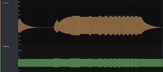
It looks like discharging the DCO cap goes too slowly. Either that, or we are limited by the slew rate of the op amps. In any case, this means that the drop from top to bottom of the saw wave is not instantaneous. When generating the triangle wave we invert half of the saw wave to get the "missing" portion of the triangle - but since the falling edge is not perfectly vertical, we get a notch at the end of the triangle phase. I can't say I hear it, but  at 8kHz it is very visible on the scope.
DCO discharge is not vertical enough, leaving a notch in the saw wave.

Adding a 5p cap across the DCO output op amp takes away much of the ringing at the start of each cycle


15p cap takes away even more of the ringing. Saw output from the waveshaper at the bottom, some new ringing has been reintroduced.

Clicking on envelope retriggers: When we play a new note without releasing the previous one, we get a bit of clicking. So far I've been able to identify two probable causes - output amplitude and centring after the filter, and glitches in the DCO.

The DCO glitches manifest themselves as discontinuities in the triangle wave, it suddenly and abruptly changes value. The reasons are:
  • When changing from a high to a lower pitch: It looks like the period timer is not reset. Instead, the period is reset when the original frequency would have been reset. This means the amplitude is too low and the start/end matching of the triangle fails.
Saw does not reach its maximum as it is reset at the "old" frequency
  • When changing from a low to a higher pitch: now the timer lasts too long, meaning the cap is charged more than it should. It reaches its max and flats out, both distorting the saw/tri and introducing a spike with too high amplitude. That would definitely sound like a click. 


The last of these is to be expected. The DCO is supposed to check the amplitude against a known voltage, but without calibration this won't work. The other one on the other hand, is stranger. I need to check the code.

I also got a more serious error while testing the very limits of the DCO. When playing OCT+4 on the MPK-25, switching between e and g makes the DCO drop to a much lower frequency for a single cycle before recovering. It happens consistently. No idea what makes it happen.


Finally, the range of the DCO is currently too narrow. It maxes out at around 8.5kHz but should reach at least the double or ideally above 20kHz. Replacing the integrator cap and regenerating the timer code will probably solve this.

Filter

As with the DCO, the filter cutoff range needs looking into. I have not tried calibrating the filter at all, so it may not be a real problem though, but it looks like the filter is not open enough with CV at 5v.

There is also something going on when changing the wave frequency. Obviously, when the wave frequency reaches the cutoff point, higher frequencies will be attenuated more, so with the filter at a fixed cutoff, switching between two notes will make the amplitude jump up and down. This may be part of the click-sound I'm hearing. Also, the filter has some form of DC filtering, so the balance/centring of the wave changes with waveform/content. This is particularly visible with narrow pulse waves and resonance. Again, a bit of calibration may improve this but I also need to see what other synths do. Also, introducing keyboard tracking means that relative amplitude should not change as much between the notes.

Some kind of noise at the start of the envelope (not visible in the CV). This was before I hooked up a probe to the filter output so I don't know where it originated from


Weird glitch in output, again, no idea what this was, especially since it is not at the start of the envelope.

Quick retriggering that changes frequency leads to amplitude changes after filter

Output from filter is not centred. Had a lot of resonance and wave was not symmetric around the X axis.


Envelopes

These are software, and mostly finished. I still need to hook them up to the GUI to make it easier to test them, but for now they are controlled through 7bit midi. As they have a very large range - 1ms to 30s, I have to use some kind of linear-to-exponential mapping, or we would not get any resolution at the lower parts of the range. 

I feel that the mapping I use now still does not have right response to it. Fortunately, I have a script to generate mappings with so it's only a question of tweaking this.

GUI

The GUI should - in theory - output everything needed to control the synth over midi already. But since I want to PLAY the synth using my Akai controller, I'm using up the only available midi port on the voice controller card. I need to find a way to merge the midi output from the GUI with the controller. I THINK that MidiPipe may do the trick.

Monday, January 10, 2022

Voice Controller v1.2b testing, including 16ch sample & hold

I've finally started testing the voice controller card that I made last spring. It's been so long it's almost a bit scary to start testing.

Voice card controller with peripherials

In the image above: To the left is the PSU interface. At the moment I get +/-12V from a Doepfer PSU. A 5V input is available but not used as the Teensy gets 5V from USB and powers the rest of the circuit through its internal 3.3V regulator. To change this later requires a trace on the Teensy to be cut.

The teensy (4.1) is the long narrow board closest to the top. Below it is my custom DCO, and left and right of that is DCO memory and reconstruction filter respectively. 

The tiny chip on a tiny PCB to the right of the midi sockets is a DAC, the card has room for four of them to be run in parallel.

Each DAC controls a 16ch multiplexed sample & hold card - those are shown to the right. In theory this should give me 64 CVs to play around with when the card is fully populated.

At the bottom is two port expander cards, each with 16 i/o pins for a total of 32 digital pins that can control switches etc on the voice card.

Testing

So far I've tested: 

Midi in and out - both work flawlessly. I use an H11L1 optocoupler running at 3.3v, both resistors in the input circuit are 220Ohm.

The two DCO positions, they both work fine but I only had one working DCO so I couldn't test sync between them. DCOs are controlled through SPI1 (hardware SPI).

DCO with constantly changing frequency, showing how it does NOT reset on frequency changes. Mmmmm.... Calibration is not in place yet so it does not reach full amplitude.


Port expander. I had to write my own little lib for these but it works great. Shares SPI1 with the DCOs.

DAC in slot 1. It's controlled via bit banged SPI at 50MHz and works great :) 


Now, yesterday I did a bit of soldering for the first time in years. I've built an enclosure that I hoped could help me with my health issues, but I'm not satisfied, I still felt considerable discomfort afterwards. Not completely sure of why though, but that's for another post.

Anyway, that meant that today I'm able to test the sample & hold circuits. First tests are very promising. Running the DAC at half the reference voltage (3.3v from the Teensy at the moment) shows 3.279-3.284 on my Saleae Logic Pro 16 scope pins , and alternating between 0 and 3.3v on each s&h pin shows hardly any visible artifacts at the start of each charge cycle. I'm using a 470R resistor between the dac buffer and the s&h mux btw, and this is the S&H board with 1nF caps (I have some with 2.2nF too, I will experiment with both combinations later).

I see a tiiiny dip at the start of the cycle, it consistently drops to 3.274V. The Logic Pro resolution is 5mV, so exactly how much a constant value fluctuates and how much it drops on charging is unknown, but around 5 to 10mV at most seems to be a good estimate. On the breadboard this drop was 30 to 50mV, so we're almost at an order of magnitude improvement, that's a good thing. A quick test with a board with 2.2nF caps instead of 1nF made the dip go away completely - but such a board may not be able to achieve the refresh rate / charge speed we need.


The dip when charging, dropping from 3.284/3.279 to 3.274 on the scope

The hold time is approx 80uS and there is no visible droop during that time. It also means that our refresh rate is around 12.5kHz.

A 5mV drop means we're seeing a 0.1% error at that moment. However, it only lasts for 0.3uS (out of the 80uS per cycle). I think it would be very hard to notice even for pitch CV though it may introduce a slight vibrato, who knows.


Saturday, March 6, 2021

CV refresh issues

Argh, I thought it would be much easier to get stable CVs than it has turned out to be so far.

I spent a long time messing around with clock chips, until I realised that I probably only need to clock eight steps, and that can be done directly using three pins on the microcontroller. This means I won't have to wait for the clock to stabilise, no need to reset it afterwards etc - it just frees up a lot of time.

After this, I realised that I won't have time to update four DACs sequentially and still wait for the last one to settle/sample before moving on. I could solve this with separate address lines and enable lines to each mux, but that would quadruple the needed pins, so I did the only sensible thing - I bit bang the DACs in parallel. Doing this I actually managed to get an SPI speed of 50MHz, though it seems a bit sensitive to noise from my logic probes etc.

Next up, I did not account for the long DAC settle time. The DAC8830 needs at least 1uS to properly settle after a change (it seems it may even be a little more). It then has to stay on until the sample and hold cap is fully charged and even a little longer, until the mux has been turned off again. All this eats of the charge time and means I must use a smaller cap.

Finally, I want to do 16CVs per DAC channel. This means I need to clock the MUX'es at 384kHz to get 24ksps per channel. The total time available to update one channel is thus 2.6uS, meaning we are quickly running out of time.

I've had a lot of problems making this work in practice. I also have had a lot of false alarms due to noise on the scope from neighbouring probes. After reducing the cap size and increasing the time available for the DAC to settle, I'm starting to see some good results. But one stupid issue remains:


When using a Vishay DG408 8ch mux, whenever the mux is turned off, the output jumps up by approximately 200mV! When the mux is turned off again it instantly jumps down to the DACs level. It is always UP however, even if the CV before/after is lower, so it's not crosstalk or similar.

I tried switching back to using a CD4051 but got even worse results then. But there I got LOWER output when the next CV is lower, and HIGHER output when the next is higher, leading me to belive that it is a different issue.


Anyway, I posted a question about this on electro-music.com (https://electro-music.com/forum/viewtopic.php?p=448370#448370) and got a tip that this could possibly be due to charge injection. The poster even linked to more info about it here: https://www.analog.com/en/analog-dialogue/articles/ask-the-applications-engineer-26.html#

Basically, the remedy is to 

- Increase the cap size - Now, I had actually tried this already, and it definitely helps, but it also increases the charge time so I can't reach my goal of 24ksps. 

- Use a slower switching time - this is as far as I know something that is built into the mux so I would have to change to a different mux

- Use a mux with HIGHER on resistance. This also means changing to a different mux.


Soo. 

After posting the question, I revisited the awesome video from Abstrakt Instrument that explains in detail what the OB-6 is doing: https://youtu.be/4WwXlRYw_S0?t=1937

It actually has quite a few important details.

- First of all, the OB-6 uses two 8 channel dacs to update approx 120 channels, meaning each channel only updates 8 CVs. This gives twice the time to do updates so the caps can be doubled.

- Second, the OB-6 actually uses the 4051 mux, but from the video it looks like it is the 74HCT4051.

- It says that the op amp buffers are placed on the voice cards themselves. I've found some closeups of those too (https://www.sequencer.de/syns/davesmith/OB6.html), and it looks like all op amps are in fact TL06x! Those have a very slow slew rate of 3v/uS, perhaps that can affect things too?

I've asked a couple of friends to help me chase down an OB-6 or Prophet-6 to get some even more detailed pics of the circuits, but it really looks like Sequential is doing things the old fashioned way and not with some fancy sample and hold circuit. That makes me so relieved! They even use the cheaper 4051 mux'es. So if Sequential means this is good enough, it's good enough for me - I just need to make it work...


At the moment I'm really in doubt about my next steps. Should I order more parts to test on a breadboard or should I design some circuits and have them produced by JLCPCB? Doing the latter would definitely result in a less noisy board, but it is also much more expensive, and nearly impossible to fix if something is wrong. I consider separating the DACs from both the voice controller and the sample and hold buffers, meaning I would have three cards. Doing this I could replace only parts of the circuit if something doesn't work.

Also, I need to figure out exactly what caps to use.

DAC notes: I thought I could use the DAC8562 dual 16 bit dac, but it has a 10uS settle time (50MHz SPI though). 8552 is even worse, 12uS and 30MHz SPI. In comparison DAC8830 has 1uS settle time and 50MHz SPI

More on OB-6:

The OB 6 uses two 8 channel DAC and each channel updates 8 CVs. Running at 24kHz, each channel must be updated in 5.2uS, this includes dac settle time and capacitor charging.

From the video we can see that a 0 to 5V charge takes around 3uS. This leaves as little as 2uS for charging the cap, so either they accept that the cap isn't fully charged in one cycle in the extreme cases OR they use a very small cap; it would be very interesting to known which one it is. It is also entirely plausible that they never go rail to rail during an update. As the 24kHz refresh rate is to be able to do fast envelopes, they WANT some intermediate steps. If we limit the step size to, say, 1/4th of the max amplitude (5V), we only need 1/4 of the charge time. I think I may have to consider this. If I can quadruple the cap size, effects of charge injection will definitely be reduced. Oh how I wish I could see the labelings on the Abstrakt Instruments DAC board...

Update: 

Now I'm confused. On the AI site it says that they update 16bit CVs 4000times per second...: https://www.kickstarter.com/projects/abstraktinstruments/vs-1-polyphonic-analog-synthesizer


In the video however, he says 48kHz in High resolution mode, and 85 control voltages from an 8ch DAC, meaning more than 8CVs per channel. Maybe some are 48kHz and some slower...