Before breadboarding the circuit again I thought it would be a good idea to simulate it to see what effects to expect when replacing pots and caps.
 |
| The circuit as found on the Yusynth pages (http://yusynth.net/Modular/EN/RINGMOD/index.html) |
The LM1496-model was found here:
https://forum.allaboutcircuits.com/threads/mc1496-monolithic-balanced-modulator-spice-model.47212/
With the pots centered, two 10Vpp input waves result in a 8Vpp output.
| Signal and carrier |
| Green is output |
With the 220Ohm pot fully turned to one of the sides, we get this:
With the 500Ohm pot fully turned to one of the sides, we get this:
| It looks like the wave with the longest wavelength has gotten a DC offset |
Now, if we replace the 220Ohm pot with a 500 one we get the exact same waveform when centered, byt at one of the sides we get this:
If we reduce the wiper to half way between center and one of the sides we get back to what we saw with 220Ohm:
Cap biasing
The 1uF input cap on the left looks like it has one side DC biased between -3V and -4V:

The 1uF input cap on the right looks like it has one side DC biased around +7.5V
As for the 100uF cap, it is biased at around 6.5V. I cannot see any changes to the output whether I use a 200uF, 100uF, 10uF or no cap here, not with a combination of 1MHz and 10kHz, nor with the combination 1kHz and 10Hz. I think I will try using a 100uF ceramic even with the capacitance dropped to much lower by the DC bias issues such caps have.
Now, these are just simulations of course, so things may be different in practice, but it looks promising - I may be able to standardise on 500Ohm pots and use ceramics instead of electrolytics for the other caps.
UPDATE: I have even used 500Ohm pots on my prototype so I will be fine :-D
EDIT: Input and output DC blocking / offset caps
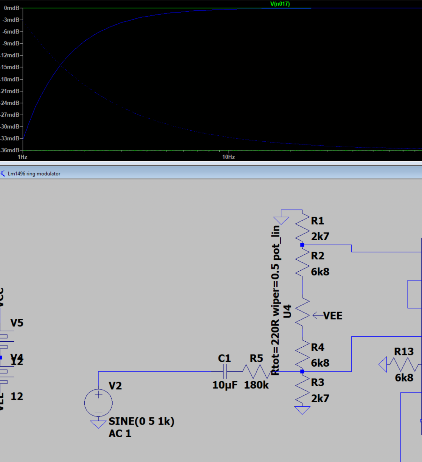
I simulated the frequency response for the input. A 1uF cap gives a 3dB point at around 1Hz.

As the cap is DC biased at 7.5V, its capacitance may in practice be as low as 0.1 to 0.2uF. It would then have a 3dB point around 10Hz.

If we use a 10uF cap instead, this would in the worst case have a capacitance around 1-2uF, matching the specified 1uF. If id is NOT reduced, a 10uF cap should have a 3dB point even lower than 1Hz and we should still be fine - I hope!
No comments:
Post a Comment