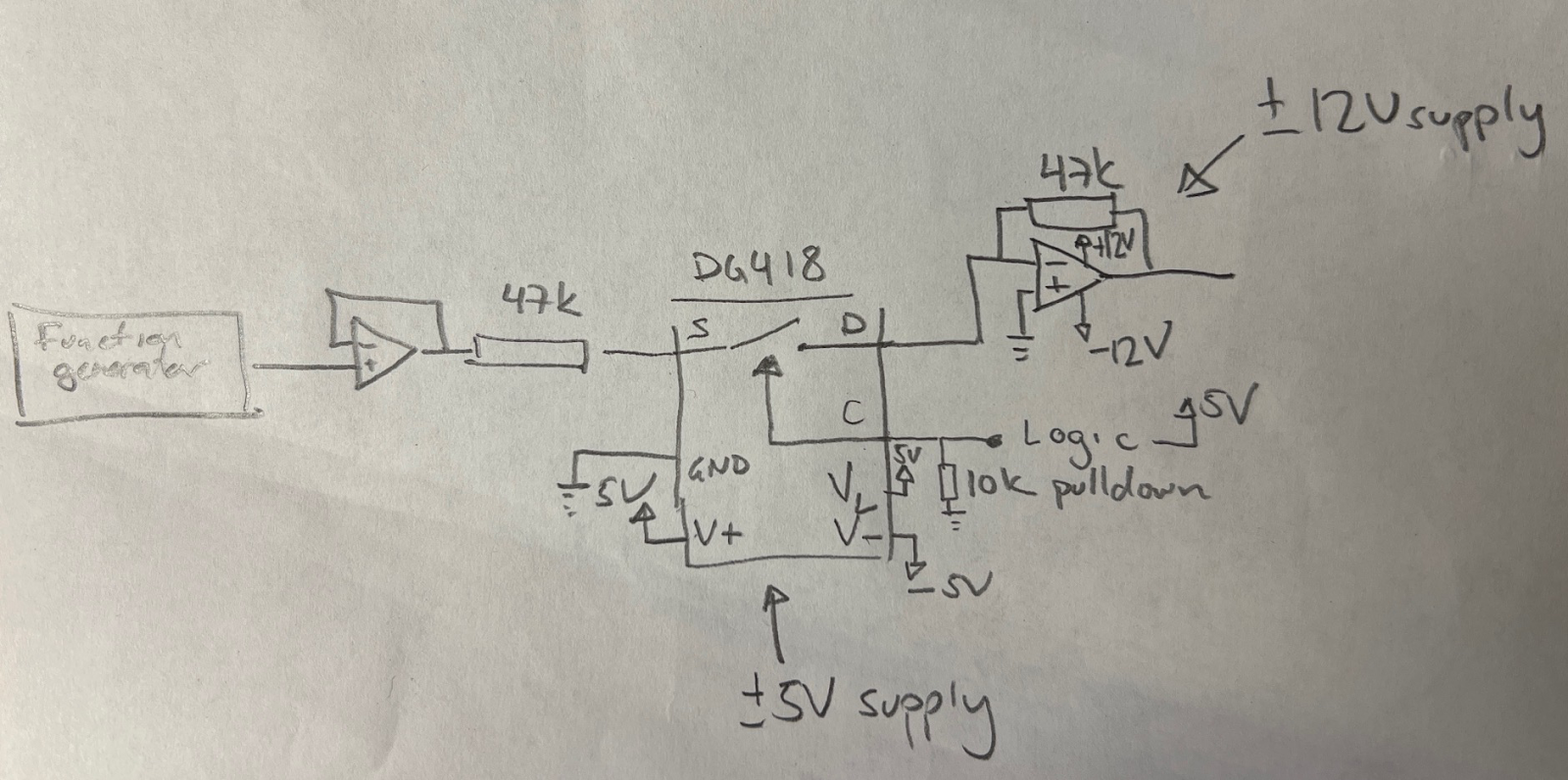
I hooked up a DG418 on a breadboard, and used an 78L05 and 79L05 to get a +/-5V supply for the DG418.
I then used a TL072 op amp with +/-12V supplies, with one op amp to buffer the input from the function generator and the second to "sum" (just invert really) the output from the switch, with a 47k negative feedback resistor.
 |
| Version of circuit where input resistor is before the switch |
I could now experiment with having the op amp input resistor BEFORE the switch (placing the switch at the virtual ground) or AFTER the switch
An initial test with a 10Vpp (+/-5V) signal showed that it worked in both configurations.
 |
| Resistor after the switch, 10Vpp |
 |
| Resistor before the switch, 10Vpp |
I then placed a 20Vpp signal on the version with the resistor after the switch. As expected, the switch clips the signal since it sees the full 20Vpp, but exactly how it clips is interesting. Measured at the input pin (i.e. the output of the buffer), the INPUT is clipped - the top is at 9.16V and the bottom at -5.85. I didn't expect it to be asymmetrical.
 |
| Resistor after the switch, 20Vpp. Output (and input) clips |
Next up, I moved the resistor to before the input. The switch should now see no voltage swing (though a current passes through, +/-0.2mV at its peaks). This also worked as expected, the output is also 20Vpp (though inverted because of the op amp configuration).
 |
| Resistor before switch, 20Vpp passes nicely |
This looked very promising. Next up was turning the switch OFF.
Again, for the 10Vpp signal, it worked as it should for both variations.
 |
| Switch off, 10Vpp |
I then tried cranking up the signal for the variation with the resistor before the switch, but then "disaster" struck: Once the input signal got higher than the DG418's supplies, it started leaking! With a 13Vpp input, it blocked everything up to 10Vpp. The remaining, however, was passed through, giving the output small "bumps"!
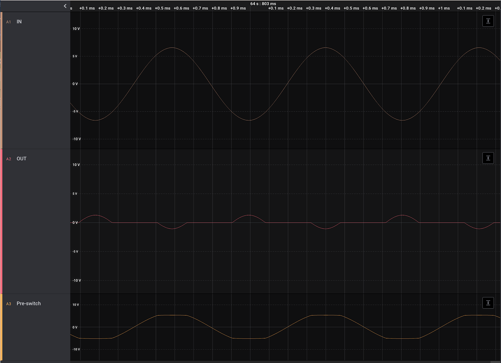 |
| Resistor before switch, switch off, 13Vpp. Anything above approx 5.1V is passed, giving funny little bumps on the output. |
When showing the result to ARabidSquid, he confirmed that this was how CMOS operate, it cannot block anything higher than it's supply voltages.
After seeing this result, I remembered that I read something similar yesterday - someone posted about a similar issue, where a current input made the switch leak when it was turned on. Someone suggested using an SPDT (or two switches in a crosspoint switch) to sink the current. This could be an option, to use a separate bus to sink all input signals that are not in use. However, I think I'd rather stay within the operating limits and keep my signals at 16Vpp max.
No comments:
Post a Comment