I've simulated both the Juno 106 filter (with 270pF caps) and the JP6 filter in 24dB LP mode, to figure out their response - what voltage (or rather current) to frequency rate to expect.
Quite interestingly, the two implementations track each other fairly well. Both have around a 30Hz per mA or 30uA per Hz response.
EDIT 26/12-18: It seems I've messed up a bit? (0.1V / 3300Ohm ) / 4 is not 7.57mA, it's 7.57uA. Thus the response is 30Hz/uA or 30nA/Hz?
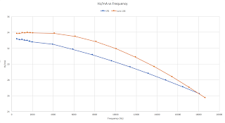
Also very interesting to note is that the response is not linear. The higher the frequency, the more current is needed for the same change in Hertz.
I measured the 3dB point at 16 selected currents:
The CV is the input to a constant current circuit. It is the voltage across a 3k3 resistor, and the resulting current (buffered to stay constant) is split between the four cells of the filters.
I selected 8 tightly spaced voltages and 8 further apart, as the lower end requires less change to double the frequency. Deltas are the difference between two measurements. F_c is the 3dB cutoff frequency point. This is a linear CV, e.g. without the exponential converter connected.
The result ended up like this:
Note that the y axis is truncated to get a better view of the effect. One would expect a linear response, but in fact, as mentioned, the Hz pr mA drops as the frequency increases. The Juno follows a sharper curve and even if it starts out higher than the JP, it drops below it at some point. In other words, the Juno linearity is worse than that of the JP.
So what does this mean? It means that the V/oct tracking of the filter is not perfect. It will be slightly more closed as one moves up the scale on the keyboard. I have read about this effect earlier, and the writer noted that it didn't seem to matter all that much. I guess a little difference is hard to hear when the base frequency changes a lot.


No comments:
Post a Comment