Tuesday, March 7, 2023

Filter FM and a dash of VCO linear FM research

It's time to hook up the FM inputs on the low pass filter.

I have an option to use both linear and exponential FM.

The most common option is exponential (v/oct) as this is readily available by mixing oscillator output with filter cutoff CV.

I found a nice post earlier about the use of both types but cannot find it right now, but here is a thread about linear FM at least:

https://modwiggler.com/forum/viewtopic.php?t=119415

FM off

I did initially design the FM input with two SPST (on/off) switches. This allows me to disconnect the input completely, as I was unsure how far down I could get the VCA to go.

Now I've done some calculations:

At 0V, the VCA has -80dB attenuation. That means that a 5V input signal would give a 0.5mV output.

If we've set the modulation to 1V/octave, 1 semitone would be 83.3mV, in which case 0.5mV = 0.6 cent. The input is bipolar (+/-5V) so the total change is 1.2cents.

For VCO tuning/tracking, I've assumed that a relative pitch change of about 3cent is at the limit of human hearing - and that's for VCOs. I think it is probably quite safe to use the VCA as a switch in this case. 

That leaves me with two options 

- either I use a DG413 as an SPDT switch, switching between lin and log - that saves me a single digital control signal. 

- or I use only exponential FM, in which case I don't need a switch at all.

I am currently breadboarding this. Both lin and exp FM works fine, but +/-5V linear FM seems to saturate something so the wave is cut off in some way. I will do a recording of it and add soon. Then I have to simulate the same to see what is actually going on. If I cannot make it work well I will just go for an exponential FM only.

Filter out: DCO1 is filtered, DCO2 modulates filter cutoff. Before red line: Linear FM, after: Exponential (v/oct) FM


Self resonance and exponential FM settings

Self resonancce and exponential FM output

Self resonance and linear FM output


Observations

Lin FM makes the filter "flatline". when the CV (DCO2) is low enough, the filter reaches a zero Hz cutoff, but the CV still goes lower, meaning the cutoff stays at 0Hz for some time - the filter does not support "through zero" modulation. 

PS: The output flatlines when input CV is positive, this is because the reference current is negative and any positive cv "negates" the reference current. Once the sum reaches 0 we cannot go any higher and the output flatlines.


Linear FM: When DCO2 is above a certain level,  the output "flatlines", presumably because cutoff reaches 0Hz before DCO2 reaches its peak.


Some measurements of linear FM CV vs I_abc

I_ref without any modulation is -12V / 1.2MOhm = -10uA (NB: mislabeled as -15V in captures)

With a +/-5V CV and a 120k input resistor, we will get 5V/120kOhm = 41.7uA, or approximately +/-4x the original I_ref. But since we cannot use an I_ref > 0, we get a flat line when the input from the linear FM CV reaches +10uA.


Cutoff CV: 0V, Lin FM CV: +/-5V


Cutoff CV: 2.5V, Lin FM CV: +/-5V


Cutoff CV: 3.5V, Lin FM CV: +/-5V


Cutoff CV: 4.5V, Lin FM CV: +/-5V


In my simulation I have written that we should use an input resistor that is approximately 10x the one used for the reference current, as that is what Yusynth.net uses for his VCO. That is not true.

Yusynth generates his reference current from a 5V source through a 1M resistor, giving a reference current of 5uA. For the linear FM input, he uses a 100k resistor, so a +/-5V input gives a +/-50uA output, which is 10x the normal reference current.

I, on the other hand, has used a CV that gives 4x reference current.


Cutoff CV: 0V, Lin FM CV: +/-5V, but this time we use a 50k lin CV input resistor


Calculations

To get a better feeling of the lin FM range I've done some simulations on the filter circuit. Here is the Frequency CV vs cutoff frequency vs I_control vs A/Hz (through a single cell):

1.0V:    10Hz    259nA    25.9nA/Hz

1.5V:    37Hz    1.03uA    27.8nA/Hz    

2.0V:    150Hz    4.18uA    27.8nA/Hz

2.5V:    604Hz    16.4uA    27.15nA/Hz

3.0V:    2.3kHz    63.6uA    27.7nA/Hz

3.5V:    8.2kHz    223uA    27.2nA/Hz

4.0V:    22.4kHz    639uA    28.5nA/Hz

4.5V:    42kHz    1.3mA    31.0nA/Hz

1.3mA is the highest possible value before we reach a flat top.


If we disregard the first and the last two (>= 4.0V) as we already know that they are not tracking that well, we get an average of 27.5nA/Hz


From my previous work I have that: 

R_linfm is often selected so that I_linfm = I_ref when linfm CV is at its highest (often 5 or 10V), which means that the frequency can be modulated by +/- 100% (the reference current will be between  0V and 2 * I_ref).

This is only true as long as we do not use through zero modulation. 

Also, looking at the Yusynth VCO with its 10x FM, this is clearly not what everyone does.


What are others doing. VCOs:

Rene Schmitz: 

https://www.schmitzbits.de/vco2.html

VCO 1-3: 15V / 1M ref current, 5V / 220k lin FM (15uA vs 23uA, ca 1.5x mod)

VCO 4 (TZFM) 15V / 470k ref current, 5V / 220k lin FM (32uA vs 23uA, or 0.72x mod)


Yusynth VCO

https://yusynth.net/Modular/EN/VCO/index.html

5V / 1M ref current, 5V / 100k lin FM (5uA vs 50uA, or 10x mod)


CEM3340

Pin 13 on the CEM3340 is the reference current summer. The datasheet has a 1.5M resistor to 15V and a 1M + 0.1uF cap to lin FM. In the last paragraph of the datasheet it says "The value of the input resistor should be selected so that the maximum peak to peak input signal produces a plus and minus current equal to the reference current". This is exactly what I have written in my own research on VCOs, so I guess this is where I got it from (?).

15 / 1.5M ref current, 5V / 1M lin FM (10uA vs 5uA, or 0.5x mod. Or, could it be they expected a +/-10V lin FM CV? In that case they follow their own doubling rule.


Ian Fritz

https://ijfritz.byethost4.com/sy_cir2.htm

6.9V / 690k ref current, 5V / 100k lin FM (10uA vs 50uA, or 5x mod)

https://ijfritz.byethost4.com/sy_cir16_teezer.htm

Hard to tell as lin FM is done differently


MFOS

https://hackaday.io/project/47158/gallery#ecedc0e5555ada3907345e3c0c4cda3d

A bit hard to tell, lin FM enters through the middle of a voltage divider??

12V / 1M ref current, 5V / (1M || 100k) lin FM (1M til summer) 


JJ Clark

https://electro-music.com/wiki/pmwiki.php?n=Schematics.XR2207VCOByProfessorJamesJClark

12V / 68k ref current (!), 5V / 10k lin FM (176uA vs 500uA, or 2.8x mod)


Thomas Henry

https://electro-music.com/wiki/pmwiki.php?n=Schematics.ACD4046BasedVCOByThomasHenry

15V/1.5M ref current, 5V / 100k lin FM (with AC/DC switch) (10uA vs 50uA, or 5x mod)


Lots of VCOs here: 

https://electro-music.com/wiki/pmwiki.php?n=Category.VCO


Ken Stone CGS48 VCO and VCF-ish thingie with built in VCO

https://electro-music.com/wiki/pmwiki.php?n=Schematics.Bi-N-TicFilterByKenStone

https://sdiy.info/wiki/CGS_VCO

15V/150k ref current, 5V/100k lin FM (100uA vs 50uA, or 0.5x mod)


Linear FM and "amplitude" in Hz

As described in more detail here, increasing the base frequency also increases the "amplitude" of the modulation (if you think about the FM as a bipolar signal). The higher you get the larger the change is. 

So, what to choose

That's the hard question, isn't it... Right now I'm having a hard time understanding why anything more than a 0-to-doubling of the reference current is used on a non-through-zero FM VCO/VCF. Once we go lower than 0 the average frequency starts to drop and the VCO goes flat. I guess that's an effect as well, but why do we want it? And why on earth would we want 10x the input as is the case on the Yusynth VCO? Hmm.... I guess the only way of finding out would be a proper test.

Update: After a little thinking I think (...) I will try this: Select an R_linfm that gives a I_linfm that is 4x the reference current. That way I can just divide the CV by four (= shift right 2) to get an I_linfm equal to I_ref, meaning that the output of the exponential divider will never be below 0. 

Juno filter FM

Incidently, for the juno filter with a 10uA I_ref, this whould mean a 125k resistor. My current design uses a 120k, which gives a 41.7uA max, or 10.4uA after division by 4. This is very close to the ideal. One could argue that a 130k would be better, making us not quite reach I_ref, but again, it's better to test. It is also possible that a 5V input to the VCAs does not give exactly a unity gain, so 120k, being a standard resistor value, may be good enough anyway.

VCO lin FM

As for the VCO, we have a slight issue. My current design expected a 15V input using a 1.5M resistor, giving a 10uA I_ref. Now, hopefully, I'll be able to tune away the difference, but selecting the proper R_linfm depends on whether I match it with the current design or with a possible updated/corrected design. Anyway, here are the two options:

For 10uA, I could use the same 120k or 130k resistor as for the juno VCF.

For 12V / 1.5M = 8uA i will need 32uA. The correct value would be 156k. The closest standard value is 150k which gives 33.3uA - again, a little high (3.5% vs 4% for the juno filter) but it may work anyway.

Jupiter 6 filter lin FM

This uses the same expo converter as the juno filter. Right now they both use 15V and 1.5M R_ref, giving an I_ref of 10uA. As I've already redone the Juno filter for 12V with a 1.2M R_ref I will probably do the same with the JP6 version. That means that I can use a 120-130k R_linfm here as well.

Moog filter lin FM

The current 15V version has a 1M R_ref, giving I_ref = 15V / 1MOhm = 15uA 

If we switch to an 800k version (or 820k perhaps) for the 12V version, we will keep the I_ref the same.

I_linfm would then be 60uA and we would need an 83.3k resistor.

If we continue using the 1M R_ref, I_ref would be 12uA. I_linfm would be 48uA and we would need a 104k resistor


Thursday, March 2, 2023

Frequency modulation

While testing filter FM I realised that I needed to know a little bit more about what is actually going on, so here we go. I'll explain things using VCO frequency modulation as it is a bit more intuitive, but the same happens with filter FM.

Linear FM

In linear FM, the change in Lin FM CV is directly propotional to the change in frequency. For example, if a 1V increase in Lin FM CV leads to a 200Hz increase, a 1V decrease leads to a 200Hz decrease - as long as the base frequency set by the (1V/oct) Pitch CV stays the same. 

In other words, if the initial frequency is 440Hz, the output should be between 240Hz and 640Hz. What we hear is close to the average of the two extremes (this moves into the field of psychoacoustics apparently, so this is not an exact science or at very least not something I'm proficient in). The average here, at least with a symmetrical waveform, is 440Hz, so the output stays in tune as we increase/decrease the CV.

BUT: Once you change the Pitch CV, 1V no longer corresponds to a 200Hz increase. However, increasing and decreasing the Lin FM CV will add or subtract the same number of Hz so the average stays the same as the base frequency. Also, the relationship between the modulated frequency in both cases to the base frequency stays the same.

For example - if a 1V Lin FM CV adds 200Hz when the base frequency is 440Hz, adding 1V will add 400Hz (one octave up) when the base frequency is 880Hz (one octave up), and 100Hz (one octave down) when the base frequency is 220Hz (one octave down). 

Linear FM stays in tune both as we change the FM CV and the Pitch CV, as long as the modulated frequency does not reach either 0Hz or the upper limit of the VCO pitch or filter cutoff.

Linear FM is usually implemented by modulating the reference current in the exponential converter.


Exponential FM

With exponential FM,  we modulate pitch as "semitones". If we use a 1V/oct input, and FM CV is, say, +/- 1V, frequency will go between +1 and -1 octave of the original frequency. For example, if the original frequency is 440Hz, the modulated signal will go from 220Hz to 880Hz.

What is the effect of this? Well, what we hear is not the original 440Hz tone, but again closer to the average of the two extreme. In our case this means 220 + (880-220)/2 = 550Hz

If we drop the original pitch by an octave to 220Hz, we would expect an output between 110 and 440Hz. The average is now 110 + (440-110)/2 = 275Hz, which is one octave down from 550Hz. In other words, the modulated output tracks the original pitch.

But what if we change the FM CV? If we go from +/-1V to +/-2V but keep the original frequency at 440Hz, we would now get a range of +/-2 octaves, or from  110Hz to 1760Hz.

The average of these is 935Hz, whereas for the +/-1V FM CV it was 550Hz. The perceived pitch increases. Similarly, if we decrease the CV the perceived pitch drops. As long as the CV range stays the same we're good though.

Exponential FM is usually implemented by mixing the FM CV with the normal V/Oct CV.


Through zero modulation

An exponential FM will always halve the cutoff frequency for every 1V decrease of CV. This means that the cutoff frequency will never reach zero.

For linear FM however, which controls the reference current in the exponential converter, cutoff WILL reach zero. 

Through zero modulation means that we detect when the CV changes polarity, and (at least for a VCO) reverse the polarity of the output. The frequency should be the same as for a positive CV of the same magnitude. In other words, we use the absolute value of the CV for frequency, and the sign to control the output phase. I am not sure how this will work for a filter but it will be interesting to test.

A bit of maths for the linear FM case

The output current of the exponential converter, which linearly controls the VCO pitch, is defined as

I_c = I_ref * e^(-V_b/V_T)

where -V_b is the exponential CV presented at the exponential converter (scaled down from 1V/oct)

Let's call E = e^(-V_b/V_T), giving us

I_c = I_ref * E

Now, say we increase I_ref with a current I_linfm that is 50% of I_ref. We now have that

1.5 * I_ref * E = 1.5 * I_c

In other words, we increased the pitch by 50%

The absolute increase in I_c is 0.5. 


Now, let's double E, going one octave up

I_ref * 2 * E =  2 * I_c

Again, we increase I_linfm by 50%:

1.5 * I_ref * 2 * E = 1.5 * 2 * I_c = 3 * I_c

We have still increased the pitch by 50%, but this time the absolute increase in I_c is 1. In other words, doubling E doubles the effect of changing I_ref. 


Substituting with numbers: Let's assume that E gives us an I_c that produces 440Hz

increasing I_ref by 50% would then produce a 1.5 * 440Hz = 660Hz wave. The change in Hz is 220.


If we double E without changing I_ref, we get an 880Hz wave.

Now if we increase I_ref by 50%, we get 1.5 * 880Hz = 1320Hz. The change in Hz is 440.


Comparing the two, we see that an increase in E makes a change in I_ref span more Hz. We also see that the relationship between the changed pitches - 660Hz and 1320Hz (2x, or one octave between), is the  same as the change in E.


Some sources

https://ask.video/video/fm-synthesis-explored/3-3-exponential-vs-linear-vs-thru-zero-fm

difference between linear and exponential applications: https://modwiggler.com/forum/viewtopic.php?t=52340

Exponential FM vs linear FM: https://gearspace.com/board/electronic-music-instruments-and-electronic-music-production/1100357-exponential-fm-vs-linear-fm.html

Understanding the Differences Between Exponential, Linear, and Through Zero FM: https://learningmodular.com/understanding-the-differences-between-exponential-linear-and-through-zero-fm/

Adding through-zero lin fm to CEM3340:

http://jhaible.com/legacy/tonline_stuff/hj2vco.gif

http://jhaible.com/legacy/tonline_stuff/hj_modul.html

SSI2130 VCO with TZFM

https://www.soundsemiconductor.com/downloads/ssi2130datasheet.pdf

SSI2130 TZFM control circuit


The SSI2130 has built-in time reverse that changes the direction of the waveforms. This little circuit both outputs the absolute value of the lin freq FM and a control signal for the direction control ("time reverse")

Thursday, February 16, 2023

Temperature sensing

I intend to place a few temperature sensors around my circuits to try to make calibration easier.

I've already bought an LM75AD that I intended to use for the VCO, that's an I2C device and can easily be put on the I2C bus I have on the Teensy.

For the filter modules I don't really want to put anything digital alongside the analog circuitry, so today I found a passive option - the MCP9700/9701, of which the MPC9700 is the cheaper and good enough. It's a simple device that outputs a voltage depending on the temperature and is built specifically for use with 8 or 12 bit ADCs.

The absolute accuracy is rather poor, but relative accuracy and hopefully repeatability is within 1degree C. As I don't need to know exactly what temperature we're at - I only need to store a lookup table for a few measured temperatures and interpolate between them, this should be good enough.

I will have three filters on the analog board, so being able to multiplex the voltage output to a single pin on the Teensy is a good idea. I was thinking that I could even combine it with the calibration input that is multiplexed from elsewhere in the analog circuit.

Here is a short example for how to connect it to an arduino:

https://startingelectronics.org/beginners/arduino-tutorial-for-beginners/measure-temperature-with-arduino-and-mcp9700/


And a note about how to increase the accuracy, though this is too complex to use I think

http://ww1.microchip.com/downloads/en/Appnotes/00001001C.pdf

Tuesday, February 14, 2023

Filter CV range calculations

Update: I've used 17.9mV throughout this post as the V/oct input to the exponential converter. Not sure where I got this number from, but in my posts on temperature compensation I use 17.5mV per octave at 20C. The change in range per degree is approximately 60uV. This places 17.9V 0.4mV or 400/60 = 6.67 degrees up, at 26.67C. I've recalculated things and it doesn't really change anything except for the tracking so I've left this post as is. 

Now here's the fun part of the last post :-) 

I did a quick measurement of the input CV to the exponential converter.

For an output of 150nA we need an input of 72mV

For an output of 1.16mA we need an input of -149mV


This means we have a total range 231mV. With the expected 17.9mV/octave this covers 12.9 octaves. If we want to cover 14 octaves, we need 17.9 mV * 14 = 250.6mV.

It looks like 14 oct may be hard to achieve in practice, as < 150nA will give an output that always attenuates, and one additional octave when we're at 1.16mA would need 2.32mV which is much more than the max we're able to generate. But for the sake of this discussion, let's go for a 14V range, starting at 72mV.

We then want to add +/-3 octaves of tuneability, to cover temperature changes and parts differences. Normally, these 3 octaves will be useless, but being able to change the input voltage by a similar amount will give a voltage at the expo converter that is +/- 3*17.9mV.

To cover this, the range seen at the expo converter should have a range of 17.9mV * 20 = 358mV. It should start at 72mv - 3 * 17.9mV = 125.7mV and go down to -232.3mV

We know that the maximum output of the CV summer is around +/-10V with +/-12V rails. That means that if we set -10V out of the CV summer to end up as -232.3mV, we need an 1/43 attenuator.

Selecting a nice and round number for the attenuator, 1/40, we would need -9.25V in to reach -232.3mV

That would put the top voltage at 5.03V, giving a range of 5.03V - -9.25V = 14.28V

ok, so that is the MOST we can do. But let's pick a number that is easier to work with. Let's restrict the output of the CV summer to a range of 10V. Having a 0-5V CV input (that should cover 20 octaves) means we can use a -2x gain, that's pretty neat.

So, with a 10V range in, and a 358mV range out of the voltage divider before the expo converter, we need a 10V/0.358V = 27.93 attenuation. We already have a 560Ohm tempco at the bottom of the divider. Picking a 15kOhm resistor at the top will give us a 27.78 attenuation, that's pretty close - it gives 360mV out for 10V in.

Applying this to the original output values gives us:

Needed input top: 125.7mV * 27.78 = 3.49V

Needed input bottom: -232.3mV * 27.78 = -6.45V


So - we need a circuit that produces a 0 to -10V output from a 0-5V input, and then offsets that output by 3.49V

We already know that the first part is achieved by a -2x gain. Using a 100k feedback resistor we could use a 50k input to achieve that.

For the 3.49V we connect a resistor to -12V. The gain has to be 3.49 / -12 = -0.2908. With a 100k feedback resistor we thus require a 344k resistor. 

The nearest standard value is 330k or 360k if using a more fine grained scale. Using a 360k resistor will give a gain of 100 / 360 = 0.278 and an output of 3.33V. A 330k resistor gives a gain of 100/330 = 0.303 and an output of 3.64V. Let's go for the 360k first, just because -3.33(3333)V is such a nice number. The range at the input is now 3.33333V to -6.666V (mmmmm!).

Converting back to the output at the expo converter, we get 3.33/27.78 = 120mV and -6.66/27.78 = -240mV. 

If we instead go for the 330k resistor, it would set the range at 3.64 / 27.78 = 131mV to -6.36 / 27.78 = -228.9mV

Now, none of these cover the entire range we originally wanted. The 360k resistor is 5.7mV away from reaching the lowest point, the 330k resistor is 3.4mV away from the highest point. The worst offset is thus about 0.31 octave away from our intended range. As we have 3 octaves to work with in both directions, I'd say both options will work.

Backtracking a bit more, we get that our new range, 360mV (for the 360k resistor, or 359.9 for the 330k resistor), covers 360mV/17.9mV = 20.11 octaves. That's fairly accurate without any kind of tuning, which is a very good starting point!

To sum it up:

Use a 50k resistor between CV input and the negative op amp terminal

Use a 100k feedback resistor

Use a 330k resistor between -12V and the negative op amp terminal

Use a 15k resistor on top of the voltage divider (connected to the op amp output)

Use a 560R resistor to ground at the bottom of the divider

NB: 15V/-15V supply is really 12V/-12V, I just couldn't be bothered changing the labels.

Update:

When using 17.5mV the range is instead 124.5mV to -229.5mV. 20 octaves would be 350mV. Using a 0-10V input to the resistor divider would give perfect tracking for a 28.57 attenuation, which would require a 15.44k resistor on top.

If we keep the 15k resistor we will get 0.486V/octave instead of 0.5 at the input. It doesn't matter too much as we have a lot of tuning range, though we COULD combine a 15k and a 470Ohm resistor if we wanted to.

Now it's time to test this. Quick Batman, to the LTSpice-mobile!

(We have one last issue to tackle though, temperature compensation. But let's not spoil the fun yet!)


Edit: testing

Red: CV input, Blue: CV summer output, Green: I_abc

My calculations are correct. I see a 3.64V to -6.36V output after the CV (With a 330k offset resistor). 

The voltage at the expo converter is 130.87mV down to -161.3mV, after that it flattens out meaning we've reached the limit of the converter at its 25C state (we needed it to reac -149mV for a 1.16mA current so that's ok). This happens when CV is 4.44V btw.

I_abc is 15nA to 1.28mA.

Light blue: expo converter base voltage, Green: I_abc

We do see a bit of non-linearity when the expo converter base voltage reaches around -122mV (CV is around 3.6V). Not sure what is going on there, I saw the same thing with the unchanged circuit. It would mean that the last octave (-122mV to 149.9mV) is not tracking properly, though this either should not be a problem because it is so high anyway, or we have a bit of room to calibrate it out. 

Frequency response

I did some fairly manual frequency response measurements, plotting the filter response for various CVs and reading the -3dB cutoff frequency. It's not entirely accurate but gives a good indication:

CV: Frequency

0.75V: 3.48Hz (oct 0, but never gets above -2.2dB)

1.00V: 8.6Hz (oct 1)

1.25V: 17.9Hz (oct 2)

1.50V: 36Hz (oct 3) "Baseline" for expectations later

1.75V: 74.33Hz (oct 4)

2.00V: 150Hz (oct 5)

2.25V: 304Hz (oct 6)

2.50V: 606Hz (oct 7)

2.75V: 1.21kHz (oct 8)

3.00V: 2.34kHz (oct 9)

3.25V: 4.47kHz (oct 10)

3.50V: 8.20kHz (oct 11, expected 9.2kHz)

3.75V: 14.1kHz (oct 12, expected 18.4kHz)

4.00V: 22.34kHz (oct 13, expected 36.8kHz)

4.25V: 32.8kHz (oct 14, expected 73.7kHz)

4.50V: 41.9kHz (additional octave, highest reachable cutoff)

As we can see, tracking is quite accurate from between oct 1 and 2 up to between octave 10 and 11. We will be able to tune in 40kHz as well, with an additional 0.5V CV (=2 octaves) left for temperature compensation etc, meaning we can get a workable 4Hz to 40kHz.

PS: Since it looks like the most compensation is needed at the top range, we could perhaps go for the 360k shifting resistor option instead, it will shift everything up by about 2/3 octave and allow more calibration on top.


Temperature compensation

We're using a 560Ohm tempco. Let's see what PPM rating it should ideally have. Now, tempco values are usually defined with a 0% change at 25 degrees. At 25 degrees, we would expect the expo converter to need 17.5mV + 5 * 0.06mV = 17.8mV per octave. Let's calculate the necessary input voltage:

V_in * 560 / (15000+560) = 0.0178V, V_in = 0.494V

Now, if the temperature rises by 10 degrees, we would need 17.8mV + 10 * 0.06mV = 18.4mV for the same change. To keep the CV input equal, we see that

0.494 * x / (15000 + x) = 0.0184V

x = 580.32Ohm. In other words, the resistance needs to change by 20Ohm or 0.5Ohm per degree.

From my previos work I have that

560 * (1 + x * (10^-6)/10) = 580

x*10^-6 = 580/560 - 1

x = (580/560 - 1) / 10^-6 = 3571

Which should mean that the resistor should have a 3571ppm/C temperature coefficient.

The ones I have, Vishay Linear PTC, TFPT0805L5600FV (684-1021 from RS components), are nowhere near this. They are 4110+/-400 ppm/K, and a simple example says they are expected to be 560 * 1.042 = 583.52 at 35 degrees. The worst case scenario should be 1.046, = 585.76, let's round to 586. While this may not be good enough for a VCO, I think it has a fair chance of working for a VCF. Let's calculate.

The output of the voltage divider at 35 degrees should be near

0.494V * 586 / 15586 = 18.57mV, or 0.17mV off from what we expected.

At 35 degrees, a semitone is 18.4mV / 12  = 1.533mV. 0.17mV equals 11cents of error. Over a 14 octave range, the accumulated error will be 155 cents or 1.5 semitones. 

If instead the temperature rose by 25 degrees to 50C, the resistor should be at 1.110 * 560 = 622Ohm. The needed output would be 17.8mV + 0.06 * 25 = 19.3mV. The output from the divider would be 19.67 or 0.37mV off, equaling 24 cents, and over 14 octaves 338 cents, equaling 3.5 semitones.
Without temperature compensation

To get a better understanding of what we are up against, let's see what the offset looks like if we don't use a tempco.

Starting again at 25 degrees, we know that 0.494V in gives 17.8mV out.

But then, at 35 degrees, it STILL gives approximately 17.8mV out, while the exponential converter needs 18.4mV. We have a 0.6mV error instead of the 1mV we would get with the tempco.

Over 14 octaves that accumulates to 8.4mV or 5.5 semitones - or almost half an octave. This is for a 10V change. If the change is more drastic, say 25 degrees, the error will be 0.06 * 25 = 1.5mV/oct for a total of 21mV, or 1.14 octaves. As we have a +/-3 octave tuneability, this should also be within reach. We would, however, need to know the temperature!

Keeping multiple VCFs tracking

With a tempco in place, and assuming that it is somehow affected at least not too much differently than the internal temperature of the expo converter, and also assuming that the VCFs won't drift THAT much from each other in terms of temperature, say +/-5 degrees, we COULD see as little as 0.38 semitones difference (given all VCFs are tuned to the middle freq, we would see a +/-7 oct range to drift in). This would not be perceptible in terms of cutoff but perhaps for resonance. 

WITHOUT the tempco, we have different option - measuring temperature and keeping several lookup tables. Apparently, this is what some Sequential synths do their VCO calibration, making them playable without warmup. 

We would however need a temperature sensor close to the expo converter. It is an exciting thought and I should definitely explore it further, especially seeing as thermistors are hard to get, expensive (2-3USD per chip) and have to be manually soldered.

It may even be an idea to use a temperature sensor for tuning the filters even with the thermistor in place...

A thought about tuning

I started wondering about how to best tune the cutoff. We can send a sine-like wave and see how it is attenuated. This will work up to the maximul DCO frequency which is something like 20kHz, but above that, in the most troublesome territory, we have no built-in source (though we could possibly use a VCO, but they are themselves not completely stable).

But we DO have resonance. If the resonant frequency is directly and proportionately related to the cutoff frequency, could we measure the resonance wave (e.g. just frequency counting) instead?

Monday, February 13, 2023

Tuneable filter with 14 octave span

I intend to make the juno filter tuneable in software. To do this, I hoped to add a 20 octave range to the CV and just use that. But simulating the filter gave a few surprises:
- when using a 25k input resistor to get 20 oct range, the output of the initial op amp exceeds the rails, so it will clip.
- the maximum cutoff for the filter at the current implementation is around 48kHz
- Below 7-ish Hz the filter acts like a band pass filter so the input is always attenuated, meaning lower frequencies are not possible.

Now, the two last facts are not a big problem. They happen on the filter side of the exponential converter, which is not as temperature sensitive so range hopefully won't change that much with temperature.

The expo converter however will change a lot, meaning the input needed to get a certain output will not stay the same. THIS is where we need to apply tuning relative to temperature.

So what I need to look at is the circuit before the expo converter transistor pair. I need to make sure that THAT can go above and below what is needed for control at 25 degrees celcius. To do this I've started out mapping out what currents into the filter core gives what cutoff. Here is a short table:

2mA = 47.2kHz
1.5mA = 45kHz
1.2mA = 43.5kHz
1.1mA = 42.5kHz
1.0mA = 41.5kHz
0.8mA = 38.6kHz
0.7mA = 36.5kHz
0.6mA = 34.2kHz
0.5mA = 31.3kHz
0.4mA = 27.3kHz
0.3mA = 22.5kHz
0.2mA = 16.3kHz
0.1mA = 8.7kHz
50uA = 4.4kHz
25uA = 2.23kHz
12.5uA = 1.11kHz
6.25uA = 553Hz
3.125uA = 274Hz
1.56uA = 136Hz
781nA = 67.4Hz
390nA = 33Hz
195nA = 16Hz
97.7nA = 7.64Hz
48.8nA= n/a, alltid under -3dB

So... from around 100nA and up to 0.2mA, the tracking seems to follow the rule of doubling the current = double the -3dB cutoff point. After that it falls off a bit. I think that a range of approx 4-40kHz is fine, that's about 13.5 octaves. 

That means that the input range we're looking for is about 100nA to 1.2mA. Next up will be looking at the circuit as it is and see what the input to the expo converter is at these currents. Then I'll see if I can change how the circuit works to allow the input to go lower and higher than this. At a stable 25degrees this won't have any impact (it simply won't work), but it will allow us to correct for changes later. Maybe.

A bit more testing

I did some more measuring and calculations today. First of all, I calculated the necessary resistor to get 1V/oct response. The Juno uses a resistor voltage divider with a 560Ohm tempco at the bottom. To get 1V in = 17.9mV out (17.9mV is the magic number for expo converters at 25C), the top resistor needs to be 31.745k to get perfect tracking. In the current design this is achieved by a 20k multiturn pot combined with a 10k and 8k2 resistor. 

In the 12V version of the filter, we have a few issues.

Without any changes, Iabc tops out at 1.07mA. We need at least 1.16mA to reach 40kHz.
Allowing a 20V input (or rather, changing to a 25k input to get 20 octaves from 5V input) will not work as the cv input opamp output will hit the low power rail (-12v) before going all the way.

So, what can be done:

1) By switching the 10k input resistors on the LM13700 Iabc inputs for 8.2k ones, we get a max Iabc of 1.3mA

2) By decreasing the top resistor in the resistor divider, we can get a response that is lower than 1V oct, for example 0.8V/oct. This means that the range output by the cv input summer can be within the power rails. 

I did some inital trials without calculating too much. For easier reading I use a 0-20V CV input with a 100k input resistor. Swapping R34 with a 5k (reducing the top resistor by 5k) and replacing 10k Iabc resistors with 8.2k, I get a CV AFTER the summer that goes from 6 to -10V (at 15.6V input). The Iabc response goes from 25nA at 0V to 1.3mA at 14V. 150nA, which we know from earlier is about the lowest we need, is output at 2V input. 

20V CV input and around 0.8V/oct tracking. +/-12V filter

Red: CV input, Green: Voltage after summer, shows saturation at around 16V CV. Blue: I_abc, tops out when CV is around 14V.


This means that our useable range is around 12V, from 2V to 14V, and that we have around 2V above and below this. We already have a fairly useable tuning range.

So, what should I do next?

Given 20V in and 100k input res (will be changed to 5V/25k)

1) Find the range we need for 14 octaves (150nA to whatever)
2) Find a gain + resistor divider that puts 3 V in at 150nA and 17V in at whatever is needed for 14 octaves up.
3) Input summer must not saturate, eg. stay within +/-10V output for the full range.

This will be fun!

BUUUT. What about the tempco resistor? Will it still adjust itself correctly when the top resistor is no longer the same? Well, that needs to be checked. 

And for later: At what input audio does the filter start to distort?

EDIT: Input to expo conv: 72mV in = 150nA out, -159mV in = 1.16mA out

Thursday, February 9, 2023

Distortion 1.3 (?)

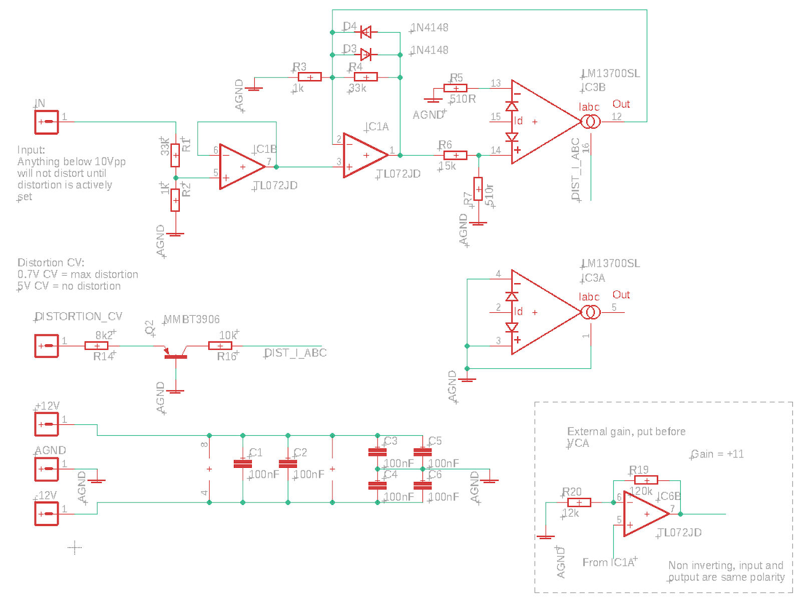
So after all the distortion testing, I've landed on a very simplified circuit:


This one only does soft clipping, but with a very reduced parts count compared to the soft/hard one.
It has no VCA and no switching, and CV control is simplified (which means that the upper 0.7V of the CV is not effective due to the voltage drop across the transistor, but it saves an op amp.

I had hoped that I could connect the output of IC1A directly to the VCA through a < 4.7k resistor, to make the VCA into a gain stage, but that introduced too much non-linearity into the equation. We need to use the non-inverting amplifier in the lower right corner, but it can be placed externally to save space on the distortion board. If we choose to have it on the board we should also reintroduce the CV circuit from the previous distortion to make cv 0-5V again.

Bottom: Output of VCA shows that the almost linear triangle input has been distorted. This is when connecting the output of IC1A directly to the VCA through a 3k3 resistor.

When using an op amp gain stage in between, most of the non-linearity is gone. What is left is introduced by the distortion circuit, see the output above.


Sunday, February 5, 2023

Distortion again

After discovering that my hard clipping circuit introduced a lot of noise on the gnd line, I decided to put a 1k resistor before the clipping diodes. When doing soft clipping, this put the 1k inside the feedback loop, but this didn't seem to matter too much.

However, now the soft and hard clipping modes are very similar, to the point that I wonder if it is really necessary to have a hard clipping mode at all.

Soft clipping, four diodes and 1k in feedback


Hard clipping, two diodes


Hard clipping, four diodes

Now, it's very hard to tell the difference with a sine input, so perhaps I should redo this with a more discrete function to see how it actually performs. But more importantly, I should try this out in practice.

Soft saw(ish)


Hard saw(ish), two diodes

Soft triangle


Hard triangle, two diodes

Soft triangle, two diodes

If the conclusion is that hard and soft clipping is too similar, I may also look at ways of improving the soft clipping to keep amplitudes more the same without having to compensate in the output VCA.

Update:
TWO diodes soft clipping is much less similar, perhaps that's the reasonable option - only two diodes for clipping

Here is a +/-5v with matching soft and hard clipping - without any amplitude compensation:

The output ends up at around 7v in both cases, which is pretty cool. We COULD trim it down to 5v again but we could also just leave it.

Now, there is ONE problem with all of this - the input will only distort if less than +/-5v. Once we start summing oscillators stuff we'll get distortion from the get go. Not sure exactly how to handle this as we want to be able to get distortion from a single osc too, so perhaps this is better solved in dry/wet mixing? If not, we need to attenuate the input further or use an input gain vca which i REALLY don't want to do, especially if we have an output VCA as well (we do already have two output VCAs so it may be solved in software though).

Update 2:
I did a change of the circuit to use a 68k/1k resistor divider instead of a 33k/1k, and to compensate for this I put a 240k feedback resistor in place of the 120k at the output gain stage to keep unity gain.

Now 10V is allowed through the circuit undistorted. When I send +/-5v through, distortion starts at around 50% turn of the CV pot. For +/-10V it starts at around 25%. 

With the output gain at max distortion set to get a +/-10V distorted output for a 10V input, I get a +/-8V output for a soft clipped 5V, so a significant gain. For hard clipping it is even more, the clipping level is around +/-9v for 5v input (though the slope is likely not as steep.

Again, I need to try this in practice to see what feels best.

+/-5V input with max soft clipping

+/-10V input with max soft clipping

+/-5V input with max hard clipping

+/-10V input with max hard clipping

In practice the big difference is that with the 10v pass option we may actually end up clipping against the +/-112v rails if we don't carefully adjust the gain through the cycle.

With the 5v pass option, we clip much sooner, and the max output is much lower. It can never reach 10V even if the input is 10V.

All in all it DOES look like the 5v version performs fairly well. Without any gain correction - and the gain CV set to about 3.3V, we do get a bit of gain for the 5V input as distortion increases. For 10v there is a bit of distortion from the start, more for hard than soft clipping.

Soft clipping, 5v in, no distortion

Soft clipping, 5v in, max distortion

Soft clipping, 10v in, no distortion set gives a bit of distortion on output

Soft clipping, 10v in, max distortion gives a higher output than for 5v max distortion.


Hard clipping, 5v max distortion

Hard clipping, 10v max distortion, not much higher than for 5v

Hard clipping, 10v no distortion. Distorts from the start, and more than for soft clipping


Modified circuit with unity gain at max vca cv (or without cvm just a buffer).


High frequency filtering in audio output

One thing that I've put off for a long time is selecting filter caps for various op amp output drivers. 

Today I had a look at some datasheets to figure out what others are doing. 

Generally, it seems that filtering (by putting a cap in parallell with the feedback resistor in an inverting op amp) is only done at the last stage of the circuit, not within the circuit itself. It seems that very little filtering is done except for biasing using electrolytics in the audio path to center the signal. I assume the final filtering is just to stop radio frequencies, stuff that we don't want to escape the circuit perhaps?

Here is what I found

Self on audio (book) page 237: 100pF/4k7 = 339kHz

Self on audio (book) page 359: 27pF/10k = 589kHz

JP8 source mix: 10p/100k = 159kHz

JP8 VCA cont 15p/100k = 106kHz

Juno 6 out: 47p/3k3 = 1.02MHz - See juno 60 where the 3k3 is actually crossed out in the schematics and 27k written instead.

Juno 60 out: 47p/27k = 125kHz

Juno 106 out: 22p/33k = 219kHz - Interestingly enough, and supporting of my theory that filtering only happens at the last stage, the 106 has the same feedback resistor as the Juno 6 (3k3) right after the filter, but no cap, as it has a mixer at a later stage too, mixing in High-pass filter.

JX-3P out: 330p/10k = 48kHz

JX-8P synth mix: 100p/47k = 33.8kHz

JX-8P chorus: 100p/22k = 72kHz

THAT4301 reference: 47p/20k = 169kHz

Sooo, I can't say that the findings are exactly conclusive. Before starting this research I suspected that the cutoff would at very least be above 22kHz (being the upper limit of human hearing) and perhaps at least the double as we want to make sure to not remove anything wanted. Most of these results seem to support that, with roland ranging from 33kHz up to 219kHz (disregarding the Juno 6 which seems to be too high). I'd say somewhere between 100 and 150kHz is probably a nice compromise.

Now, I started looking at this to find a good cap for my distortion circuit, which has an output feedback resistor of 120k. Playing around with various caps and looking at the output of the scope, it seemed like 10p would give a result where frequencies up to 22kHz did not get much attenuated. Calculating the cutoff using 120k/10p gives 133kHz which incidentally fits nicely between 100k and 150k.

That said, as the distortion is in the middle of the circuit, I may as well skip filtering alltogether.

Friday, February 3, 2023

Tanh - a nice S-curve function

I was just made aware by a colleague that tanh makes for a nice ease-in/ease-out/S-curve function!

Here is a quick example that takes a normalised value x (0-1) and gives a nice curved version out. In this case, map is a function that moves the input from one range [0, 1] to another [-1, 1]

function easeInOutCool(steepness, x) {
  const mappedX = map(x, 0, 1, -1, 1);
  return (1 + Math.tanh(steepness * mappedX)) / 2;
}

Wednesday, February 1, 2023

DAC and ground in multicard systems

Now this has been a big mystery to me for a long time.

DACs tend to have two ground pins - digital and analog ground. It's not an insane thought to think that these should be connected to different ground planes. 

Reading up on this previously, the mantra has been that you could do this, but then the two ground planes should be connected under the DAC.

While this may be fine for a single DAC system, where the DAC is the only point where analog and digital meet up, my system is definitely nothing like this. I have multiple DACs on a single card, and multiple cards in the system. 

Connecting two DACs this way, with the grounds connected under both DACs, would (at least in my mind) create a ground loop which is not desireable. So what should a poor designer do?

Today I found this document: 

https://www.analog.com/media/en/training-seminars/tutorials/MT-031.pdf

"Grounding Data Converters and Solving the Mystery of "AGND" and "DGND" (MT-031)

It describes in detail how to approach this, including the multi-card issue. A short short summary is:

- AGND and DGND _pins_ should both be connected to AGND at the package
- If V_digital is not the same voltage as V_analog, V_digital should be decoupled to AGND
- AGND and DGND planes should be connected at each card through Schottky diodes to prevent a potential difference buildup

There are a lot of other considerations and preconditions that have to be met, but this at least provides some good guidelines and explanations.

Ferrite beads

One advice still troubles me a bit though. Using ferrite beads. They seem like the magical solution. The problem however, is that every DIY'er out there treat them like they are all created equal. I did read about this earlier and it seems this is not at all true - you have to know a lot more about your circuit and pick the correct bead. Without this, you just waste money and board space. 

I'll see if I can find more about this later.