Wednesday, June 21, 2017

DCO - aribtrary reset point

I've been a bit worried about the fact that the DCO frequency may only be changed when the period reset timer runs. At low frequencies this may mean a noticeable loss of timing presision - worst case for a 20Hz signal would be 1/20 s off. At 120BMP, the duration of a 1/16th note is 1/32 second, so it will miss by a lot. If my calculations are correct, playing "flight of the bumblebee" at near-unhearably low frequencies will be impossible ;-) I am not sure how much of a problem the inaccuracy is in practice, but it is something to investigate further.

This constraint is there for a good reason, as we need a perfect match between charging voltage and reset time for the saw wave to get the correct amplitude.  If we choose to change the charge voltage at any given time, without changing the reset timer, the amplitude of the first cycle after the change will be either too high or too low.

Idea 1:
Ideally, we should change the remaining time of the reset timer too. This would be a case of subtracting the current remainder from the new period timer value, correcting for the time the calculation takes, and then updating the timer - IF the time the calculation took was less than the remaining time.

This is slightly more complicated than what it sounds like. As the current timer and the new timer may not have the same prescaler, we need to take this into account when calculating the correct reset values. We also need to make sure we don't mess up the reset pulse timer.

Idea 2:
A different approach would be to do the first reset in hardware. If we connect the saw output to a comparator, and check if the level is just slightly larger than the normal, correct amplitude, we could trigger a reset using the sync input, preventing a large amplitude error. The amplitude error that is inevitable because the reset point must be larger than the correct amplitude is hopefully small enough to be inaudible. This lets us change the charging voltage at any time and still not get a large amplitude error.

This will fix the case where the amplitude is too large, but the case where it is too small (e.g. the new charge voltage is lower) will not be fixed. To fix this, we must also reset the period timer at the same time. Doing so guarantees that the charging time is at least long enough for the new charging voltage to fully charge the cap. In most cases the charing time will be too long as it adds to the time already elapsed since the last reset, but then the previous comparator fix will reset the period at approximately the right time.

The disadvantages to this method may be:

  • Charging time may change slightly when the ambient temperature changes. Resistor values barely change so I have to check the effects on the charge capacitor.
  • The amplitude of the first period will always be slightly wrong after a frequency change. Not sure if that will be audible. It may possibly only be a problem for fast changing pitch.


Idea 3:
A third method would be to always reset the cap at the instant a frequency change occurs. The timing will then be as accurate as possible. The main disadvantages are

  • The saw wave will always start at the same position. Two DCOs running in parallel will then be in almost perfect sync.
  • A fast changing pitch will reset the timer multiple times per second, possibly hundreds or thousands of times. At low frequencies this means no saw wave runs to completion, giving us a way too low amplitude (though shifted to the maximum).


I will give the choice between 1 and 2 a more thorough thought and try to build 2 to see how it feels like. All options may be retrofitted to the current DCO even if the PCB has been created, as the comparator circuitry can be housed outside of the DCO itself..

Wednesday, June 7, 2017

DCO core up and running

After spending a long time converting and optimising the DCO code for the PIC16F18325, I finally connected a DAC and tested the thing last night.

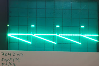
All frequency tests seemed ok, and the charge current tracked the frequency almost perfectly, charging the saw core capacitor to 5V even if frequencies changed. Only for the lowest frequency I tried (16.35Hz) did the cap not fully charge. I successfully tried frequencies up to 7000Hz. At 14000Hz the charge current was once again too low, but this was expected as the DAC output cannot reach a high enough level with the current combination of cap and charge current converter resistor (100kOhm). I tried swapping the resistor for a 56k one and the saw voltage swing doubled as expected, so a little experimenting with various resistor values will probably fix this issue.

I have had some issues with the saw core op amp oscillating. Not sure what causes it (well, I suspect it is due to the capacitor in the feedback loop), but some brands seem more susceptible to this than others.

I've tried the TL072CP and TL062CP from Texas Instruments and they both oscillate. TL072BD and 4556D from JRC work fine. Maybe the B/C difference could explain it.

The DCO uses modern, easily available components, the reset transistor is a 2N3906. The DAC currently used is a MAX541, with an SPI speed of 8MHz. The 'production version' will probably use a MAX5216 as this is way cheaper.

I was not aware that I could get such a high speed, now I consider moving the DAC update into the interrupt routine. It will probably double the time spent in the routine, but even this would only reduce the max transfer speed from the master controller to the DCO to around 950kbps, meaning we could still update the DCO 50.000 times per second (or rather, transfer new pitch values, the DCO will only update at period reset positions).

Next up is adding and testing SPI control, then recalculating the lookup tables to be centred around Cs (a C should be at 32768 = virtual 0V). Then finally breadboarding the wave shaper circuitry and deciding on voltage control and how to center the waves around 0V.

I must also decide the p-p voltage output. 12V seems to be the Juno way, this is the highest "safe" voltage possible since the saw is generated between gnd and the negative power rail (-15V). I assume that keeping the voltage as high as possible up to the point where several waves are summed is a good idea, to keep noise to a minimum.

The charge current is a bit too low at the lowest frequency


The dots above the peak of the saw wave is the reset pulse


The reset pulse gets more and more visible as the frequency increases and we zoom in

The charge current is too low above a certain frequency. This will be fixed.