Friday, December 4, 2020

Tons of new circuits ready!

So much has happened this summer and fall, and I haven't written about half of it! Some of it is directly related to the XM8, but most is utility circuits. I simply decided that I had to take time to do do some intermediate steps before building the final voice cards.

A shortlist of circuits I've designed, breadboarded, tested and finally produced at JLCPCB/DirtyPCBs follows below. Everything has been soldered by my good friend and colleague Stig-Rune!

Analog CV bank with 16 CVs in groups of 4.


For each CV you can select between lin or log/antilog  response, as well as uni or bipolar operation. Per group of four you can select the CV range, 0 to 2.5V, 5V or 10V (or +/-2.5V etc for bipolar). I did fuck up the PCB slightly so I had to cut a trace in three places and solder a wire. Also, I messed up a cable so I shorted the outputs, almost overheating the opamps. After that it worked perfectly. Output is via 10 minijacks and a 10p IDC connector for easy connection to a breadboard.


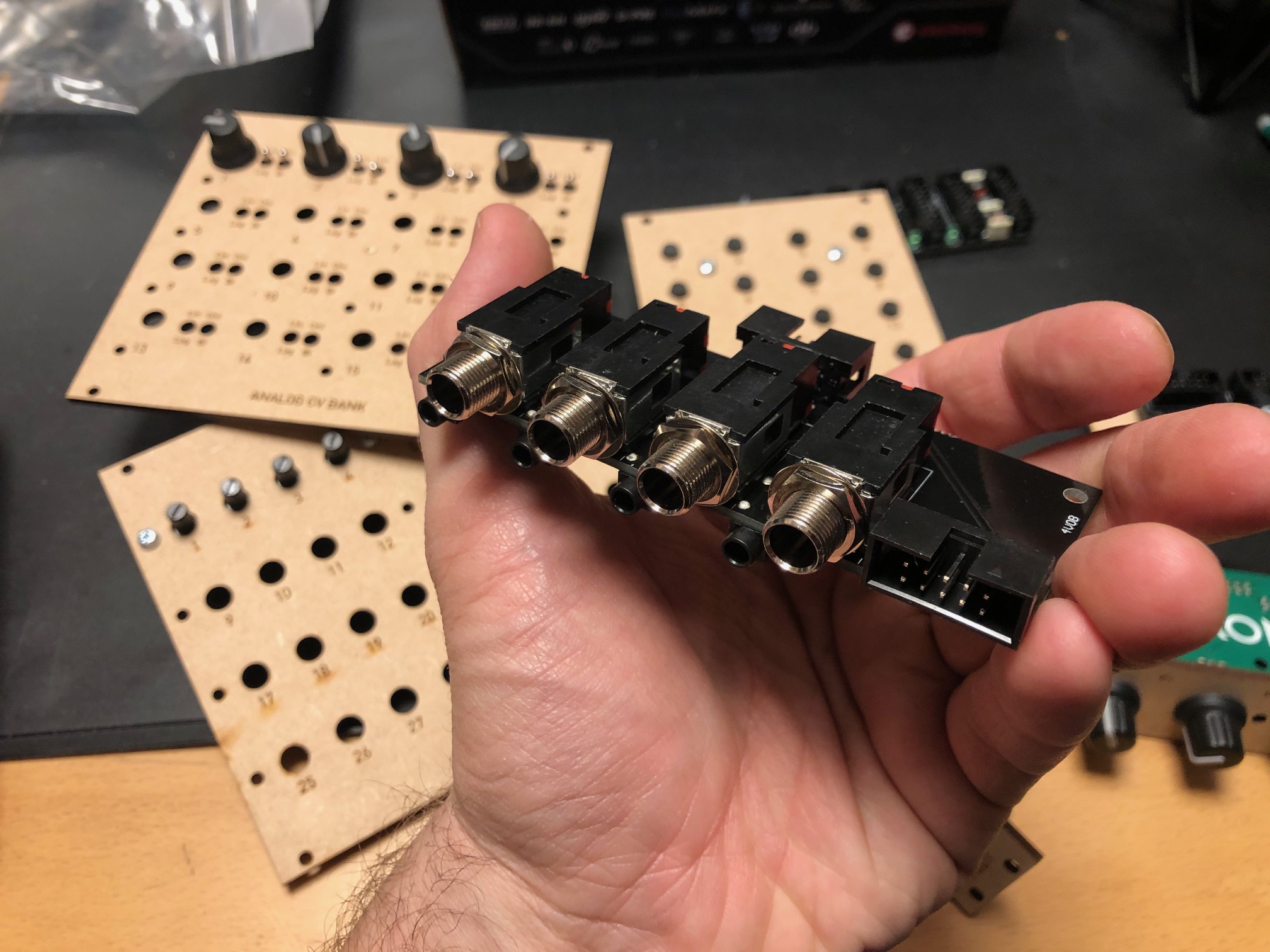
Quad input/output module with 1/4" jacks


For each module you can select input or output connected to the 1/4" jack, and the opposite will be connected to a minijack. Both ends are also connected to a 10p IDC connector for easy connection to a breadboard. For each channel there is an option of 10 or 2 x attenuation and 10 or 2 x gain, meaning you can either have a unity gain circuit, a 5x attenuation (for line out-ish) or 5x gain (for input).


24/48 button module, digital

A digitally scanned button module (without the microcontroller), chainable for up to 48 buttons. Serially read so it only requires four pins + power, making it possible to combine it with the potentiometer module on the same cable.


8 to 64 potentiometers module, digital


A digitally scanned potentiometer module (without the microcontroller). Each module has 8 potentiometers, and 8 modules may be chained for a total of 64 potentiometers. As with the button board, it only requires four pins, and it shares the same clock and reset pins at the button module so a total of six pins + power is needed for all digital modules. During testing I discovered that pin 9 on IC2 - one of the address lines - should have been connected to GND. Now it is floating, so it isn't possible to set the address correctly. It's an easy fix however.


4 x IDC Passthrough module

A simple panel with IDC connectors on both sides, makes it possible to route IDC connectors as a group through the front or back panel without putting the cable through a hole.


Bitcrusher

A combined 12 bit sample rate reducer and bit rate reducer with analog and digital control, based on a PIC16F18446 microcontroller with built-in ADC. Described in separate posts. I've ordered 25 of these.


20kHz LPF

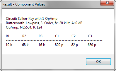
A filter module that can be used as an anti-aliasing filter for ADC input and reconstruction filter for DAC outputs. I use the same configuration in the Bitcrusher and intend to use this for the combined DCO/wavetable oscillators. The circuit comes from this page: https://www.analogfilters.com/anti-aliasing-filter/


Voltage Controlled Distortion

A distortion module for the XM8, the second of the two pre-filter FX (the bitcrusher being the other). Controllable distortion amount and output amplitude, as well as switch between hard and soft distortion. Untested.


Memory


A DIL mounted SMD chip, 128Mbit, for use as sample memory for the wavetable oscillators etc. Untested.


Prophet VS keyboard controller

A new revision of the 68b01 clone for the Prophet VS. I've ordered 20 of these so I have for future sales. They have all been programmed but are missing legs.


Modular synth power bus board

16p Doepfer standard boards with 7 connectors. A bit short but cheap to build.


10p and 16p breadboard IDC connectors

Tiny boards with an IDC connector on one side and legs on the other, making it easy to use ribbon cables between breadboards and modules


Unbuilt designs

In addition, I have PCBs for the following that has NOT been soldered yet:


Breadboard power and I/O module

Has input for +/-15v and a regulator for 5V. Also has IDC connectors for chaining multiple boards, and small chain-boards that can be fitted upside down to connect multiple boards. Connects to the power busses on the breadboard. No more risk of messing up polarities! Also: a 10p Doepfer compatible power connector, although the doepfer uses +/-12V, not 15V, and a 10p I/O connector that connects a ribbon cable to 10 pin headers for easy and stable connections. Pin 10 may be connected to ground with a jumper.


Breadboard coax connector and I/O module

A board with four coax connectors and the same 10p I/O connector as the board above. Will give stable connection points for oscilloscop, function generator and other gear that uses coax.


15-to-12v DC converter module

A module that converts +/-15v from either a molex connector or a 10p IDC connector to +/-12v and +5v. Output is through a 16p connector, compatible with the Doepfer standard. Also has a two pin header for injection of Gate and CV 


All in all 16 different boards! Needless to say, I'm more than pleased! I'm getting so close to being able to test an initial voice board, I just need to program some digital envelopes.


Bonus

I finally got the following soldered and ready for testing:

Two versions of the sample and hold buffer, one with some large caps and some filtering and one in a tiny DIL14 format, both quad sample & hold:


Then the second version of the DCO, this time with DAC output to make it a wavetable oscillator too:


Saturday, November 21, 2020

Bitcrusher tested

I got the bitcrusher from JLCPCB working today. Last week I discovered that some of the tiny 0402 resistors had lifted from their pads, so the input filter did not let the signal through. Last night my wife soldered them (I love her and how skilled she is, those parts are soooo small!), and today I was finally able to test everything.

The left pad of the two 0402 resistors have lifted. Not sure if this happened in production or when the pins were soldered.


I am still surprised at how recognisable the output is at 1 bit 27kHz. It has a lot of noise, but the music is still very audible. I am still not entirely convinced that it does not leak from the input, but when I reduce to 0 bits everything goes silent so I guess it is actually possible,

I had a lot of trouble getting the sample rate high enough, currently the max is at 27kHz with a 1:1 prescaler on timer 1 and a timer start value of 0xFEFF. Changing to 0xF0FF drops sample rate to 2kHz, so it's really sensitive. I need to work more on this but I am fairly confident that 44kHz should be possible.

I still want to confirm that the filters work as expected and have a 20kHz cutoff, but if that works as expected I think I'm ready to mass produce the filter. Perhaps just doing a quick input SPI check first.


Here is my test setup btw, for future reference.


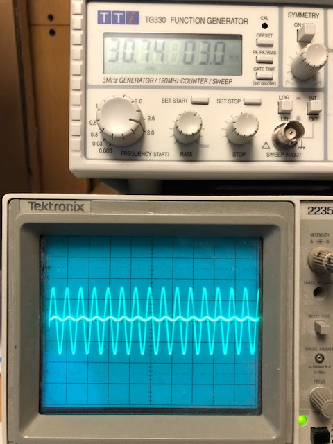
I've also tested the filter response for the input filter. It works fairly well although there are some slightly strange things going on. 

First of all, at 10-15kHz, the output signal (what the ADC sees) is amplified slightly, before it drops towards 20kHz. At 20kHz it is close to what I see in the simulation, so that's great. At 25kHhz it is even lower than what was simulated. There is also some distortion on the sine wave, not much but visible. I'm not too worried though, as this is not a hifi system. The tests sounded good enough to me. I'm more worried about the phase shift I see even at low frequencies, They may be very audible if the signal is mixed with the original. We'll just have to see (hear).

5kHz - no amplitude difference but a slight phase change

10kHz, the output has suddenly increased by 0.2V (5-10%)


At 20kHz we have a very visible attenuation. The filter is designet for 20kHz cutoff

Heavy attenuation at 30kHz


Friday, November 6, 2020

Shanpu switches

 I got a shipment of sample switches from Shanpu in Taipei today. I had to pay full DHL express freight but they were very nice and sent me the samples for free. I will be able to buy directly from them in multiples of 100 of each item, and the price ends up at around $1.4 per switch including cap, but shipping and a rather steep low-volume fee of $100 for orders below 1000 means the real cost is closer to $3-4 depending on the number of switches I buy.

There are several switches to choose from. All are rated at 1,000,000 cycles!

The SPH2S has an audible click and a short travel of 0.2 to 0.3mm, 190 +/- 50gf force

The SPH2T has a very audible click and a medium long travel of 0.4 to 0.6mm, 230 +/- 50gf

The SPH2N has a no audible click and a very long travel of 1.0 to 1.4mm, 60 +/- 40gf


Then there is a low profile version, but it is only rated for 100,000 cycles, so unless it is more suitable due to the low profile, I should really go for one of the others.

The SPFSP1 has an audible click and a short travel of 0.2 to 0.4mm, 200 +/- 50gf force


In some ways I like the N version best, it sits somewhere between the keyboard switch feel of the Nord keyboards and the normal clicky synth button. It doesn't feel quite right somehow though, it's like the travel is a bit too short or something.

The T is a bit too noisy for me, so that leaves me with the S. The click feel of the S is closest to the D50 when comparing to some of my synths. It is a little bit on the heavy side though, switching between it and the N makes me think I like the feel of the N better.


But then there is another issue - caps.

I ordered six different caps in four different designs

YCA085C, a 9.6mm round, transparent black cap with a "lense" effect on top. It turns out that it is glossy, and because of the way it has been made, with a hole in the center, the light is rather uneven. Not too much, but it is not the best.

YCA151A, same as YCA085C, but one mm shorter and Ice color (translucent white). The light is much better, but this may simply be because more light gets through due to the color, or it is because it is 1mm shorter. I have to retest the black one with a smaller diode. Of course, its white when switched off, so it will not blend into the design if I choose a black front panel.

YCA080C, an 8mm round transparent black cap. It has a more frosted look and is flat on top. It looks really great and the light is much better too. It has ONE major drawback though, and that is that it's only 3.3mm long. If I use a 3mm panel, or a long travel switch, it is simply too small for me. It's really a shame, because it's hands down the winner when it comes to looks. Oh, and it would be a perfect match for the 8mm black alu 

YCA059C, an oval transparent black. It is too small for my liking.

YCA044A, a square, 7.5mm ice white cap with a slightly rounded top. It looks good, but is too thin, and the led is clearly visible through, so I can't use it.

YCA043C, a square, 7.5mm transparent black cap with flat top. Unfortunately it is simply too transparent and completely useless. It WOULD however make a perfect base for glueing the black 8mm alu caps on top of, if I want to use them with the same switches. I may even use them for the red square Aliexpress caps.

Bonus test: The red square aliexpress caps look ok with the led, though they have an internal pattern that is very visible. It doesn't really look like they are meant to be backlit.

That means that I'm probably down to two options: The biggest round transparent black cap with whatever switch I like the best, or the 8mm round cap with the S-model switch and a thinner panel. I must test if I can get away with 2mm aluminum.


Update:

1 - There is an even better option for attaching aluminum caps: They sell a 5mm round cap, YCA052, which probably will fit very well inside the aluminum - perhaps with a 1mm gap that could possibly be filled with glue? There is also a 6mm one, YCA046. Perhaps I should buy both just to check. BTW: The top of the alu cap may be too thick for this option, but the extra cost of buying 100 caps is so little that it would be stupid not to do so.

2 - For the switches where the led will NOT be used, it would be possible to put a piece of black cardboard inside and coloring the edges of the cap holder black to get a much darker cap - the white parts shine through and making the insides black helped a lot.

3 - changing from a 270Ohm to a 150Ohm for the thicker transparent black cap helps. Still not as good as the other though, so I definitely have to test 2mm aluminum panels.

Tuesday, October 6, 2020

Nyquist and reconstruction filters in practice!

I assume you've heard about the Nyquist sampling theorem? It basically says that you have to sample a signal at twice the sample rate of the highest frequency you want to represent, that's why CDs have a sample rate of 44kHz - to be able to reproduce signals around 20kHz.

You may even have heard that doing so, you are not only able to reproduce an approximation of the original signal - you can reproduce an exact copy.

But have you actually seen this happen in practice? Let me show you! 


Sampling

A/D and D/A conversion is fairly simple in its basic form. Use an ADC and check the signal amplitude/level at set intervals. DAC is the reverse, set the amplitude of the output to whatever you got from the ADC (There is more to it than that for high quality signal reproduction, but for the sake of the discussion, and for the level of accuracy I need this suffices). 

Try this at home, looking at the output on an Oscilloscope and you'll quickly realise that the output looks nothing like the input. It has jagged edges, you can clearly see the height and length of the individual samples as output from the DAC. 

This is because there is one (two) more very important element(s) needed. To prevent aliasing - a higher frequency signal (outside of the audible frequency range) masquerading as a lower frequency one, we need to use a low pass filter before the ADC to remove frequencies that cannot properly be captured, e.g. frequencies above 1/2 of the sampling frequency.

When playing back the signal we need to do the same - as the DAC outputs a stepped signal it will generate lots of higher frequencies as well. By using a filter with the same cutoff - this time called a reconstruction filter - those are removed (once again, this is more complicated in practice for a high quality signal, but let's forget about that for a minute).


Ok, so that all sounds great on paper. Output a stepped signal and apply some magic, and you should get the original signal. But it can't be that easy, right?


Let's look at some photos:


DAC output (top) vs output after reconstruction filter

Here we see the output of a sampled sine wave (top) vs the output after the 20kHz reconstruction filter. It looks amazing! It works for other waveshapes as well of course, though if we were to zoom in on the edges of the triangle wave we would see that it's slightly rounded - this is because the frequencies required to reproduce it faithfully have been removed by the two filters. This is of course not a big deal as we wouldn't hear them anyway. 

Sampled and reconstructed triangle wave, tips are rounded by filtering.


The effect is even more pronounced with square waves which get a clear oscillation at the edges


Increasing the frequency of the input shows that the DAC output no longer resembles the input as closely - it has very few samples per cycle of the sine wave:


Now things start getting strange. Increasing the frequency even further "distorts" the DAC output even more. Remember, Nyquist says that it should be possible to reproduce a sine wave with only TWO samples per cycle. It sounds incredibly strange, but it actually works! Here is a 15kHz signal, filtered at 20kHz. The DAC output looks nothing like the sine wave it is supposed to represent:


Seeing this for the first time blew my mind. How is it even possible?! Well, read up on the theory behind it in Steven W. Smiths awesome book "The Scientist and Engineer's Guide to Digital Signal Processing" (available for free as separate pdfs from his web page) if you want the theory.


Effects of filtering


Now, there are some effects of filtering still present. First, we get some phase distortion, which increases as we approach the cutoff frequency of the filters. Looking at the input and output sines we can see that they don't line up properly:


As far as I know, this is not audible on its own. It WILL however be audible if the signal is mixed back with the original signal (which incidentally is how phasers are made). (PS: The photo is slightly misleading. Some of the apparent phase shift is only a delay between the input and output due to the time it takes for the DSP chain to process the signal. But the phase shift definitely increases as we approach the filter cutoff)

The second effect is that the amplitude (volume) of the output will decrease as we approach the filter cutoff. This is nothing special to this circuit, it's just how filters work - they do not have an absolute cutoff point, instead they gradually attenuate more and more. Having higher order filters with more stages will help - I'm using six poles in mine. High quality reconstruction filters however, do this differently. As we know how the filter affects the amplitude, we can do the reverse in advance - increase the volume of those frequencies. This cancels out the effect of the filter, keeping the volume constant for much longer. I have not bothered with this in my circuit as we're talking about fairly high frequencies anyway.

Saturday, September 26, 2020

Fake op amps?

I'm currently breadboarding the reconstruction/anti aliasing filter for the bitcrusher. Last night I noticed heavy distortion when the frequency approached 15kHz. Nothing helped, I even tried buffering the signal. 

Today I switched the TL072 op amps for 4558 opamps. And it worked straight away! I then swapped for some other TL072 with other numbers and it still worked.

I then tried using the original TL072s as simple buffers. When approaching 10kHz the sine input turned more and more to a saw wave. 

I popped in some other op amps I had laying around. LM1458 worked fine. Two versions of TL074 worked fine. But another batch of TL072 and one TL082, all with numbers fairly similar to the original TL072, failed in the same way.


Failing:

81SHC8M


At 20v p-p distortion is seen as early as 10kHz


Heavy distortion at 15kHz

Even worse at 20kHz

Reducing the amplitude to 14v p-p doesn't help


Working:

TL072 - 58CVY8M


Working fine at 20v p-p, 35kHz


I can only conclude that my stash of op amps has been infested by fake or faulty op amps. I tried googling the issue and found this:

https://sound-au.com/fake/counterfeit-p4.htm

https://forum.allaboutcircuits.com/threads/fake-tl082-are-actually-a-cheaper-model.141005/

https://www.muffwiggler.com/forum/viewtopic.php?t=179427

That site compares two TL072s - one with the number 18MDSHY which is assumed fake, and one 85AK87M, which is assumed original.

Funny thing, my *TL082* is numbered 18MDSHY... and the TL072s are 81SHC8M and 61SHC8M (My print is not bad in any way btw). My working TL072 is 58CVY8M and TL074s are 

LM1458 is WHY28M. It works fine at 20-30kHz but exhibits the same behaviour at 35kHz. That may be ok for an LM1458 though, I don't know.

Guess I'll have to dump my stash then :-(

Friday, September 25, 2020

Switches and caps again

 I've been trying hard to figure out a working combination of switches and key caps. I really don't want to use the normal tactile switches that so many old synths use. They wear out over time and the travel is very short.

Where I come from - IT - (and in the rest of the world I guess), mechanical keyboards are all the rage. Incidently, I used Cherry ML switched (and concidered Cherry MX) when I did the Machinebeats drum machine more than 10 years ago, long before Cherry MX became THE keyboard key. I even had a Cherry keyboard in the 90s. But I digress. What I'm saying is I want to use a proper switch, rated for millions of clicks.

The problem is keycaps. While Cherry do/did sell some non-keyboard keycaps, they are still square and keyboard-looking. That's why I want to create my own keycap. But 3D-printing the tiny mounts used for the various switches is not a very good option, especially with a filament based 3D-printer.

My idea is to use a commonly available keycap and mount MY part on top of that. That gives a much bigger surface to glue things to. However, getting a completely flat keycap seems almost impossible.

I'm considering four different switches: Cherry ML, Cherry MX low profile, Kailh Choc and Kailh Choc V2. The MX low profile seems really hard to find, but I've ordered the Kailh variants for testing.

After a few failed attempts, some nice, almost flat Kailh Choc caps arrived from Ali Express today. I immediately tried filing them down using some 180 grit sand paper. And voila! It looks great! The cap height went from 0.13" to 0.12", and now it's completely flat. Great Success! Only issue is the cap is ABS, so I can't laser cut the outline.


I'm still waiting for the switch. I've also ordered some round, flat-looking caps for the Choc V2, but it seems like I have a good option for the Choc so I might as well go with that.

On a separate note - using black keys was a really good idea, it is very easy to see when I have filed it down enough to be flat :-D

Sunday, August 30, 2020

DIY keycaps

 I'm trying to make some keycaps for the Cherry ML that are smaller than the standard square ones. My first try was mildly successful:


These were made using 0.8mm matte black acrylic. The text is engraved while the outline is cut. On the one with text, the hole has been cut as well, and we can see that it got too hot - the thin part below the hole is bent. 

On the second one, the hole has been made by engraving 6-7 times. This generates a lot less heat. Unfortunately, I chose to cut the outline afterwards, which made the thin part bend again. I think that cutting first, then engraving, would solve the problem.

I intend to mount the 0.8mm on top of a 3-4mm clear acrylic piece. It would also be worth trying to glue the pieces first to see if the cut gets better. I could then engrave the hole and stop once I reach the clear acrylic.

The text will be filled with white Lacquer-Stik.


I will glue the keycap on top of a fastening mechanism from other keycaps. The only issue is to get a good bond between the acrylic and the ABS which the keycap is probably made of. I've found a glue that promises ok results - Acri Bond 120.

Finally, I did the cutting with less powerful settings than our laser manual states.

3mm clear/black: speed 40, power 100

0.8mm black: speed 100, power 100

Saturday, August 22, 2020

VCO retesting and more detailed sync tests

 I retested the PW on my VCO and discovered that I had forgotten to ground two points. After fixing this, my own PWM works fine without pitch dropping.

I also did a more thorough test of various sync modes:


CEM Hard sync

- Datasheet says to sync against pulses, 1volt minimum, 3v maximum

In practice in my circuit

- Needs 1nF input cap

- Square wave with 50/50 duty cycle, +/-5v works fine.

- Saw wave, rising +/-5v works but only gives half sync

- Saw wave, falling +/-5v works but only gives the other half sync, and weird (but cool) behaviour when synced oscillator frequency is higher than master.

- Amplitude and offset of sync signal does not affect it.

- Strongly affected by PW, not in a good way


Conventional HS

- Datasheet says to use -negative pulses only, 8-10V

In practice in my circuit

- Saw wave, rising, +/-5v works. Falling does not work

- Square wave with 50/50 duty cycle, +/-5v works just like saw wave (but saw wave has a slight clip on top)

- Square wave with other duty cycle than 50% does not work well.    

- Not affected by offset

- Affected by amplitude, +/-5v works best

- Strongly affected by PW, not in a good way


CEM Soft sync

- Datasheet says to use negative pulses, max 5V

In practice in my circuit

- Needs 1nF input cap

- Square wave with 50/50 duty cycle, +/-5v works fine

- Saw wave, +/-5v, rising and falling works fine and sound the same, has a darker tone than square wave???

- Strongly affected by PW, not in a good way


Sync circuit conclusion

- I think I should build at least the prototype voice card with selectable saw, inverse saw or square wave input. 

- All waves should be +/-5v

- Waves should be tapped pre-VCA/mixer. Square should have its own square wave generator that is unaffected by PW and pulse VCA.

- I should give the option to switch between all three modes - to see how it sounds in practice

- I seem to remember that there was talk about constant frequency offset vs constant pitch offset in syncs, maybe worth investigating (but is a software issue, not hw).

Tuesday, August 18, 2020

LED ring update

 I got some work done on testing the LED ring with the MAX7221 7 segment encoder today, and the results are great. Both single led and multi led indicators are feasible and each has its own use. 

I tried with various lenses but my current conclusion is that no diffuser, red lense and a black panel definitely looks the best. Using a diffuser only made it look muddy.

The MAX7221 greatly simplifies the design/code. Multiple ICs can be chained, and I also think multiple parallel devices on the SPI bus are possible. One IC covers two pots with 32 leds.


I also got some amazingly good looking knobs today, matt aluminum, no indicator. Unfortunately, they have knurled, not D shaft, so it may be hard to find an endless potentiometer to fit it.

Tuesday, August 11, 2020

Great looking encoder knobs!

I've ordered a bunch of various knobs lately. I'm trying to find some that work with endless potentiometers/encoders, preferably D-shaft. It's harder than you'd think - most cheap knobs are for knurled/flower shafts, and almost all have some kind of groove or print to indicate position, which I guess almost everyone want.

It's really hard to tell from the photos on ebay and aliexpress etc if the knobs have an indicator, and sometimes they even try to hide it. Today I got the first delivery, and lo and behold - they look amazing! Just what I was looking for. Black spun  aluminum, D-shaft with no indicator! 


Here is the original description:


https://www.aliexpress.com/item/32924107059.html?spm=a2g0s.9042311.0.0.56d34c4dRi6Wum


Saturday, August 8, 2020

Breadboards - distance between power busses

 I am making some utility boards for breadboard power supplies and i/o. 

This means I have to know the exact dimensions of the breadboards. 

The senter piece is easy - holes are about 0.1" apart (though measuring the exact dims it seems that they are often a little off, just not enough to be a problem). In addition there are two holes missing in the middle. Distance between the two outer holes is then 1.1" or 27.94mm.

By looking at the cards I expected the same to be true for the distance between the columns and the horizontal "busses", after all, this would seem the reasonable thing to do. But this turned out to be a mistake! 

I did some googling, and found a site that showed a board that had the distance between the outer busses as 1.85" (the expected would be 1.9 if all holes were 2.54" apart).

I then made my cards to this standard, but when doing a test print, this turned out to be too little... The busses on MY breadboards at least are further apart. To make things worse, there are differences between cards that look similar but are from different vendors/orders ("luckily" there is also differences in the spacing of the tabs that connects the cards so cards from different batches cannot be connected properly - making it easy for me to know what cards are from what batch).

So, I have to take some accurate measurements to figure out what is going on.


Here are the dimensions of my two batches of boards:

A: Power busses: 9.40mm, main part: 35.45mm, total w/gaps: 54.58mm

- gaps are 0.17mm

- padding around busses is 3.43mm per side

- padding on main part is 3.76mm per side

- calculated distance between outer bus lanes is 47.74mm = 1.879 inches


B: Power busses: 9.45mm, main part: 35.5mm, total w/gaps:54.64mm

- gaps are 0.12mm

- padding around busses is 3.46mm per side

- padding on main part is 3.78mm per side

- calculated distance between outer bus lanes is 47.74mm = 1.879 inches


Wow, that was a bit surprising. Even though things looked very different, the inaccuracies evened out to make the end result equal for both batches. With the pretty lose tolerances in the making of these cards, I'd say that 1.88 inches is probably the distance to aim for. Measuring using digital callipers give a very similar result for both cards. 


As for the bus distances between cards with two and tree busses between them, they should be:

2 busses (four lanes) - distance between outermost lanes of each card: 

A: 2 * 3.43mm + 0.17mm = 7.03mm

B: 2 * 3.46mm + 0.12mm = 7.04mm

0.275 inches is 6.99mm, which is a good approximation

3 busses (six lanes) - distance between outermost lanes of each card:

A: 2*3.43mm + 0.17mm + 9.40mm = 16.43mm

A: 2*3.46mm + 0.12mm + 9.45mm = 16.49mm

0.65 inches is 16.51mm, which is a good approximation


Monday, July 27, 2020

FV-1 Multi-FX programmable reverb/chorus chip

I've been wondering for a long time what to do with the FX section of the XM8. I want something that isn't considered "cheap" or "tacky". I've scrolled passed the FV-1 at Banzai Music multiple times, but I thought that it seemed a bit limiting with its 8 built in programs, and it is also SMD which I try to avoid now that I'm unable to solder.

Today it popped up again when searching for "multi effects IC". I had a closer look and realised it is actually considered very good. There are open source effects available for it and it is programmable. The only limitation is that the programs have to reside on an EEPROM and that you can have only 8 of them.

BUT - the FV-1 accesses the EEPROM through I2C, which means that one can emulate the EEPROM using a MCU, and thus have full control over what it loads. That means we can do "in-circuit programming", or rather, have full flexibility and load as many progs as you want.

Here are a few links:

An article about the FV-1: https://reverb.com/news/fv-1-chip-history-5-pedals

Open source programs: https://github.com/mstratman/fv1-programs

Free programs from Spin Semiconductor: http://www.spinsemi.com/programs.php

A fully populated board, making testing easier for me: https://www.electro-smith.com/electro-boards/fv-1-dsp

Thursday, July 23, 2020

Quick thought on bitcrusher

The bitcrusher works in two ways - it reduces sample rate and it reduces the bit resolution.

A good quality audio DAC circuit needs a reconstruction filter after the DAC to remove unwanted high frequencies ( >20kHz). When sample rate is reduced, this filter's cutoff must also be reduced to approx twice the sampling rate to keep the quality.

BUT - in a bitcrusher, don't we actually WANT the coarseness caused by not filtering the signal perfectly? I assume so. This has to be tested.

I will try building a bitcrusher with a simple ADC->MCU->DAC->static LPF and see. 

https://en.wikipedia.org/wiki/Bitcrusher

PCM player, DAC, PIC32MX and I2S

I have multiple options for a wave player/sampled attack/wavetable oscillator.

- I can add a DAC to the Voice controller and control it directly there - using a I2S Audio DAC will probably give a very high audio quality

- I can make a separate board with the same DAC, an extra MCU and external memory

- I can try to use the DCOs - they already have a 16bit DAC and I think I have exposed enough SPI pins to make it possible to access external SPI memory. This is the cheapest option but the sound quality must be tested.

In any case, when making the Voice board I should leave room for an optional wave card. It doesn't need its own VCA as the DAC should be good enough for volume control as well.


PIC32 and I2S Dac

It seems most Audio DACs these days use I2S for communicating with the host. The PIC32MX (and other low-end PIC MCUs) don't have I2S support built in, but here is something that seems to make it work:

https://www.aidanmocke.com/blog/2018/11/22/i2s/

https://hackaday.io/project/28965-pic32mx-music-box-with-fm-synthesis-and-i2s-dac

https://tutorial.cytron.io/2017/08/13/i2s-pic32mxmz-introduction/


DAC in general

DACs need a reconstruction filter to remove unwanted frequencies. Here is an example that claims to be good:

https://www.analogfilters.com/high-quality-reconstruction-lowpass-filter-for-digital-audio/

Circuit

Components

https://www.softwaredidaktik.de/active-filters/download/

Sunday, July 19, 2020

Oscillator UI

Just an initial sketch, let user morph between waveforms, and select what waveforms should be included in the morph:

By selecting only certain waveforms for morphing means one can start a morph by a modulation source at a different point than sine.

How to select various stuff for modulation by various sources needs to be investigated.

Friday, July 17, 2020

Distortion circuit mostly ready for production

I've finished v1 of the distortion circuit PCB:


I still have to double check the schematics, I've done so many silly errors lately...

The board has switchable soft/hard clipping, and CV adjustable distortion and output gain.


Little/slim phatty distortion/overload

Before I send this one to production, I will breadboard and try out the distortion circuit from the little phatty:


It looks fairly similar, but the output, labeled audio_sum, is actually connected to a point BEFORE the input, labeled mixer_out here. This means it actually feeds the result back to the start, not only distorting it (there is only buffer and voltage divider between though). Also, the overload_cv controls an additional output VCA located after the filter. I can't tell from the circuit diagram what the gain / level is at various points of the circuit so I will simulate this.


Wednesday, July 8, 2020

VCO testing

I've tested my CEM3340 VCO with waveshaper. It works fairly well. It has one major flaw:

Triangle frequency drops when changing pw from 50/50 to 90/10. This was expected for the Cem PWM, but it happens, and is even more pronounced, with my own pwm! I have tried buffering the supply lines (+/-15v) but it doesn't help

In general it is extremely sensitive to voltage changes, so my breadboard isn't exactly the ideal test platform. But it is annoying none the less.

Other than that:

  • All waveforms work fine
  • Linear FM works fine
  • Hard sync works fine
  • Cem Hard Sync works fine, but only with a 1nF cap in series with the input signal. Normal hard sync works without this (prob. because it already has a 220pF series cap) but also works WITH.


Saw wave, CEM Hard sync

Saw wave, normal hard sync

Saw wave, CEM Soft sync? Doesn't seem to work very well, not sure how it is supposed to work really (noone seems to know :-D)

Triangle wave, CEM Hard sync


Triangle wave, normal hard sync


Triangle wave, CEM Soft sync. Again, it looks like CEM hard sync. Not sure what to expect.


Friday, July 3, 2020

Ring modulator tested, seems to be working

I tested my version of the yusynth.net ring modulator today.

I tried connecting VCAs on the inputs but it doesn't seem very necessary, they affect the signal almost exactly like the output VCA does, so a single output vca will do fine.

1uF input caps seem like a good idea, perhaps an output cap too

I used a 500R pot in place of a 200, looks like I got away with it.

Trimming is done as described in the picture (same as on yusynth.net):


Thursday, July 2, 2020

JP6 Filter - error on PCB

I have managed to mess things up with the JP6 filter as well. I've drawn one single trace using layer 97 - info instead of the trace, so the left base of the cutoff CV expo converter is not connected to GND.

This is possibly the single worst place on the whole board to err, as the transistor IC is soooo tiny:


Update 7th of July: I found a second error, R22 should be connected to the negative mixing point of the resonance OTA (IC4A), not the junction between R19 and R19 (pin 1 of IC2A).

After fixing this, and realising I had used a 100k instead of a 10k resistor between the VCA CV and the mixing point (resulting in a +/-0.5V swing instead of +/-5V), everything works beautifully.

However, the output of the first cell has a swing of +/-5V when +/-6V is expected. This can be fixed by increasing the output gain, but it means that the 100k pot on the output op amp is maxed out. One needs to increase the value to have room for adjustment (adding a 22k series resistor probably fixes it). Not sure why the cell output is too low, this must be investicaged further

Update 8th of July: I found a third error... The output is fed back into the wrong pin on the overdrive OTA, meaning it attenuates instead of overdriving the signal. I also forgot about a resistor on pin 15.

In a new revision I should also consider again if the overdrive should happen pre-output VCA, now it is not possible to keep volume the same when overdriving, output is almost doubled when max overdrive is turned on.