Showing posts with label op amp. Show all posts

Saturday, May 11, 2024

Clip detection

I want to detect when the signal on the mix bus is about to clip, to be able to indicate it in the UI.

I initially intended to use the Elliot Sound Products clip detection circuit to do bipolar detection:

There are a few issues with this though. First of all, the output after the diodes is 0-10V, which is too high to be used directly with the mcu inputs.

 Second, as I will not interface this directly with the mcu, but rather with the PCA9539 port expander, it won't trigger an interrupt. Instead, I have to poll the signal - so I need to latch the state whenever a clipping pulse is received, and reset state after I've read it.

It is possible to make an SR-latch using an op amp, as described here https://www.radiolocman.com/shem/schematics.html?di=463517 and here https://www.edn.com/use-an-op-amp-as-a-set-reset-flip-flop/


 After a bit of fiddling with my simulation, I was able to come up with this circuit:

The output of the comparator op amps is +/- 10.4 approx. This is dropped to around 0-9.8 through the diodes. R3 and R4 divides the signal down to around 3.3V. It is then buffered, and inserted into the latch through the diode (dropping an additional 0.6V). R15 and R16 sets the value seen at the negative pole of the last op amp when in2 (reset signal) is turned off. R14 adjusts the reset voltage so we're able to reset the latch, and D3, R17 and R18 reduces the output from +/-10.4V to 0-3v3, ready for the MCU.

After even more fiddling, trying to reduce the number of components, I ended up with this:


It works just as well as the previous one.

Green: input at positive terminal of the right op amp. Blue: Reset signal. Red: latch output


Now, I did a lot of testing with this circuit and it has one big issue. At frequencies of around 5kHz (with a triangle input) the comparators are too slow, so the peaks are not high or long enough to properly set the latch. As we get closer to 20kHz it simply stops working. If I lower the detection voltage (replace the 1k resistors with 2k2 for example), it works, but the clipping voltage level changes with frequency. That's not very good - though it may be GOOD ENOUGH.


Enter V2.

Let's do this the proper way.

By replacing the op amps with LM311 comparators, and the op amp-based latch with a real latch, CD4043, things work fine all the way up to 20kHz+:

The 10pF caps are not necessary, and the 10k/100k/10k voltage divider at the input can be replaced with 1k/10k/1k.

The CD4043 is driven from a 3v3/GND PSU, so level shifting is not necessary.


An imporant thing to note here is that the top comparator has the collector (pin 7) connected to 3v3 and the emitter (pin 1) connected to GND through a 10k resistor. In this configuration, the output (connected to pin 1) will be high whenever the voltage at the negative input (3) - our signal - is higher than the voltage we compare against (2, 10V), and the voltage range is 0 to 2.7 approx. CMOS inputs are considered ON when the voltage is > 2V (for 3v3 supplies) so this is fine.

For the bottom comparator, the collector is connected to 3v3 through a 10k resistor and the emitter is grounded. The output (connected to pin 7 this time) is positive whenever the voltage at the negative input (3) - our signal - is lower than the voltage we compare against (2, -10V).

As the signals are fed into different latches (there are four available in one CD4043), we actually have separate clipping indicators that we could read if we wanted to. This is not necessary for my use, so I simply combine them using two diodes (again, dropping the voltage, but it still works with the PCA9539).

Positive clipping only

Negative clipping only


Some action shots

White = reset signal
Brown = clipping state, as seen by microcontroller
Orange = output from CD4043 comparator (v2)
Red = output from LM311 comparator for high clipping
Blue = output from op amp latch (v1)
Yellow = input signal from function generator

4.8Hz input, says 19.5Vpp on function generator (fg) but is about 20Vpp measured. Both versions trigger

48Hz, 19.4Vpp on fg. Both versions trigger

517Hz, 19.4Vpp on fg. Only v2 triggers.

517Hz, 19.5Vpp on fg. Both versions trigger again.

5kHz, 19.4Vpp on fg. Vmax is > 10V so both should trigger. Only v2 triggers

5kHz. We have to go all the way to 20.1Vpp on the fg to get v1 to trigger


10kHz, have to increase to 20.5Vpp on fg to get v1 to trigger

20kHz, v1 doesn't trigger even at 20.9Vpp on fg


Thursday, February 9, 2023

Distortion 1.3 (?)

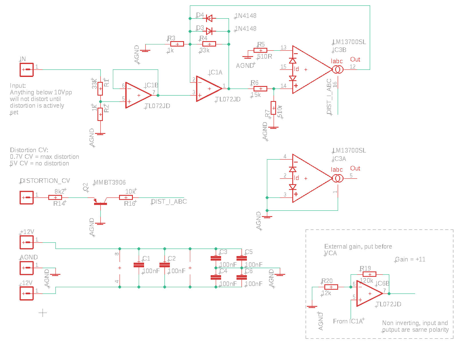
So after all the distortion testing, I've landed on a very simplified circuit:


This one only does soft clipping, but with a very reduced parts count compared to the soft/hard one.
It has no VCA and no switching, and CV control is simplified (which means that the upper 0.7V of the CV is not effective due to the voltage drop across the transistor, but it saves an op amp.

I had hoped that I could connect the output of IC1A directly to the VCA through a < 4.7k resistor, to make the VCA into a gain stage, but that introduced too much non-linearity into the equation. We need to use the non-inverting amplifier in the lower right corner, but it can be placed externally to save space on the distortion board. If we choose to have it on the board we should also reintroduce the CV circuit from the previous distortion to make cv 0-5V again.

Bottom: Output of VCA shows that the almost linear triangle input has been distorted. This is when connecting the output of IC1A directly to the VCA through a 3k3 resistor.

When using an op amp gain stage in between, most of the non-linearity is gone. What is left is introduced by the distortion circuit, see the output above.


Sunday, February 5, 2023

High frequency filtering in audio output

One thing that I've put off for a long time is selecting filter caps for various op amp output drivers. 

Today I had a look at some datasheets to figure out what others are doing. 

Generally, it seems that filtering (by putting a cap in parallell with the feedback resistor in an inverting op amp) is only done at the last stage of the circuit, not within the circuit itself. It seems that very little filtering is done except for biasing using electrolytics in the audio path to center the signal. I assume the final filtering is just to stop radio frequencies, stuff that we don't want to escape the circuit perhaps?

Here is what I found

Self on audio (book) page 237: 100pF/4k7 = 339kHz

Self on audio (book) page 359: 27pF/10k = 589kHz

JP8 source mix: 10p/100k = 159kHz

JP8 VCA cont 15p/100k = 106kHz

Juno 6 out: 47p/3k3 = 1.02MHz - See juno 60 where the 3k3 is actually crossed out in the schematics and 27k written instead.

Juno 60 out: 47p/27k = 125kHz

Juno 106 out: 22p/33k = 219kHz - Interestingly enough, and supporting of my theory that filtering only happens at the last stage, the 106 has the same feedback resistor as the Juno 6 (3k3) right after the filter, but no cap, as it has a mixer at a later stage too, mixing in High-pass filter.

JX-3P out: 330p/10k = 48kHz

JX-8P synth mix: 100p/47k = 33.8kHz

JX-8P chorus: 100p/22k = 72kHz

THAT4301 reference: 47p/20k = 169kHz

Sooo, I can't say that the findings are exactly conclusive. Before starting this research I suspected that the cutoff would at very least be above 22kHz (being the upper limit of human hearing) and perhaps at least the double as we want to make sure to not remove anything wanted. Most of these results seem to support that, with roland ranging from 33kHz up to 219kHz (disregarding the Juno 6 which seems to be too high). I'd say somewhere between 100 and 150kHz is probably a nice compromise.

Now, I started looking at this to find a good cap for my distortion circuit, which has an output feedback resistor of 120k. Playing around with various caps and looking at the output of the scope, it seemed like 10p would give a result where frequencies up to 22kHz did not get much attenuated. Calculating the cutoff using 120k/10p gives 133kHz which incidentally fits nicely between 100k and 150k.

That said, as the distortion is in the middle of the circuit, I may as well skip filtering alltogether.

Monday, January 30, 2023

Changing center and range of a signal

I needed to change a +/-12V input to 0-3.3V. This calculator has the solution in the form of a differential op amp calculator:

https://masteringelectronicsdesign.com/differential-amplifier-calculator-2/

PS: You may have to use a negative reference voltage.

Saturday, September 26, 2020

Fake op amps?

I'm currently breadboarding the reconstruction/anti aliasing filter for the bitcrusher. Last night I noticed heavy distortion when the frequency approached 15kHz. Nothing helped, I even tried buffering the signal. 

Today I switched the TL072 op amps for 4558 opamps. And it worked straight away! I then swapped for some other TL072 with other numbers and it still worked.

I then tried using the original TL072s as simple buffers. When approaching 10kHz the sine input turned more and more to a saw wave. 

I popped in some other op amps I had laying around. LM1458 worked fine. Two versions of TL074 worked fine. But another batch of TL072 and one TL082, all with numbers fairly similar to the original TL072, failed in the same way.


Failing:

81SHC8M


At 20v p-p distortion is seen as early as 10kHz


Heavy distortion at 15kHz

Even worse at 20kHz

Reducing the amplitude to 14v p-p doesn't help


Working:

TL072 - 58CVY8M


Working fine at 20v p-p, 35kHz


I can only conclude that my stash of op amps has been infested by fake or faulty op amps. I tried googling the issue and found this:

https://sound-au.com/fake/counterfeit-p4.htm

https://forum.allaboutcircuits.com/threads/fake-tl082-are-actually-a-cheaper-model.141005/

https://www.muffwiggler.com/forum/viewtopic.php?t=179427

That site compares two TL072s - one with the number 18MDSHY which is assumed fake, and one 85AK87M, which is assumed original.

Funny thing, my *TL082* is numbered 18MDSHY... and the TL072s are 81SHC8M and 61SHC8M (My print is not bad in any way btw). My working TL072 is 58CVY8M and TL074s are 

LM1458 is WHY28M. It works fine at 20-30kHz but exhibits the same behaviour at 35kHz. That may be ok for an LM1458 though, I don't know.

Guess I'll have to dump my stash then :-(

Sunday, January 27, 2019

Jupiter 6 filter - oscillation issue

I did a lot more work on the Jupiter 6 filter today.

First of all, I tried figuring out why I get oscillation on the input whenever cutoff CV was above 4.7V.

I have yet to figure out what is going on, but I tried replacing all ideal opamps with TL072 simulations and I still have the issue. I will have to breadboard the circuit to see if it is real or not.

But even so, there are a few things that make this happen:

1) When resonance CV is at 0V, I get oscillation if cutoff CV > 4.7 and input gain feedback resistor > 3.9k. With 4.7V CV I could use at least a 15k resistor without problems.

2) Decreasing the 33k resistor from input to the resonance OTA, or removing the line completely, fixes the problem

3) Increasing resonance also removes the issue.

All in all, it seems that anything that makes MORE current pass through the circuit causes this oscillation. I tried quickly reading up on op amp oscillation but no quick remedy was found. I also cut down on the circuit to the point where only the first SVF with constant current controls (no expo converters etc) and no output VCA was left and still had the issue.

Friday, August 4, 2017

DCO: Culprit found but not fixed

I did extensive testing of various op amps yesterday, and as suspected, the amplitude error at low frequencies is caused by the op amp. I also tried recalibrating the power supply but that had no effect whatsoever.

The results from various opamps varied wildly, and results from positive and inverting buffering configs also varied a lot.

My best hit was with a UA741, in inverting mode the amplitude was perfect across the entire frequency range! Unfortunately, it was only a lucky strike, I retried several other UA741s and the result varied from around 7 to around 13V amplitude (when the real amplitude should be 10V).

The conclusion then is that at voltages very close to zero will experience a lot of variation even between specimens of the same family.

Tested op amps

UA741 variations

I am not sure how the effects are over time and temperature, this must be tested.

If  the effects are mostly production variations, it would be possible to calibrate each DCO.

This can be done in code even if DAC lookup tables must reside in program memory due to RAM limitations (1kB of memory is required for DAC keystep and rise-per-substep tables and the MCU only has 1kB of RAM in total). The PIC16F allows programmatical/runtime writes to flash program memory, and though there is a limit to the number of times this can be done (>10 000), even a write on every system startup would probably be possible.

Hopefully though, calibration will seldom be necessary. As a nice side effect, calibration will correct variances in both charging caps and resistors as well as opamps.

Calibration

Here is how I imagine it to be done:

A reference voltage is applied to one of the MCU pins. This is used as the reference voltage of one of the internal comparators.

First, apply the lowest frequency. By increasing and lowering the DAC output voltage until the comparator changes polarity, we figure out
- if the voltage is too high or too low
- if the amplitude error is within acceptable limits

A slightly too low amplitude is acceptable but a too high amplitude is not as this will trigger the comparator during normal operations, if we choose to use it as a reset-on-frequency-change trigger. The amplitude must also be adjusted to always be slightly lower than the comparator trigger point to prevent false triggers.

We also have to consider measuring the highest frequency amplitude error to see if errors are always either high or low. For now, I'll assume that they are always one or the other.

After finding the initial error, one loops through the remaining 255 samples, starting from the bottom.

For every frequency, the DAC voltage is increased or lowered (based on what we found for the lowest frequency) until the comparator changes polarity - this gives us the "correct" value for that step. To save time, we may stop checking once we reach a frequency where the error is small enough (and lower than the comparator voltage).

We should now have a correct lookup table for key samples. All that is needed now is to calculate the interpolation lookup table, and write everything to non-volatile flash memory.

To minimise the number of recalibrations, we could let the DCO check the keysamples on startup. If they are still within limits, no recalibration is necessary.


A different approach to finding the current amplitude would be letting the DCO control a PWM-based DAC to generate the reference voltage. It could then change the reference voltage instead of DAC output value to find the amplitude. Not sure that it's a better approach though.

PS:  If the signal amplitude is 10V, using a resistor divider with R1 = 100k and R2 = 68k will get the amplitude down to 4.048V. This lets us use the internal 4.096V voltage reference with the comparator.

Thursday, February 23, 2017

TL0x2 opamps - difference

- TL062 is the low power version of the TL082. 
- TL072 is the low noise version of the TL082. 

So: the TL062 uses less power, but is more noisy than the TL072.


From: http://www.freestompboxes.org/viewtopic.php?f=17&t=328