Showing posts with label errors. Show all posts

Thursday, July 6, 2023

JP6 filter oscillations and latch-up

I've had serious troubles with the JP6 filter since I started working on it again about a week ago.

- it latched up whenever the cutoff CV was > 1.5V
- it had severe high-frequency oscillations

Today, I finally got it working again (with the Jove CV generation circuits). Here are the three things I fixed:

- Cutoff and Resonance Iabc has to go to two cells, not only one (or they will be too large)
- I had messed up and used a 3pF instead of a 330pF cap
- And even after fixing that, I realised that the caps were probably not in contact with the connectors. I redid the wiring there and everything started working.

Back to the real testing!

Tuesday, January 10, 2023

DCO Calibration issue

After fixing the issues with calibration related to the compiler bug, I hoped everything would go smoothly. Unfortunately that was not the case.

After calibration, when running through frequencies, I would sometime see a kind of discontinuity, where the wave amplitude would drop to zero and then build back up to the correct height again over two periods. 

I looked at the DAC charging voltage and could see a kind of asymptotic behaviour where the charge voltage suddenly rose much faster than it should, and when it reached max, dropping back to zero but still rising with the same speed. Clearly the DAC output overflowed.

DAC Voltage error. The first little drop is only due to missing calibration. The asymptotic looking one is where the interpolation overflows and voltage drops to 0.


It took some testing to figure out what was going on: For a single sample in the calibration, the dac voltage was detected significantly lower than it should, and more importantly, lower than the previous sample. This meant that the slope multiplier should have been negative. But the slope multiplier is unsigned, so it overflowed and ended up with a large positive number instead.

Then, when interpolating between the two values, we would add a large number instead of subtracting, leading to the spike (and DAC overflow) we saw.

But why did we get the wrong value during calibration?

It happens during the first cycle of a single note calibration. For some reason, we detect that the wave amplitude is too high - higher than the comparator voltage - when in reality it is not. This leads to the binary search continuing in the wrong half of the voltage range and the calibrated voltage ends up being around 32768 instead of what it should have been.

DAC voltage calibration - 7th cycle starts off too low and never reaches back up to the correct voltage.


Debugging the issue is a pain in the ass, because we are dependent of the wave being reset at exactly the same point every time. If something changes, the voltage may not cross the comparator voltage, and while it seems we have fixed the error, it still might be there.

I strongly suspect that what happens is that the voltage reaches the comparator voltage AFTER we have changed the dac and timer to a new frequency, but before the interrupt handler resets the wave. My fix was to move clearing of the comparator flag into the interrupt routine, so we are guaranteed that a comparator interrupt stems from the current cycle, NOT anything before it. It looks like it works but who knows...

I also saw another strange thing - some of the cycles are of different lengths than they should be, by as much as +2us. But then, often the next cycle or the one after that is a bit shorter. I have not been able to properly explain what is going on. I suspected that the comparator interrupt may have been part of it, that it triggering would make the program enter the interrupt routine before the timer interrupt, and then staying there for long enough to delay the timer interrupt, but I have not been able to confirm this. My fix was to disable comparator interrupts once we get it once during the calibration period, to prevent the code from reentering the interrupt routine due to the comparator interrupt being high. When this was NOT done, we would probably enter the interrupt routine repeatedly until the timer interrupt fired and disabled the comparator.

Now everything seems to work properly and I've started working on a verify routine, one that runs through frequencies where I suspect the charge voltage may be too high (such as in the middle of interpolation) and checking if we hit the comparator voltage during normal operation.

Low range sweep after calibration

High range sweep after calibration


I do however suspect that that is not the case. Had the timer been exponential between two key points and the voltage linear we would see an error, but both are linearly interpolated meaning the voltage should match the frequency fairly well. 

We have another error too - a strange falloff at the end. The charging voltage is too low even if the DAC has not maxed out. The consequence is rather low as this is in the > 20kHz range but I still want to figure out what is going on.


Thursday, March 31, 2022

Saving the DCOs

I've posted about this before, but I did a crucial mistake in rev 1.4 of the DCOs. Unfortunately, I also ordered a full set of them (40x) and the microcontroller and DAC (DAC8830) I used have since become unavailable at JLCPCB, so I can't just order a replacement.

My mistake was that I reduced the resistor the DAC outputs through from 100k to 22k, thinking that it had to be less than 60k when in reality it should be MORE THAN 60k.
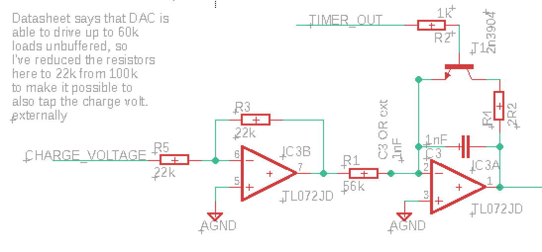
I need to replace R5 with a 60k resistor

Fixing this means desoldering at least one resistor, but after that I have some options.

The "correct fix"

The correct fix would be desoldering R3 and R5 and replace them with new 60k resistors. It is a bit finicky to do this, especially removing R3 will be hard. (UPDATE: Even this would not make the output perfect, see Update 3 below)

Easier fixes (?)

The DAC feeds into an inverting op amp with unity gain (Rf = Rin = 22k). 

By replacing only Rin with a 60k resistor, I would get an inverting amplifier that attenuates the signal to -Rf/Rin = -22k/60k = -0.37.

Unfortunately, attenuating inverting amps are known to self oscillate. The solution, as described here and here, is to put a resistor of the same value as Rf from the negative input to ground. 

There are a few ways to add this resistor. 

First, I may add it directly between leg 5 and 6 on IC3. It may be possible to use a 0603 resistor, or at least a 0402 directly, but it may be a bit hard.

IC3 pins 5 and 6 are in the lower right corner


Second, I may desolder R5 and put a tiny wire from the top pad to pin U1 (utility 1). Doing things that way means I could add a replacement for R5, as well as a resistor to ground, on the board the DCO plugs into. 

Charge current

Since the output from the inverting op amp now is much smaller, I also need to place a resistor in parallel with R1 to increase the capacitor charging current. I need to do this anyway, as the DAC output in my original design was 5V, but running the DCO from 3.3V means the DAC output now can never reach above 3.3V. 

Another option would be to simply amplify the DCO output. I do this right now on my prototype, I need to do some calculations and experimentation here to see what is the best solution.

Change nothing

The last option I have is to do a bit of measuring on the DAC output. When do we run into problems? Is the max 60kOhm load rule for the whole range or just for the higher values? Is it related to the output current?

If it is indeed current related, we may have a few options. First of all, maybe reducing the reference voltage, which in turn reduces the output current at max, is enough? 

Similarly, if the higher values are the issue, could I get away with using only 15 bits, leaving the MSB at 0? Testing is needed!

Update 1:

Measurements from the DCO


This is weird. I did a lot of measurements and calculations. The DAC voltages follows the pitch, no errors as we go up the scale (apart from some tiny errors at the bottom that may as well be with my probes).

However, I have connected 3.3V as Vref. According to my calculations this means the output voltages are off by 25%. BUT - when I replace Vref with 2.5V in my spreadsheet, I get exactly the output I see on the dac! The error is around 0.5%, and that's to be expected since I haven't included the slope part of the lookup. This is SO weird. I need to look at this again tomorrow.

Update 2:


Changing to a 2.5v reference made the max value drop from 2.17 to 1.66V (Expected is 2.84 and 2..16 respectively). The diff is still 23% and it is still consistent across the DAC range.

Next up: breadboard a new circuit and check if the output changes (and at what rate) when changing the resistor.

PS: the DAC output impedance is approximately 6.25 kΩ

Update 3:

I did some measuring during my lunch break, and the results are extremely uplifting:

I replaced the input resistor Rin and measured the DAC output for various values. Then my hunch told me to compare it to what would happen if we measured the mid point of a resistor divider between Vref and GND, where the top resistor is equal to the DAC output impedance (6.25k) and the bottom resistor is equal to Rin. 

The two voltage columns speak for themselves - it is clear that this is what is going on. This means that
- The output will probably be exactly the same between the various DACs I'm using
- Even if I changed to a 60k resistor, I would not get a perfect result

In other words, I can probably just leave the 22k Rin as it is, and compensate in the charging resistor part instead! This is just amazing!

Even better, I added a buffer after the DAC, to see if tapping the output for my wave player idea affects the output, and it absolutely doesn't :)

Update 4:

I tested connecting a resistor in parallel with R1 to increase the charging current. Originally I intended the max charging current to be 5V / 56kΩ = 89.3uA. Now the max DAC output is 1.94V if we use a 2.5V reference, so we need R1 to conform to 1.94V / R1 = 89.3uA, meaning R1 has to be 21725Ω. By putting a resistor in parallel with the current R1 we can lower the combined resistance - to get a combined resistance of 21.7kΩ the second resistor needs to be 35.5kΩ. If we choose a 36kΩ resistor, the combined resistance is 21.9kΩ and the current 88.6uA, fairly close to the ideal.

I tested this, and the wave amplitude instantly jumped to 9.4V (With a 3.3V reference, it passes 10V. The tops are cut off but I assume that is because the calibration output (connected to the microcontroller) is > 3.3V, I've seen this happen before).

So - all I have to do to make the DCOs work properly - with a 2.5V reference instead of 3.3V btw - is connecting a 36kΩ resistor in parallel with R1, and 75kΩ and 3.3kΩ resistors (in series, so 78.3k) in parallel with R7 to get the correct value at the MCU calibration pin - see https://atosynth.blogspot.com/2022/01/big-bug-weekend.html for calculations of R7


Increasing max frequency


Right now, the DCO has a range of 8Hz to 8kHz. I want to move this to 16Hz-16kHz (or 20Hz-20kHz).

This can be done either by decreasing C3 from 1nF to 500pF (560pF may be the closest option), or by changing the value of the resistor in parallel with R1:

We now need the max charging current to be 178.6uA, meaning R1 should be 10.86kΩ. The necessary parallel resistor would be 13.4kΩ. It is better to choose a slightly lower value than a too high one, so 12k may be the best standard value.

Update 5:

By swapping R1 with a combined resistance of 14.5kΩ and using a Vref of 2.5V I'm able to cover the full midi range (8Hz to 13.3kHz) with only 3 cent errors on the highest pitches. This does not leave room for pitch bend at top/bottom, but each note is exactly 512 steps up from the previous which is a nice number to work with in the voice controller.

Reducing to 9.1kΩ lets us add another 12 semitones, giving us a range of 5Hz to 21kHz, though I'm not sure it's worth it.

All in all, I think I should consider making a bootloader for the DCOs, there are so many things that could be changed after install, and having to manually change 16 (or 32!) of them would be a real pain.

Friday, August 4, 2017

DCO: Culprit found but not fixed

I did extensive testing of various op amps yesterday, and as suspected, the amplitude error at low frequencies is caused by the op amp. I also tried recalibrating the power supply but that had no effect whatsoever.

The results from various opamps varied wildly, and results from positive and inverting buffering configs also varied a lot.

My best hit was with a UA741, in inverting mode the amplitude was perfect across the entire frequency range! Unfortunately, it was only a lucky strike, I retried several other UA741s and the result varied from around 7 to around 13V amplitude (when the real amplitude should be 10V).

The conclusion then is that at voltages very close to zero will experience a lot of variation even between specimens of the same family.

Tested op amps

UA741 variations

I am not sure how the effects are over time and temperature, this must be tested.

If  the effects are mostly production variations, it would be possible to calibrate each DCO.

This can be done in code even if DAC lookup tables must reside in program memory due to RAM limitations (1kB of memory is required for DAC keystep and rise-per-substep tables and the MCU only has 1kB of RAM in total). The PIC16F allows programmatical/runtime writes to flash program memory, and though there is a limit to the number of times this can be done (>10 000), even a write on every system startup would probably be possible.

Hopefully though, calibration will seldom be necessary. As a nice side effect, calibration will correct variances in both charging caps and resistors as well as opamps.

Calibration

Here is how I imagine it to be done:

A reference voltage is applied to one of the MCU pins. This is used as the reference voltage of one of the internal comparators.

First, apply the lowest frequency. By increasing and lowering the DAC output voltage until the comparator changes polarity, we figure out
- if the voltage is too high or too low
- if the amplitude error is within acceptable limits

A slightly too low amplitude is acceptable but a too high amplitude is not as this will trigger the comparator during normal operations, if we choose to use it as a reset-on-frequency-change trigger. The amplitude must also be adjusted to always be slightly lower than the comparator trigger point to prevent false triggers.

We also have to consider measuring the highest frequency amplitude error to see if errors are always either high or low. For now, I'll assume that they are always one or the other.

After finding the initial error, one loops through the remaining 255 samples, starting from the bottom.

For every frequency, the DAC voltage is increased or lowered (based on what we found for the lowest frequency) until the comparator changes polarity - this gives us the "correct" value for that step. To save time, we may stop checking once we reach a frequency where the error is small enough (and lower than the comparator voltage).

We should now have a correct lookup table for key samples. All that is needed now is to calculate the interpolation lookup table, and write everything to non-volatile flash memory.

To minimise the number of recalibrations, we could let the DCO check the keysamples on startup. If they are still within limits, no recalibration is necessary.


A different approach to finding the current amplitude would be letting the DCO control a PWM-based DAC to generate the reference voltage. It could then change the reference voltage instead of DAC output value to find the amplitude. Not sure that it's a better approach though.

PS:  If the signal amplitude is 10V, using a resistor divider with R1 = 100k and R2 = 68k will get the amplitude down to 4.048V. This lets us use the internal 4.096V voltage reference with the comparator.

Wednesday, August 2, 2017

DCO: Switching to JFET to try to improve low frequency amplitude

To try to fix the issue I'm having where the saw wave amplitude is too low at low frequencies, I decided to redesign the core using a JFET in place of the BJT that resets the integrator.

I found no p-channel JFET in my parts box, but I had plenty of the J112 n-channel JFETs, so to make things easier I decided to go with the yusynth design.

The Yusynth design however, has a 0-5V saw wave, whereas mine is 0 to -10V. To make sure things would still work, I changed the core ever so slightly to get a 0-10V:

instead of tapping the charge voltage directly from the DAC using a positive opamp buffer, I switched to a unity gain negative amplifier. This would sink current instead of sourcing it, changing the charging direction. To make this works one also have to replace the 2n3906 PNP transistor with a 2n3904 NPN (One should also switch the polarity of the timer output, but as both a positive and negative going spike are generated, just slightly offset in time, this was not required for testing).


But testing this, I got a big surprise - the low frequency amplitude was no longer too low - it was too high! Previously I had to increase the DAC value from 60 to 80-something, now I had to reduce it from 60 to 48 (steps times 5V/65536).

This made me less certain that switching to a JFET would improve anything, but I still decided to try it.

I added an LM311 comparator, and set its negative input to 0.118V using a 120k and a 4k7 resistor. This would assure that when the positive input was just slightly higher than 0V, the output would spike up to 15V, and when the input was 0V the output would be -15V - similarly to the yusynth circuit, where the comparator outputs a negative voltage to turn off the JFET. The circuit worked instantly (!), but as suspected, nothing changed.


So, now I guess I've ruled out the reset transistor as the cause of the offset. Also, the fact that the amplitude error changes when I swap the charging polarity, makes me believe that the cap is not at fault either (though I will still check this).

That leaves either the DAC (which is unlikely for the same reason as the CAP) or the opamp buffer.

It could also be that a small difference in the power lines (measured to +15.01 and -15.00 volts) could cause this, I don't know. I will try recalibrating and also try different opamps to see if that changes anything.

For reference: Here is the original breadboarded circuit with the 0 to -10V output. I have since added the missing 2R2 resistor, however, that changed nothing. The DAC is connected where the 20k pot is in this drawing


Wednesday, February 22, 2017

ETI Vocoder article errors - internal excitation

There is a mismatch between the schematics and the parts list for the internal excitation module.

Schematics says C11 is 22nF, parts list says 220nF.

C11 forms a low pass filter together with R39. Together with the 100k resistor on each channel of the analysis card - the whole setup is called an inverting amplifier filter or active inverting op amp low pass filter.

According to wikipedia:

https://en.wikipedia.org/wiki/Low-pass_filter

the cutoff frequency is 1 / 2 * pi * R*C

where R is the resistor in the feedback loop of the op amp.

For 22nF this is 1 /  6.28 * 47000 * 22 * 10^-9 = 154Hz
For 220nF it is 1 / 6.28 * 47000 * 220 * 10^-9 = 15.4Hz

In comparison, C12 and R40 gives:

1 / 6.28 * 10000 * 1 * 10^-6 = 1 / 0,01 = 15.9Hz.

The output from the analysis boards is the value of the envelope follower. If the volume of a frequency band is at its max continously, the envelope follower will be a DC voltage with a similar max value.

The two circuit parts sum up channels 1-9 (for the <2kHz input) and channel 13 and 14 (for the >4kHz input). For the sums to be comparable, the max sum of each parts must be the same.

R39 and R40 are selected to achieve this:
The gain of <2kHz is -10k/100k = -0.1
The gain of >4kHz is -47k/100k = -0.47

Multiplied by the number of channels on each input we get a 'maximum' sum for each input:
<2kHz: 9 channels * -0.1 = -0.9
>4kHz: 2 channels *-0.47 = 0.94

These are similar enough to be compared.

The low-pass filter is there to make sure the Vocoder only reacts to slow changes in envelope amplitudes. It is reasonable to assume that they should be roughly the same. The capacitor has been matched with the feedback resistor (R39, R40), which in turn was selected to give correct gain as described above.

The closest matching alternatives are then 15.4Hz and 15.9Hz. Thus, the correct value for C11 is 220nF.