Showing posts with label comparator. Show all posts

Saturday, May 11, 2024

Clip detection

I want to detect when the signal on the mix bus is about to clip, to be able to indicate it in the UI.

I initially intended to use the Elliot Sound Products clip detection circuit to do bipolar detection:

There are a few issues with this though. First of all, the output after the diodes is 0-10V, which is too high to be used directly with the mcu inputs.

 Second, as I will not interface this directly with the mcu, but rather with the PCA9539 port expander, it won't trigger an interrupt. Instead, I have to poll the signal - so I need to latch the state whenever a clipping pulse is received, and reset state after I've read it.

It is possible to make an SR-latch using an op amp, as described here https://www.radiolocman.com/shem/schematics.html?di=463517 and here https://www.edn.com/use-an-op-amp-as-a-set-reset-flip-flop/


 After a bit of fiddling with my simulation, I was able to come up with this circuit:

The output of the comparator op amps is +/- 10.4 approx. This is dropped to around 0-9.8 through the diodes. R3 and R4 divides the signal down to around 3.3V. It is then buffered, and inserted into the latch through the diode (dropping an additional 0.6V). R15 and R16 sets the value seen at the negative pole of the last op amp when in2 (reset signal) is turned off. R14 adjusts the reset voltage so we're able to reset the latch, and D3, R17 and R18 reduces the output from +/-10.4V to 0-3v3, ready for the MCU.

After even more fiddling, trying to reduce the number of components, I ended up with this:


It works just as well as the previous one.

Green: input at positive terminal of the right op amp. Blue: Reset signal. Red: latch output


Now, I did a lot of testing with this circuit and it has one big issue. At frequencies of around 5kHz (with a triangle input) the comparators are too slow, so the peaks are not high or long enough to properly set the latch. As we get closer to 20kHz it simply stops working. If I lower the detection voltage (replace the 1k resistors with 2k2 for example), it works, but the clipping voltage level changes with frequency. That's not very good - though it may be GOOD ENOUGH.


Enter V2.

Let's do this the proper way.

By replacing the op amps with LM311 comparators, and the op amp-based latch with a real latch, CD4043, things work fine all the way up to 20kHz+:

The 10pF caps are not necessary, and the 10k/100k/10k voltage divider at the input can be replaced with 1k/10k/1k.

The CD4043 is driven from a 3v3/GND PSU, so level shifting is not necessary.


An imporant thing to note here is that the top comparator has the collector (pin 7) connected to 3v3 and the emitter (pin 1) connected to GND through a 10k resistor. In this configuration, the output (connected to pin 1) will be high whenever the voltage at the negative input (3) - our signal - is higher than the voltage we compare against (2, 10V), and the voltage range is 0 to 2.7 approx. CMOS inputs are considered ON when the voltage is > 2V (for 3v3 supplies) so this is fine.

For the bottom comparator, the collector is connected to 3v3 through a 10k resistor and the emitter is grounded. The output (connected to pin 7 this time) is positive whenever the voltage at the negative input (3) - our signal - is lower than the voltage we compare against (2, -10V).

As the signals are fed into different latches (there are four available in one CD4043), we actually have separate clipping indicators that we could read if we wanted to. This is not necessary for my use, so I simply combine them using two diodes (again, dropping the voltage, but it still works with the PCA9539).

Positive clipping only

Negative clipping only


Some action shots

White = reset signal
Brown = clipping state, as seen by microcontroller
Orange = output from CD4043 comparator (v2)
Red = output from LM311 comparator for high clipping
Blue = output from op amp latch (v1)
Yellow = input signal from function generator

4.8Hz input, says 19.5Vpp on function generator (fg) but is about 20Vpp measured. Both versions trigger

48Hz, 19.4Vpp on fg. Both versions trigger

517Hz, 19.4Vpp on fg. Only v2 triggers.

517Hz, 19.5Vpp on fg. Both versions trigger again.

5kHz, 19.4Vpp on fg. Vmax is > 10V so both should trigger. Only v2 triggers

5kHz. We have to go all the way to 20.1Vpp on the fg to get v1 to trigger


10kHz, have to increase to 20.5Vpp on fg to get v1 to trigger

20kHz, v1 doesn't trigger even at 20.9Vpp on fg


Sunday, April 14, 2024

Testing calibration circuit

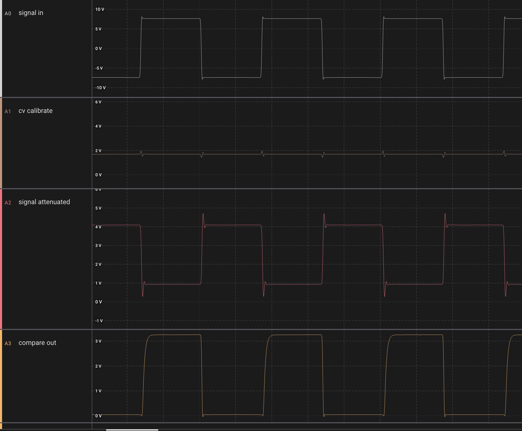
Max output of signal generator is +/-10.4V

Is attenuated and shifted to -0.3/+4.7V (inverted), so a full range input gives a 0-5V output, meaning we can compare bipolar amplitude of the whole signal using a 0-5V CV.

Input CV is 0 to 5V (or slightly less, around 4.6V as we're using a 47k/33k voltage divider from -10.8V)

10k pullup to +12V initially

Approx 2.5V CV gives the expected 50/50 duty cycle on the output

Rise time on output (with probe connected) is 1.5uS (with scope connected in parallel, rise time increases to 6uS). This is with a 12V output


Reducing CV to 0 completely turns off output

A signal that is always less than the comparator CV leaves the output fully on


A 3v3 pullup voltage (compatible with the teensy) gives a rise time of around 2.5uS when using a 10k resistor.

A 1k resistor instead gives a rise time of 560nS:


Something to remember: When doing comparisons on a slow moving signal, we may get multiple triggers during the transition. Here we compare a 8Hz triangle wave:


If we use a square wave instead, it cleans up - meaning frequency counting should be done using square waves (unless using hysteresis). This is a challenge if we intend to use resonance sine wave for frequency tuning the filter.

On the Logic16 probes I get double triggers even when sinewave frequency is as high as 10kHz (with the 1k resistor.

With the 10k resistor it seems that we're fine all the way down to 100Hz, some double triggering at 50Hz.

My thought is - double triggering is mostly important for frequency counting, which, when done with a square wave seems to work fine from at least 10Hz to 30kHz (probably even further) with a 10k resistor

For other cases we mostly want to do amplitude calibration, which does not care about doble triggers.

We do get a bit of ringing on the attenuated square wave input at 30kHz, let's see if we can remove it with a LPF:

When we put a 22pF cap in parallel with the 25k feedback resistor, we get this (cutoff is slightly less than 300kHz:


Hysteresis

With a 100k resistor from pin 2 to 7 (positive feedback) on the comparator, while still using the resistor divider on the CV input, we get a stable comparator even as low as 2.5Hz. However, the comparator CV changes wildly from 2.2 to 2.7V during switching:

When removing the voltage divider and just using the output from the CV buffer, the CV stays still but the double triggering is back:


But when removing the 100k resistor completely and just using the raw buffered CV, we reduced doble triggering to almost 0 even at 8Hz:


Then, with a 10pF cap in the positive feedback (between 2 and 7), double triggering disappeared completely, even at 1.5Hz


The output rise time however is increased to around 3uS:

Though - checking again without the cap but with direct CV buffer input, it still seems like the rise time is around 2.5uS. That means that adding the 10pF cap does not significantly increase the rise time.

Using a 50pF cap instead gives an even better result, but gives a rise time of 6uS.


Conclusion

There are a lot of unknowns when it comes to capacitance here, there may be capacitances on the breadboard that messes with my result. Even so, I think I'll try with the 10pF cap on the voice board.

EDIT:

Oooh, we have a serious issue here. The edge is not fast enough for the teensy, we get several interrupts per transition.

Even worse, once I remove the Logic 16 probe, we get a dramatic increase in interrupts, meaning the probe's capacitance filtered out a lot of noise. I need to revisit the hysteresis idea I think :-/


TODO: 

Check if hysteresis is available on the TCA9539, and if we can do frequency counting at 20kHz with the TCA9539. If not, we need to connect calibration directly to a pin on the teensy


Saturday, April 13, 2024

Calibration circuit

To be able to measure the bipolar amplitude as well as do frequency counting, I've come up with a very simple circuit:

It attenuates and shifts a full range signal, +12V to -12V, to 0 to 5V. The signal is inverted but that can be compensated for in the measurements.

The output of the circuit is then sent to a comparator where it is compared with a 0-5V CV, allowing us to detect amplitudes over the full 24V swing. In practice the swing will be +/-10.5V due to limitiations in the TL07x op amps, but that's ok.


Wednesday, August 2, 2017

DCO: Switching to JFET to try to improve low frequency amplitude

To try to fix the issue I'm having where the saw wave amplitude is too low at low frequencies, I decided to redesign the core using a JFET in place of the BJT that resets the integrator.

I found no p-channel JFET in my parts box, but I had plenty of the J112 n-channel JFETs, so to make things easier I decided to go with the yusynth design.

The Yusynth design however, has a 0-5V saw wave, whereas mine is 0 to -10V. To make sure things would still work, I changed the core ever so slightly to get a 0-10V:

instead of tapping the charge voltage directly from the DAC using a positive opamp buffer, I switched to a unity gain negative amplifier. This would sink current instead of sourcing it, changing the charging direction. To make this works one also have to replace the 2n3906 PNP transistor with a 2n3904 NPN (One should also switch the polarity of the timer output, but as both a positive and negative going spike are generated, just slightly offset in time, this was not required for testing).


But testing this, I got a big surprise - the low frequency amplitude was no longer too low - it was too high! Previously I had to increase the DAC value from 60 to 80-something, now I had to reduce it from 60 to 48 (steps times 5V/65536).

This made me less certain that switching to a JFET would improve anything, but I still decided to try it.

I added an LM311 comparator, and set its negative input to 0.118V using a 120k and a 4k7 resistor. This would assure that when the positive input was just slightly higher than 0V, the output would spike up to 15V, and when the input was 0V the output would be -15V - similarly to the yusynth circuit, where the comparator outputs a negative voltage to turn off the JFET. The circuit worked instantly (!), but as suspected, nothing changed.


So, now I guess I've ruled out the reset transistor as the cause of the offset. Also, the fact that the amplitude error changes when I swap the charging polarity, makes me believe that the cap is not at fault either (though I will still check this).

That leaves either the DAC (which is unlikely for the same reason as the CAP) or the opamp buffer.

It could also be that a small difference in the power lines (measured to +15.01 and -15.00 volts) could cause this, I don't know. I will try recalibrating and also try different opamps to see if that changes anything.

For reference: Here is the original breadboarded circuit with the 0 to -10V output. I have since added the missing 2R2 resistor, however, that changed nothing. The DAC is connected where the 20k pot is in this drawing


Tuesday, August 1, 2017

Yusynth VCO core discharging

I may have written about this before, but here goes:


The Yusynth saw core ramps down from 5 to 0v, then resets to 5v. the top of the charging cap is always at 5V while the bottom drops towards zero as current is sunk through the expo converter (u4).

The LM311 comparator has its positive leg grounded (when sync is not used). The LM311 is an open collector type comparator. For these, the rule, as written here, is that: 


"Current WILL flow through the open collector when the voltage at the MINUS input is higher than the voltage at the PLUS input.


Current WILL NOT flow through the open collector when the voltage at the MINUS input is lower than the voltage at the PLUS input."


When current does NOT flow, the output is pulled towards 15V via R20. When current flows, the output is pulled towards -15V which is connected to pin 1 of U5.


Pin 1 is called ground, but it can be connected to a lower voltage if necessary.


During capacitor charging, the voltage at the minus input is positive and thus higher than the positive input. In this case, current flows and the output is negative.

Once the negative input reaches 0V, for an instant, the input is lower than the voltage at the positive input, and current stops flowing. The output is then pulled towards +15V.

This would mean that as long as the output is negative, the JFET transistor is switched off, and once the output is positive, the JFET conducts, resetting the cap.

This is in accordance with what wikipedia says about an n-channel JFET:  "To switch off an n-channel device requires a negative gate-source"

 The source and drain of the transistor will always be between 0V and 5V, thus a -15V gate voltage assures that it is turned off. Similarly, source and drain will never be above 5V, so a +15V will always turn it off.

Since the source/drain may however reach 0V, the emitter of the transistor cannot be connected to ground - this would leave the comparator output and thus the JFET gate at about 0.6V, which is not enough to keep it pinched off.

DCO: comparator to reset period

I've been thinking about ways to enable frequency changes in the middle of a period without having to restart the period, which resets the phase.

My thought so far has been to use a comparator with a reference voltage set to slightly higher than the maximum amplitude of the wave, and reset the period once it triggers. That way we can reset the timer and set a new charge voltage anytime, and it will just slightly overshoot the desired amplitude. I would think that this could be a good solution, but it has some issues.

1) The amplitude may be temperature sensitive - if the capacitor charge time varies with temperature or if the charging current changes due to temperature effects on the resistor.

2) Setting such a reset point requires a trimpot and a way to check that the point is not set too low, in which case it would interfer with the normal operation of the DCO

As for 1), that is just something that has to be tested. But in case 2), it would be possible to let the microcontroller figure out the cutoff point by itself. If the MCU controls the reference voltage, it can loop through all frequencies (or at least a subset) and find the maximum amplitude during normal operation, then set the reference voltage to slightly higher than this. It would also be possible to rerun this operation later if temperature rises. The cutoff point may be found either using an analog pin, or it can be done using the comparator and gradually lowering the reference voltage until the comparator triggers.

The MCU has a built in comparator. It also has a built in DAC that can generate a reference voltage, but its resolution is only 5 bits. We need something better than that, but we do not want to add another spi controlled DAC or similar.

A possible solution: Use the built-in PWM generator in conjunction with a lowpass filter to generate a DC voltage.  This post, this article and this article has some filter suggestions.