Showing posts with label calibration. Show all posts

Sunday, April 14, 2024

Testing calibration circuit

Max output of signal generator is +/-10.4V

Is attenuated and shifted to -0.3/+4.7V (inverted), so a full range input gives a 0-5V output, meaning we can compare bipolar amplitude of the whole signal using a 0-5V CV.

Input CV is 0 to 5V (or slightly less, around 4.6V as we're using a 47k/33k voltage divider from -10.8V)

10k pullup to +12V initially

Approx 2.5V CV gives the expected 50/50 duty cycle on the output

Rise time on output (with probe connected) is 1.5uS (with scope connected in parallel, rise time increases to 6uS). This is with a 12V output


Reducing CV to 0 completely turns off output

A signal that is always less than the comparator CV leaves the output fully on


A 3v3 pullup voltage (compatible with the teensy) gives a rise time of around 2.5uS when using a 10k resistor.

A 1k resistor instead gives a rise time of 560nS:


Something to remember: When doing comparisons on a slow moving signal, we may get multiple triggers during the transition. Here we compare a 8Hz triangle wave:


If we use a square wave instead, it cleans up - meaning frequency counting should be done using square waves (unless using hysteresis). This is a challenge if we intend to use resonance sine wave for frequency tuning the filter.

On the Logic16 probes I get double triggers even when sinewave frequency is as high as 10kHz (with the 1k resistor.

With the 10k resistor it seems that we're fine all the way down to 100Hz, some double triggering at 50Hz.

My thought is - double triggering is mostly important for frequency counting, which, when done with a square wave seems to work fine from at least 10Hz to 30kHz (probably even further) with a 10k resistor

For other cases we mostly want to do amplitude calibration, which does not care about doble triggers.

We do get a bit of ringing on the attenuated square wave input at 30kHz, let's see if we can remove it with a LPF:
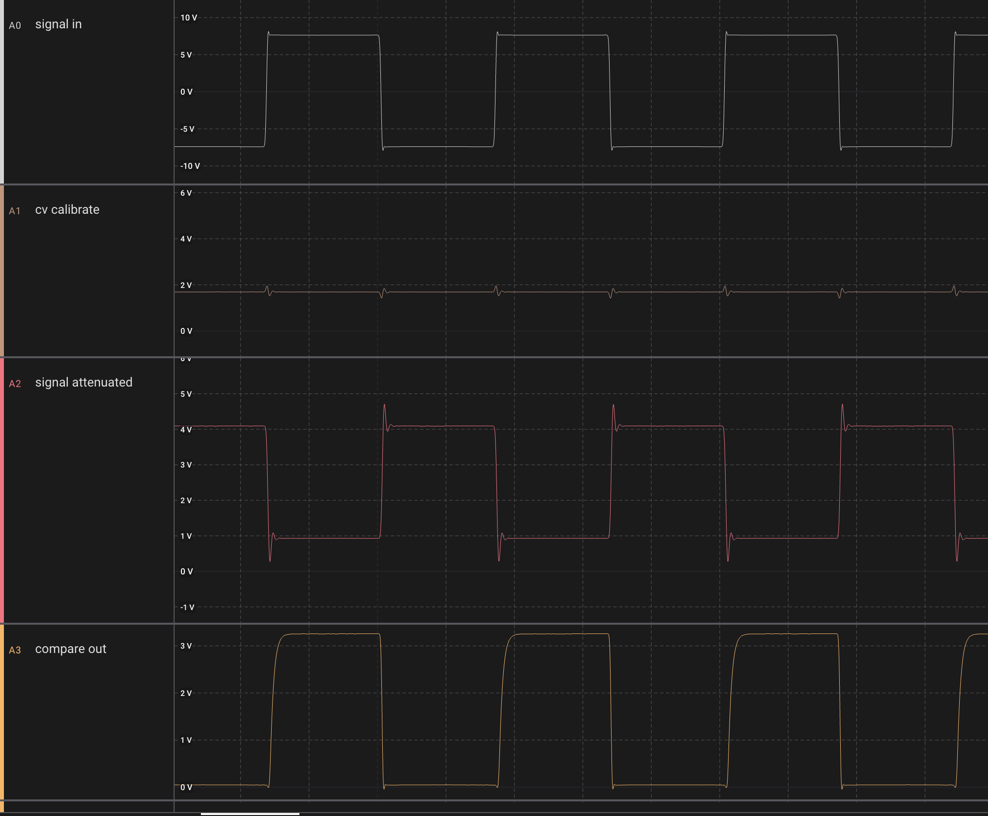
When we put a 22pF cap in parallel with the 25k feedback resistor, we get this (cutoff is slightly less than 300kHz:


Hysteresis

With a 100k resistor from pin 2 to 7 (positive feedback) on the comparator, while still using the resistor divider on the CV input, we get a stable comparator even as low as 2.5Hz. However, the comparator CV changes wildly from 2.2 to 2.7V during switching:

When removing the voltage divider and just using the output from the CV buffer, the CV stays still but the double triggering is back:


But when removing the 100k resistor completely and just using the raw buffered CV, we reduced doble triggering to almost 0 even at 8Hz:


Then, with a 10pF cap in the positive feedback (between 2 and 7), double triggering disappeared completely, even at 1.5Hz


The output rise time however is increased to around 3uS:

Though - checking again without the cap but with direct CV buffer input, it still seems like the rise time is around 2.5uS. That means that adding the 10pF cap does not significantly increase the rise time.

Using a 50pF cap instead gives an even better result, but gives a rise time of 6uS.


Conclusion

There are a lot of unknowns when it comes to capacitance here, there may be capacitances on the breadboard that messes with my result. Even so, I think I'll try with the 10pF cap on the voice board.

EDIT:

Oooh, we have a serious issue here. The edge is not fast enough for the teensy, we get several interrupts per transition.

Even worse, once I remove the Logic 16 probe, we get a dramatic increase in interrupts, meaning the probe's capacitance filtered out a lot of noise. I need to revisit the hysteresis idea I think :-/


TODO: 

Check if hysteresis is available on the TCA9539, and if we can do frequency counting at 20kHz with the TCA9539. If not, we need to connect calibration directly to a pin on the teensy


Saturday, April 13, 2024

Calibration circuit

To be able to measure the bipolar amplitude as well as do frequency counting, I've come up with a very simple circuit:

It attenuates and shifts a full range signal, +12V to -12V, to 0 to 5V. The signal is inverted but that can be compensated for in the measurements.

The output of the circuit is then sent to a comparator where it is compared with a 0-5V CV, allowing us to detect amplitudes over the full 24V swing. In practice the swing will be +/-10.5V due to limitiations in the TL07x op amps, but that's ok.


Tuesday, January 10, 2023

DCO Calibration issue

After fixing the issues with calibration related to the compiler bug, I hoped everything would go smoothly. Unfortunately that was not the case.

After calibration, when running through frequencies, I would sometime see a kind of discontinuity, where the wave amplitude would drop to zero and then build back up to the correct height again over two periods. 

I looked at the DAC charging voltage and could see a kind of asymptotic behaviour where the charge voltage suddenly rose much faster than it should, and when it reached max, dropping back to zero but still rising with the same speed. Clearly the DAC output overflowed.

DAC Voltage error. The first little drop is only due to missing calibration. The asymptotic looking one is where the interpolation overflows and voltage drops to 0.


It took some testing to figure out what was going on: For a single sample in the calibration, the dac voltage was detected significantly lower than it should, and more importantly, lower than the previous sample. This meant that the slope multiplier should have been negative. But the slope multiplier is unsigned, so it overflowed and ended up with a large positive number instead.

Then, when interpolating between the two values, we would add a large number instead of subtracting, leading to the spike (and DAC overflow) we saw.

But why did we get the wrong value during calibration?

It happens during the first cycle of a single note calibration. For some reason, we detect that the wave amplitude is too high - higher than the comparator voltage - when in reality it is not. This leads to the binary search continuing in the wrong half of the voltage range and the calibrated voltage ends up being around 32768 instead of what it should have been.

DAC voltage calibration - 7th cycle starts off too low and never reaches back up to the correct voltage.


Debugging the issue is a pain in the ass, because we are dependent of the wave being reset at exactly the same point every time. If something changes, the voltage may not cross the comparator voltage, and while it seems we have fixed the error, it still might be there.

I strongly suspect that what happens is that the voltage reaches the comparator voltage AFTER we have changed the dac and timer to a new frequency, but before the interrupt handler resets the wave. My fix was to move clearing of the comparator flag into the interrupt routine, so we are guaranteed that a comparator interrupt stems from the current cycle, NOT anything before it. It looks like it works but who knows...

I also saw another strange thing - some of the cycles are of different lengths than they should be, by as much as +2us. But then, often the next cycle or the one after that is a bit shorter. I have not been able to properly explain what is going on. I suspected that the comparator interrupt may have been part of it, that it triggering would make the program enter the interrupt routine before the timer interrupt, and then staying there for long enough to delay the timer interrupt, but I have not been able to confirm this. My fix was to disable comparator interrupts once we get it once during the calibration period, to prevent the code from reentering the interrupt routine due to the comparator interrupt being high. When this was NOT done, we would probably enter the interrupt routine repeatedly until the timer interrupt fired and disabled the comparator.

Now everything seems to work properly and I've started working on a verify routine, one that runs through frequencies where I suspect the charge voltage may be too high (such as in the middle of interpolation) and checking if we hit the comparator voltage during normal operation.

Low range sweep after calibration

High range sweep after calibration


I do however suspect that that is not the case. Had the timer been exponential between two key points and the voltage linear we would see an error, but both are linearly interpolated meaning the voltage should match the frequency fairly well. 

We have another error too - a strange falloff at the end. The charging voltage is too low even if the DAC has not maxed out. The consequence is rather low as this is in the > 20kHz range but I still want to figure out what is going on.


Saturday, June 20, 2020

The VS-1 compared to old and new analogs. Technical details

I just watched an amazing video from Abstract Instruments, the makers of the VS-1: https://www.youtube.com/watch?v=4WwXlRYw_S0&feature=youtu.be.

It compares implementation details of the OB-X, JP8, Prophet 5, Rhodes Chroma and OB-6 and gives tons of useful information. I've tried to summarise it here:

Autotune

Autotune can only do so much for high frequencies, so a good initial trim is essential (for all synths)

JP-4:
Has no autotune, relies solely on the trimmers

OB-X:

  • Measures C5 (around 1kHz), does not adjust scaling, only initial tune offset.
  • Measures each oscillator twice: Once to measure frequency, second to
  • confirm the adjustment. Measures up to six times, if that fails it disables the voice.
  • Autotune takes < 2 sec


DAC:
  • 0 to 5.333V
  • 5.333V / 64 notes = 83.3mV step over 5 octaves, 1V/octave
  • 10 bit but only needs 6 bits to represent 5 octaves
  • In addition: Common VCO frequency CV, 4 octave and 1 octave from left hand control panel for a total of 10 octaves
  • Oscillator bias CV runs through 10M resistor (on a 100k for 1V/oct style summer)


P5 DAC:

  • 7bits, 10.666V reference = 10 octaves, 83.3mV, 1V/octave
  • 7bits fine tune for a total resolution of 14 bits


Rhodes Chroma

  • 12 bit main DAC for CVs, 3 cents resolution (reasonable for the time)
  • 8 bit that sets reference voltage for main DAC, skews tracking, corrects scaling errors in 0.1% intervals
  • Measures the periods at 6 octave intervals for each oscillator [error, should be 6 something else??]
  • Calculates scaling bias (done in 8 bit dac). Also calculates initial tune offset added to main DAC


Prophet 5

  • Rev 1 & 2:
  • Four checks: C3, C4, C5, C6
  • Bias CV resolution is about 1 cent with 128 possible values, about 1 semitone range
  • 7 bit bias CV dac mixed through a 10M resistor (on a 100k for 1V/oct style summer)
  • 40 autotune measurements (4 points x 10 CVs). Takes a long time. ( > 10 secs)
    • Bias CV 1 is used for bottom up to 1/2 oct above C3
    • Bias CV 2 C4 +/- 0.5 octave
    • Bias CV 3 C5 +/- 0.5 octave
    • Bias CV 4 C6 - 0.5 octave and up


Rev 3:

  • 7 checks per osc: C3-C9
  • 14 bits bias CV added as parts of Key CV, resolution is 650uV or 0.8 cents
  • Bias for C0 to C2 is calculated from the others as it takes too long to measure ( > 60 secs)


Jupiter 8

  • 10V output, 3cents/step for 12 bit, < 0.8 cents for 14 bit
  • Measures C3 and C8, uses a formula to calculate a bias CV for each key


Sequential OB-6

  • samples several points and deriving a high resolution correction curve
  • temp sensor, saves temp profiles
  • can recall profiles, does not do any real time calibration per se
  • has "slop" settings to introduce variation


Analog voices

OB-6:

  • No trimmers, everything is done through CV
  • Sub osc on VCO1
  • Can mix waveforms using 2164 VCA
  • Taps all poles of HP/BP/LP filter, mixable using 2164
  • 2164 for resonance control
  • 2164 for panning
  • Splits after voice mix to dry and fx which is mixed afterwards

VS-1:

  • 2164 panners
  • Bi-timbral
  • 4 input analog chorus
  • Analog polyphonic glide

Digital control


  • OB-X: 2.5MHz MCU
  • OB-6: 32bit PIC at 200MHz
  • VS-1: 32bit ARM at 600MHz


Reading/updating CV:

Loop times:

  • OB-X: 14-19ms
  • P5: 9-11ms
  • JP8: 3-6ms


OB-X

  • Pots are scanned using a DAC and a comparator (successive approximation)
  • 10bit CVs, 10 iterations per pot
  • 1-6ms to scan pots (19 on OB-X)
  • Scans pots then updates CVs, thus updating CVs less frequently when loop time is long
  • More complex sample and hold circuit for pitch CV (check, possibly just shifting voltages?). Low leakage polystyrene caps for pitch CV assures stability between updates.


OB-6

  • 12bit ADC over SPI to scan pots and external CV input, pitch and mod wheels. Scanned 256 times per second.
  • Updates CVs at 24kHz - must be fast to update software LFOs and envelopes fast enough
  • 24kHz gives sub 1-ms attack times for 0 to 5v envelopes (looks like 2.5v to me in oscilloscope pics)
  • Smooth LFO rates up to 500Hz
  • Looking at the oscilloscope screenshots, a full attack takes around 0.4ms-0.5ms (each grid line is 0.2ms), at approx 5 samples per 0.2ms (= 24kHz), giving 10-13 samples for attack.
  • Uses pair of 8ch 16 bit dacs for 120 CVs
  • Uses independent CVs per voice instead of common CVs, to be able to add offset biases on a per voices basis, it has NO trimmers!
  • 4051 multiplexers for sample & hold
  • S&H caps on mainboard, S&H opamps on voice cards
  • Separate microcontroller for CV updating, tables in memory for calibration
  • Core logic runs at 1.2V
  • Samples VCO and filter waveforms using 24bit ADCs, AKM 24bit stereo codecs


VS-1

  • CVs updated at 48kHz
  • Single 8 ch DAC
  • 85 CVs
  • Single ADC to scan the endless pots, scan rate is 1kHz

Friday, August 4, 2017

DCO: Culprit found but not fixed

I did extensive testing of various op amps yesterday, and as suspected, the amplitude error at low frequencies is caused by the op amp. I also tried recalibrating the power supply but that had no effect whatsoever.

The results from various opamps varied wildly, and results from positive and inverting buffering configs also varied a lot.

My best hit was with a UA741, in inverting mode the amplitude was perfect across the entire frequency range! Unfortunately, it was only a lucky strike, I retried several other UA741s and the result varied from around 7 to around 13V amplitude (when the real amplitude should be 10V).

The conclusion then is that at voltages very close to zero will experience a lot of variation even between specimens of the same family.

Tested op amps

UA741 variations

I am not sure how the effects are over time and temperature, this must be tested.

If  the effects are mostly production variations, it would be possible to calibrate each DCO.

This can be done in code even if DAC lookup tables must reside in program memory due to RAM limitations (1kB of memory is required for DAC keystep and rise-per-substep tables and the MCU only has 1kB of RAM in total). The PIC16F allows programmatical/runtime writes to flash program memory, and though there is a limit to the number of times this can be done (>10 000), even a write on every system startup would probably be possible.

Hopefully though, calibration will seldom be necessary. As a nice side effect, calibration will correct variances in both charging caps and resistors as well as opamps.

Calibration

Here is how I imagine it to be done:

A reference voltage is applied to one of the MCU pins. This is used as the reference voltage of one of the internal comparators.

First, apply the lowest frequency. By increasing and lowering the DAC output voltage until the comparator changes polarity, we figure out
- if the voltage is too high or too low
- if the amplitude error is within acceptable limits

A slightly too low amplitude is acceptable but a too high amplitude is not as this will trigger the comparator during normal operations, if we choose to use it as a reset-on-frequency-change trigger. The amplitude must also be adjusted to always be slightly lower than the comparator trigger point to prevent false triggers.

We also have to consider measuring the highest frequency amplitude error to see if errors are always either high or low. For now, I'll assume that they are always one or the other.

After finding the initial error, one loops through the remaining 255 samples, starting from the bottom.

For every frequency, the DAC voltage is increased or lowered (based on what we found for the lowest frequency) until the comparator changes polarity - this gives us the "correct" value for that step. To save time, we may stop checking once we reach a frequency where the error is small enough (and lower than the comparator voltage).

We should now have a correct lookup table for key samples. All that is needed now is to calculate the interpolation lookup table, and write everything to non-volatile flash memory.

To minimise the number of recalibrations, we could let the DCO check the keysamples on startup. If they are still within limits, no recalibration is necessary.


A different approach to finding the current amplitude would be letting the DCO control a PWM-based DAC to generate the reference voltage. It could then change the reference voltage instead of DAC output value to find the amplitude. Not sure that it's a better approach though.

PS:  If the signal amplitude is 10V, using a resistor divider with R1 = 100k and R2 = 68k will get the amplitude down to 4.048V. This lets us use the internal 4.096V voltage reference with the comparator.