Showing posts with label LPF. Show all posts

Saturday, May 23, 2026

Moog filter trimming

 At the moment, the moog filter has to be at full output to match Juno. That may change.


Also, to get a proper amplitude out, the trimmers has to be set as follows:

4p: 4.95V

2p: 1.67V

reso: 5V.


Even with this, the output signal jumps up and down when switching between juno and moog, indicating that it is not properly centered. Check the signal at filter output to see the real centering. 

Friday, January 31, 2025

Filters clipping - current situation and solution

All three filters clip but some are more extreme than others.

Juno clipping

The Juno filter has a major flaw, it has an output gain stage that clips for anything above 2V out. It outputs 2V from 10V in, which means that all resonance is clipped if it exceeds the max input signal.

JP6 clipping

The JP6 filter clips in the output selector/gain stage, but also slightly internally

Moog clipping

The moog filter clips the least as it has a fairly good soft clipping built-in. The output gain op amp still clips at extremes.


Fixes

I've worked a lot to find the best solution the last few days, and as such has come up with the following approach:

Bus mixer changes

Reduce amplitude from the bus mixer into the filters from max 10V to max 5V. This requires two changes:

- Double the input resistors to the wet/dry amps in the bus mixer, halving the output of the summer

- When turning on serial instead of parallel filters, disable input from sum B. 

- SVF must still somehow have unity gain, if not, chaining input will be too low.

This alone has a huge effect on most clipping, giving double the headroom. 


Reduce the post filter gain

Moog filter

For the Moog filter, this is simply done by using half the CV. It can be done in software for the current version. This stops any leftover clipping in the Moog filter.

Juno filter

For the Juno filter, we add a resistor to the output. This will end up in series with the 18k resistor in the post juno filter gain stage, and reduce the gain. A 22k resistor reduces gain from 5.5 to 2.5. This takes away most of the clipping, though the filter still clips when the resonance oscillation has the same frequency as the input signal. It does however require modification of the juno filter board. This requires some other mechanism, like soft clipping the signal. More on that later.

JP6 filter

For the JP filter, we need to keep unity gain through the filter, so we do the gain reduction in the output mixer. It does not prevent any clipping but is required to keep max levels the same as for the juno and moog filter. This is the simplest solution for now. 


Reducing JP clipping

Unfortunately, the JP filter clips very slightly at highest resonance at the point where oscillation is in sync with the signal. This is not easily changed as it happens inside the filter circuit, but it is also the least serious clipping. I will leave it as is for now. It also goes away if reducing the max input slightly, but requires at least another 20% reduction. Perhaps this is best done in software for now.

To prevent other clipping, we have to change the output gain that happens around the output selector. This can be done in two ways: 

- Changing the voice card. This is the correct solution, and should be done for future versions of the card. Gain for all but the BP2 cell is 100/65 = 1.54, so quite a bit of clipping can be removed here. We still may have to add some kind of soft clipping, though. If soft clipping is added, we may choose to reduce the input by the needed 20% and increase the output gain instead to get around the initial clipping.

- Making a drop-in-replacement for the IC56 DG408 mux that halves the output by adding more input resistors. Unfortunately, the maximum BP2 output is 8.6V, and this is followed by a 1.67x gain stage (IC52A) which immediately clips. This cannot be remedied by the card. Instead, we need to reduce the BP2 gain stage to unity by adding an output resistor > 39k (to make the sum of 56k + 3.9k + x = 100k) to the JP6 BP2 output. It may be possible to do with existing JP6 filter cards or we can order new cards with this modification, and use the current version with new voice cards.


TL;DR - these are the needed fixes

- Double the signal input resistors on the wet/dry mixer on the bus mixer board

- (fix the gain error on the bus mixer board)

- Reduce output amp gain for Moog, JP6 and Sines to 50% (in software)

- Set a max resonance for all filters to keep self resonance oscillation amplitude as low as possible.


To save the current voice cards

- Add a 22k resistor to the juno output boards (for this version).

- Double the Moog resonance CV somehow, possibly by adding a parallel resistor to the CV input to double the current.

- Create a drop-in for the DG408 JP output selector that reduces gain (and possibly adds soft clipping?)


For new version

- Replace the 18k juno post filter gain input resistor with a 39k one (or rather, move the post filter gain onboard the Juno filter PCB).

- Add soft clipping to the juno filter

- Fix Moog resonance CV on the moog board

- Update the circuit around the JP filter output selector to prevent clipping. May have to add soft clipping.


PS: Self oscillation with a very high frequency (>20kH<) makes what sounds like digital noise. Not sure exactly what to do with it, maybe a lower frequency output LPF would be a good idea.

PPS: There are a lot of weird things happening that may be caused by the ground plane noise from the waveshaper. 

PPPS: Knocking on the breadboard makes resonance wobble. I hope this is just poor connections but fear that some of the ceramic caps are picking it up. We'll see.

Monday, July 29, 2024

New PCBs from JLCPCB - Voice card ++

All new cards. Top left: Bus mixer, VCO and Juno filter. Top right: Moog and Jupiter filter. Center left: Voice mainboard. Center right: 2X waveshaper, FX module and bus mixer angled connector. Bottom: CV board
 
Everything mounted together. Looks a bit Frankenstein-ish but it fits!

Even the Juno filter, sandwiched between the voice card and the Moog/JP6 filter fits. I wonder how hot it will get though.

A true beauty!


Monday, February 13, 2023

Tuneable filter with 14 octave span

I intend to make the juno filter tuneable in software. To do this, I hoped to add a 20 octave range to the CV and just use that. But simulating the filter gave a few surprises:
- when using a 25k input resistor to get 20 oct range, the output of the initial op amp exceeds the rails, so it will clip.
- the maximum cutoff for the filter at the current implementation is around 48kHz
- Below 7-ish Hz the filter acts like a band pass filter so the input is always attenuated, meaning lower frequencies are not possible.

Now, the two last facts are not a big problem. They happen on the filter side of the exponential converter, which is not as temperature sensitive so range hopefully won't change that much with temperature.

The expo converter however will change a lot, meaning the input needed to get a certain output will not stay the same. THIS is where we need to apply tuning relative to temperature.

So what I need to look at is the circuit before the expo converter transistor pair. I need to make sure that THAT can go above and below what is needed for control at 25 degrees celcius. To do this I've started out mapping out what currents into the filter core gives what cutoff. Here is a short table:

2mA = 47.2kHz
1.5mA = 45kHz
1.2mA = 43.5kHz
1.1mA = 42.5kHz
1.0mA = 41.5kHz
0.8mA = 38.6kHz
0.7mA = 36.5kHz
0.6mA = 34.2kHz
0.5mA = 31.3kHz
0.4mA = 27.3kHz
0.3mA = 22.5kHz
0.2mA = 16.3kHz
0.1mA = 8.7kHz
50uA = 4.4kHz
25uA = 2.23kHz
12.5uA = 1.11kHz
6.25uA = 553Hz
3.125uA = 274Hz
1.56uA = 136Hz
781nA = 67.4Hz
390nA = 33Hz
195nA = 16Hz
97.7nA = 7.64Hz
48.8nA= n/a, alltid under -3dB

So... from around 100nA and up to 0.2mA, the tracking seems to follow the rule of doubling the current = double the -3dB cutoff point. After that it falls off a bit. I think that a range of approx 4-40kHz is fine, that's about 13.5 octaves. 

That means that the input range we're looking for is about 100nA to 1.2mA. Next up will be looking at the circuit as it is and see what the input to the expo converter is at these currents. Then I'll see if I can change how the circuit works to allow the input to go lower and higher than this. At a stable 25degrees this won't have any impact (it simply won't work), but it will allow us to correct for changes later. Maybe.

A bit more testing

I did some more measuring and calculations today. First of all, I calculated the necessary resistor to get 1V/oct response. The Juno uses a resistor voltage divider with a 560Ohm tempco at the bottom. To get 1V in = 17.9mV out (17.9mV is the magic number for expo converters at 25C), the top resistor needs to be 31.745k to get perfect tracking. In the current design this is achieved by a 20k multiturn pot combined with a 10k and 8k2 resistor. 

In the 12V version of the filter, we have a few issues.

Without any changes, Iabc tops out at 1.07mA. We need at least 1.16mA to reach 40kHz.
Allowing a 20V input (or rather, changing to a 25k input to get 20 octaves from 5V input) will not work as the cv input opamp output will hit the low power rail (-12v) before going all the way.

So, what can be done:

1) By switching the 10k input resistors on the LM13700 Iabc inputs for 8.2k ones, we get a max Iabc of 1.3mA

2) By decreasing the top resistor in the resistor divider, we can get a response that is lower than 1V oct, for example 0.8V/oct. This means that the range output by the cv input summer can be within the power rails. 

I did some inital trials without calculating too much. For easier reading I use a 0-20V CV input with a 100k input resistor. Swapping R34 with a 5k (reducing the top resistor by 5k) and replacing 10k Iabc resistors with 8.2k, I get a CV AFTER the summer that goes from 6 to -10V (at 15.6V input). The Iabc response goes from 25nA at 0V to 1.3mA at 14V. 150nA, which we know from earlier is about the lowest we need, is output at 2V input. 

20V CV input and around 0.8V/oct tracking. +/-12V filter

Red: CV input, Green: Voltage after summer, shows saturation at around 16V CV. Blue: I_abc, tops out when CV is around 14V.


This means that our useable range is around 12V, from 2V to 14V, and that we have around 2V above and below this. We already have a fairly useable tuning range.

So, what should I do next?

Given 20V in and 100k input res (will be changed to 5V/25k)

1) Find the range we need for 14 octaves (150nA to whatever)
2) Find a gain + resistor divider that puts 3 V in at 150nA and 17V in at whatever is needed for 14 octaves up.
3) Input summer must not saturate, eg. stay within +/-10V output for the full range.

This will be fun!

BUUUT. What about the tempco resistor? Will it still adjust itself correctly when the top resistor is no longer the same? Well, that needs to be checked. 

And for later: At what input audio does the filter start to distort?

EDIT: Input to expo conv: 72mV in = 150nA out, -159mV in = 1.16mA out

Sunday, February 5, 2023

High frequency filtering in audio output

One thing that I've put off for a long time is selecting filter caps for various op amp output drivers. 

Today I had a look at some datasheets to figure out what others are doing. 

Generally, it seems that filtering (by putting a cap in parallell with the feedback resistor in an inverting op amp) is only done at the last stage of the circuit, not within the circuit itself. It seems that very little filtering is done except for biasing using electrolytics in the audio path to center the signal. I assume the final filtering is just to stop radio frequencies, stuff that we don't want to escape the circuit perhaps?

Here is what I found

Self on audio (book) page 237: 100pF/4k7 = 339kHz

Self on audio (book) page 359: 27pF/10k = 589kHz

JP8 source mix: 10p/100k = 159kHz

JP8 VCA cont 15p/100k = 106kHz

Juno 6 out: 47p/3k3 = 1.02MHz - See juno 60 where the 3k3 is actually crossed out in the schematics and 27k written instead.

Juno 60 out: 47p/27k = 125kHz

Juno 106 out: 22p/33k = 219kHz - Interestingly enough, and supporting of my theory that filtering only happens at the last stage, the 106 has the same feedback resistor as the Juno 6 (3k3) right after the filter, but no cap, as it has a mixer at a later stage too, mixing in High-pass filter.

JX-3P out: 330p/10k = 48kHz

JX-8P synth mix: 100p/47k = 33.8kHz

JX-8P chorus: 100p/22k = 72kHz

THAT4301 reference: 47p/20k = 169kHz

Sooo, I can't say that the findings are exactly conclusive. Before starting this research I suspected that the cutoff would at very least be above 22kHz (being the upper limit of human hearing) and perhaps at least the double as we want to make sure to not remove anything wanted. Most of these results seem to support that, with roland ranging from 33kHz up to 219kHz (disregarding the Juno 6 which seems to be too high). I'd say somewhere between 100 and 150kHz is probably a nice compromise.

Now, I started looking at this to find a good cap for my distortion circuit, which has an output feedback resistor of 120k. Playing around with various caps and looking at the output of the scope, it seemed like 10p would give a result where frequencies up to 22kHz did not get much attenuated. Calculating the cutoff using 120k/10p gives 133kHz which incidentally fits nicely between 100k and 150k.

That said, as the distortion is in the middle of the circuit, I may as well skip filtering alltogether.

Friday, December 4, 2020

Tons of new circuits ready!

So much has happened this summer and fall, and I haven't written about half of it! Some of it is directly related to the XM8, but most is utility circuits. I simply decided that I had to take time to do do some intermediate steps before building the final voice cards.

A shortlist of circuits I've designed, breadboarded, tested and finally produced at JLCPCB/DirtyPCBs follows below. Everything has been soldered by my good friend and colleague Stig-Rune!

Analog CV bank with 16 CVs in groups of 4.


For each CV you can select between lin or log/antilog  response, as well as uni or bipolar operation. Per group of four you can select the CV range, 0 to 2.5V, 5V or 10V (or +/-2.5V etc for bipolar). I did fuck up the PCB slightly so I had to cut a trace in three places and solder a wire. Also, I messed up a cable so I shorted the outputs, almost overheating the opamps. After that it worked perfectly. Output is via 10 minijacks and a 10p IDC connector for easy connection to a breadboard.


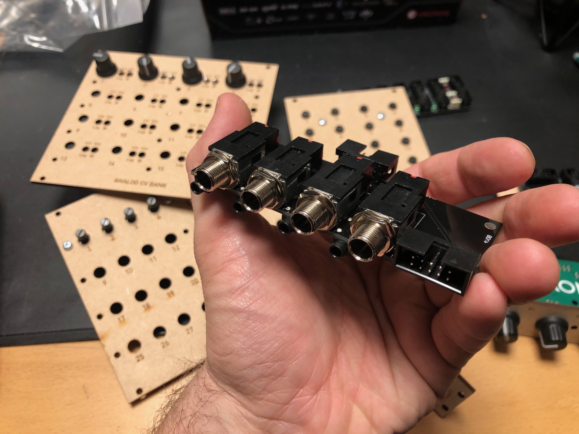
Quad input/output module with 1/4" jacks


For each module you can select input or output connected to the 1/4" jack, and the opposite will be connected to a minijack. Both ends are also connected to a 10p IDC connector for easy connection to a breadboard. For each channel there is an option of 10 or 2 x attenuation and 10 or 2 x gain, meaning you can either have a unity gain circuit, a 5x attenuation (for line out-ish) or 5x gain (for input).


24/48 button module, digital

A digitally scanned button module (without the microcontroller), chainable for up to 48 buttons. Serially read so it only requires four pins + power, making it possible to combine it with the potentiometer module on the same cable.


8 to 64 potentiometers module, digital


A digitally scanned potentiometer module (without the microcontroller). Each module has 8 potentiometers, and 8 modules may be chained for a total of 64 potentiometers. As with the button board, it only requires four pins, and it shares the same clock and reset pins at the button module so a total of six pins + power is needed for all digital modules. During testing I discovered that pin 9 on IC2 - one of the address lines - should have been connected to GND. Now it is floating, so it isn't possible to set the address correctly. It's an easy fix however.


4 x IDC Passthrough module

A simple panel with IDC connectors on both sides, makes it possible to route IDC connectors as a group through the front or back panel without putting the cable through a hole.


Bitcrusher

A combined 12 bit sample rate reducer and bit rate reducer with analog and digital control, based on a PIC16F18446 microcontroller with built-in ADC. Described in separate posts. I've ordered 25 of these.


20kHz LPF

A filter module that can be used as an anti-aliasing filter for ADC input and reconstruction filter for DAC outputs. I use the same configuration in the Bitcrusher and intend to use this for the combined DCO/wavetable oscillators. The circuit comes from this page: https://www.analogfilters.com/anti-aliasing-filter/


Voltage Controlled Distortion

A distortion module for the XM8, the second of the two pre-filter FX (the bitcrusher being the other). Controllable distortion amount and output amplitude, as well as switch between hard and soft distortion. Untested.


Memory


A DIL mounted SMD chip, 128Mbit, for use as sample memory for the wavetable oscillators etc. Untested.


Prophet VS keyboard controller

A new revision of the 68b01 clone for the Prophet VS. I've ordered 20 of these so I have for future sales. They have all been programmed but are missing legs.


Modular synth power bus board

16p Doepfer standard boards with 7 connectors. A bit short but cheap to build.


10p and 16p breadboard IDC connectors

Tiny boards with an IDC connector on one side and legs on the other, making it easy to use ribbon cables between breadboards and modules


Unbuilt designs

In addition, I have PCBs for the following that has NOT been soldered yet:


Breadboard power and I/O module

Has input for +/-15v and a regulator for 5V. Also has IDC connectors for chaining multiple boards, and small chain-boards that can be fitted upside down to connect multiple boards. Connects to the power busses on the breadboard. No more risk of messing up polarities! Also: a 10p Doepfer compatible power connector, although the doepfer uses +/-12V, not 15V, and a 10p I/O connector that connects a ribbon cable to 10 pin headers for easy and stable connections. Pin 10 may be connected to ground with a jumper.


Breadboard coax connector and I/O module

A board with four coax connectors and the same 10p I/O connector as the board above. Will give stable connection points for oscilloscop, function generator and other gear that uses coax.


15-to-12v DC converter module

A module that converts +/-15v from either a molex connector or a 10p IDC connector to +/-12v and +5v. Output is through a 16p connector, compatible with the Doepfer standard. Also has a two pin header for injection of Gate and CV 


All in all 16 different boards! Needless to say, I'm more than pleased! I'm getting so close to being able to test an initial voice board, I just need to program some digital envelopes.


Bonus

I finally got the following soldered and ready for testing:

Two versions of the sample and hold buffer, one with some large caps and some filtering and one in a tiny DIL14 format, both quad sample & hold:


Then the second version of the DCO, this time with DAC output to make it a wavetable oscillator too: