Showing posts with label button. Show all posts

Wednesday, September 24, 2025

Cleaning up the UI

I'm about to make a prototype of the UI, and have been cleaning up the grid a bit. This is what it looks like right now:


Inspired by the Matrixbrute, I started adding boxes around the related parts. The spacings are way off, but it should give some idea as to how things are grouped:


I do have some problems with this though. The vertical slits don't line up, in fact, they make the whole thing look a bit messy. 

I did also make a ready-for-lasercutting mode, that adjusts all line thicknesses and changes pot and button sizes to fit the shafts, ready for prototyping. Here is the left panel again:


 Now, to see if I could do any better, and after looking at the Waldorf Quantum, I came up with the following (crude) version


 It follows a slightly more logical structure, with the sources top left, then the mixer and post-mixer effects. It also groups the LFO and Arp in two separate two-row areas which gives a nice balance. There is not quite enough room for everything, especially the Arp controls, and I've decided to remove the bit crusher level pot as it isn't particularly useful. I do like this quite a bit. 

Then I decided to color the current version too, and to my surprise, I think it looks cleaner than it did with the "real" colors:

I think I can make both versions work. I will prototype the finished version now, and perhaps I'll have time to revisit the second version in the future.

As for the right side - it also needs a bit of cleanup, there is no room for the frame here, and I guess I should redo the filter to work better visually on the 8 row grid if I choose to go with the modified left side. 


I also think I'll probably ditch the post-filter bit crusher as that can be done by a general DSP, and maybe I'll make a smaller group of pots and no screen (or small oled screens?) for the DSP part. I have even been thinking about doing per-voice FX, or at least chorus, though that would mean not using the FX send lines. We'll see.

Thursday, January 9, 2025

Button scanner utility board

I've made a chainable button scanner board, similar to the one for potentiometers. Each one connects up to 64 keys/buttons through 8 connectors. When clocked, button statuses are output on a single pin. 

The button status is inverted, so a pressed button reads as 0/GND, an open as 1/V+ 


In addition, a breakout board is available, converting 8 columns + common row to 8 column pins + 8 row pins, making it easy to connect buttons using Dupont connectors.

The breakout boards are made with surface mount connectors to have a flush back, making it easy to glue/tape them to the back of the panel, close to the switches.


Monday, March 29, 2021

From 3.3mm square to D-shaft

I've bought a ton of 10mm button caps in black sandblasted aluminium. They match my larger potentiometer caps perfectly and I want to use them as potentiometer caps. Only problem is, they are meant for 3.3mm square shafts, not D-shafts, so I had to find a way of replacing the insert inside.

I've experimented with various sizes of 3D-printed inserts and this is my best result:

The inner diameter is 6.2mm, the outer is 7.9-7.95.   

7.95 works with press fit, but 6.2 inner and 7.95 outer made the part stick too hard to the shaft.

6.3 was too loose for the plastic shaft but may work on the metal one - however, there we need a section without D as the D-part is much shorter.

I didn't have time to try 6.25.

The insert height is 9.5mm. The inner height of the cap after removing the existing plastic is barely more than this. However, this seems like the perfect height - it leaves a 2mm gap on the prototype, but that prototype is 2mm lower than the button prototype, meaning that it will be a perfect match if the panel is similar to the button prototype.

The turning force necessary for the metal pot with this 10mm cap is actually ok. Quite heavy but a certain quality feel. The plastic shaft on the other hand feels a bit too light, especially when compared to the bigger caps on the metal pot. However, it is comparable to the force necessary on my other gear (Prophet 5, Little phatty) so I need to make a full mockup to try it properly.


I removed theexisting insert by 

- Drilling a 10mm hole in a wood block, then cutting it in half to make a clamp.

- I then put the clamp around a cap and inserted it into a vice to prevent the cap from rotating during drilling

- Then I drilled a progressively larger hole - 5mm, 6.5mm and finally 8mm.


Friday, December 4, 2020

Tons of new circuits ready!

So much has happened this summer and fall, and I haven't written about half of it! Some of it is directly related to the XM8, but most is utility circuits. I simply decided that I had to take time to do do some intermediate steps before building the final voice cards.

A shortlist of circuits I've designed, breadboarded, tested and finally produced at JLCPCB/DirtyPCBs follows below. Everything has been soldered by my good friend and colleague Stig-Rune!

Analog CV bank with 16 CVs in groups of 4.


For each CV you can select between lin or log/antilog  response, as well as uni or bipolar operation. Per group of four you can select the CV range, 0 to 2.5V, 5V or 10V (or +/-2.5V etc for bipolar). I did fuck up the PCB slightly so I had to cut a trace in three places and solder a wire. Also, I messed up a cable so I shorted the outputs, almost overheating the opamps. After that it worked perfectly. Output is via 10 minijacks and a 10p IDC connector for easy connection to a breadboard.


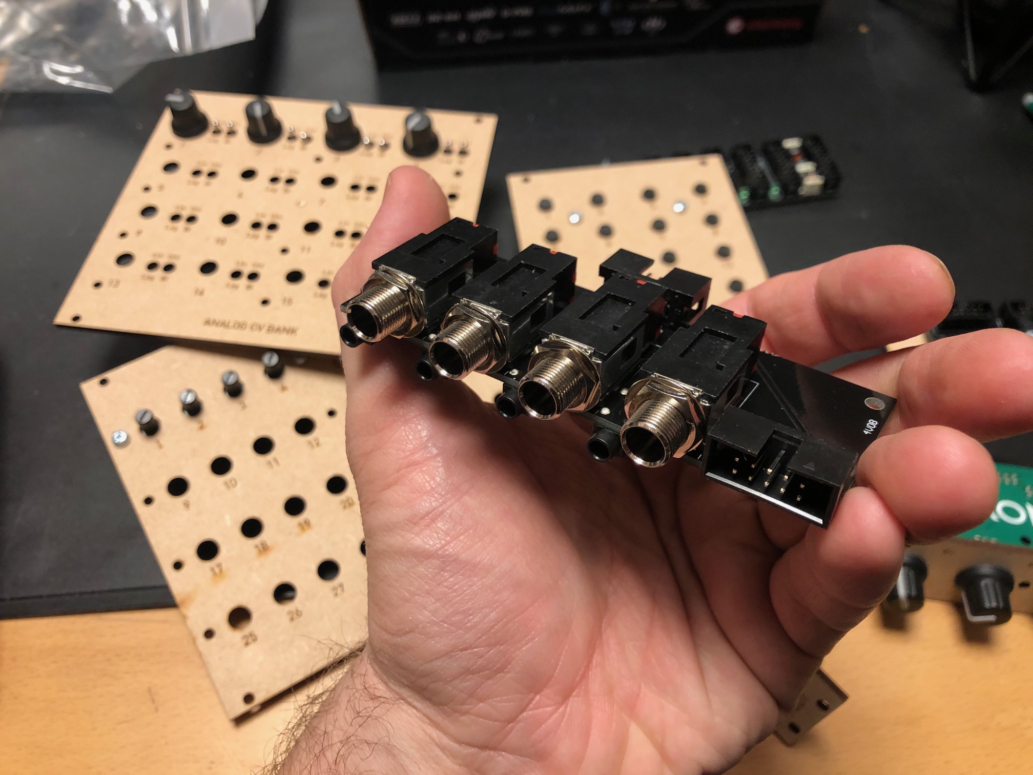
Quad input/output module with 1/4" jacks


For each module you can select input or output connected to the 1/4" jack, and the opposite will be connected to a minijack. Both ends are also connected to a 10p IDC connector for easy connection to a breadboard. For each channel there is an option of 10 or 2 x attenuation and 10 or 2 x gain, meaning you can either have a unity gain circuit, a 5x attenuation (for line out-ish) or 5x gain (for input).


24/48 button module, digital

A digitally scanned button module (without the microcontroller), chainable for up to 48 buttons. Serially read so it only requires four pins + power, making it possible to combine it with the potentiometer module on the same cable.


8 to 64 potentiometers module, digital


A digitally scanned potentiometer module (without the microcontroller). Each module has 8 potentiometers, and 8 modules may be chained for a total of 64 potentiometers. As with the button board, it only requires four pins, and it shares the same clock and reset pins at the button module so a total of six pins + power is needed for all digital modules. During testing I discovered that pin 9 on IC2 - one of the address lines - should have been connected to GND. Now it is floating, so it isn't possible to set the address correctly. It's an easy fix however.


4 x IDC Passthrough module

A simple panel with IDC connectors on both sides, makes it possible to route IDC connectors as a group through the front or back panel without putting the cable through a hole.


Bitcrusher

A combined 12 bit sample rate reducer and bit rate reducer with analog and digital control, based on a PIC16F18446 microcontroller with built-in ADC. Described in separate posts. I've ordered 25 of these.


20kHz LPF

A filter module that can be used as an anti-aliasing filter for ADC input and reconstruction filter for DAC outputs. I use the same configuration in the Bitcrusher and intend to use this for the combined DCO/wavetable oscillators. The circuit comes from this page: https://www.analogfilters.com/anti-aliasing-filter/


Voltage Controlled Distortion

A distortion module for the XM8, the second of the two pre-filter FX (the bitcrusher being the other). Controllable distortion amount and output amplitude, as well as switch between hard and soft distortion. Untested.


Memory


A DIL mounted SMD chip, 128Mbit, for use as sample memory for the wavetable oscillators etc. Untested.


Prophet VS keyboard controller

A new revision of the 68b01 clone for the Prophet VS. I've ordered 20 of these so I have for future sales. They have all been programmed but are missing legs.


Modular synth power bus board

16p Doepfer standard boards with 7 connectors. A bit short but cheap to build.


10p and 16p breadboard IDC connectors

Tiny boards with an IDC connector on one side and legs on the other, making it easy to use ribbon cables between breadboards and modules


Unbuilt designs

In addition, I have PCBs for the following that has NOT been soldered yet:


Breadboard power and I/O module

Has input for +/-15v and a regulator for 5V. Also has IDC connectors for chaining multiple boards, and small chain-boards that can be fitted upside down to connect multiple boards. Connects to the power busses on the breadboard. No more risk of messing up polarities! Also: a 10p Doepfer compatible power connector, although the doepfer uses +/-12V, not 15V, and a 10p I/O connector that connects a ribbon cable to 10 pin headers for easy and stable connections. Pin 10 may be connected to ground with a jumper.


Breadboard coax connector and I/O module

A board with four coax connectors and the same 10p I/O connector as the board above. Will give stable connection points for oscilloscop, function generator and other gear that uses coax.


15-to-12v DC converter module

A module that converts +/-15v from either a molex connector or a 10p IDC connector to +/-12v and +5v. Output is through a 16p connector, compatible with the Doepfer standard. Also has a two pin header for injection of Gate and CV 


All in all 16 different boards! Needless to say, I'm more than pleased! I'm getting so close to being able to test an initial voice board, I just need to program some digital envelopes.


Bonus

I finally got the following soldered and ready for testing:

Two versions of the sample and hold buffer, one with some large caps and some filtering and one in a tiny DIL14 format, both quad sample & hold:


Then the second version of the DCO, this time with DAC output to make it a wavetable oscillator too:


Friday, September 25, 2020

Switches and caps again

 I've been trying hard to figure out a working combination of switches and key caps. I really don't want to use the normal tactile switches that so many old synths use. They wear out over time and the travel is very short.

Where I come from - IT - (and in the rest of the world I guess), mechanical keyboards are all the rage. Incidently, I used Cherry ML switched (and concidered Cherry MX) when I did the Machinebeats drum machine more than 10 years ago, long before Cherry MX became THE keyboard key. I even had a Cherry keyboard in the 90s. But I digress. What I'm saying is I want to use a proper switch, rated for millions of clicks.

The problem is keycaps. While Cherry do/did sell some non-keyboard keycaps, they are still square and keyboard-looking. That's why I want to create my own keycap. But 3D-printing the tiny mounts used for the various switches is not a very good option, especially with a filament based 3D-printer.

My idea is to use a commonly available keycap and mount MY part on top of that. That gives a much bigger surface to glue things to. However, getting a completely flat keycap seems almost impossible.

I'm considering four different switches: Cherry ML, Cherry MX low profile, Kailh Choc and Kailh Choc V2. The MX low profile seems really hard to find, but I've ordered the Kailh variants for testing.

After a few failed attempts, some nice, almost flat Kailh Choc caps arrived from Ali Express today. I immediately tried filing them down using some 180 grit sand paper. And voila! It looks great! The cap height went from 0.13" to 0.12", and now it's completely flat. Great Success! Only issue is the cap is ABS, so I can't laser cut the outline.


I'm still waiting for the switch. I've also ordered some round, flat-looking caps for the Choc V2, but it seems like I have a good option for the Choc so I might as well go with that.

On a separate note - using black keys was a really good idea, it is very easy to see when I have filed it down enough to be flat :-D