Showing posts with label front panel. Show all posts

Sunday, October 5, 2025

UI Progress

I've cleaned up most of the UI now, though it's far from finished. The output and global fx sections will not be completed until the hardware is developed, the same goes for the center console. Still, it's starting to look pretty good.

Right now, the design is strongly inspired by (some would say ripped off from) the Waldorf Quantum Mk I and II, Matrixbrute and Polybrute, with a dash of Moog One and Alesis Andromeda - incidently, all those synths are designed by Axel Hartmann...

Colors are hard though, and even harder when various degrees of shinyness are not visible in my current model. 

Here are some variations:


A Polybrute blue version, with a large black acrylic sheet in the center

 
A more Quantum-esque center display


Slightly darker module color

  
A black with lighter modules version


A version closer to the original Quantum MkI or Matrixbrute, with black modules on a lighter gray background


A more color coded version, dark modules are "audio", mid gray are modulation and light gray are global. Keyboard stuff is now directly on the background

Same as above but more Quantum-esque display again


Introduced vertical separation lines. They don't line up with the clock/route divider which annoys me. It can be fixed by switching osc modulators and note/detune, but that feels wrong too. I like the divider between noise and ring mod though


Added waveform icons


Wednesday, September 24, 2025

Cleaning up the UI

I'm about to make a prototype of the UI, and have been cleaning up the grid a bit. This is what it looks like right now:


Inspired by the Matrixbrute, I started adding boxes around the related parts. The spacings are way off, but it should give some idea as to how things are grouped:


I do have some problems with this though. The vertical slits don't line up, in fact, they make the whole thing look a bit messy. 

I did also make a ready-for-lasercutting mode, that adjusts all line thicknesses and changes pot and button sizes to fit the shafts, ready for prototyping. Here is the left panel again:


 Now, to see if I could do any better, and after looking at the Waldorf Quantum, I came up with the following (crude) version


 It follows a slightly more logical structure, with the sources top left, then the mixer and post-mixer effects. It also groups the LFO and Arp in two separate two-row areas which gives a nice balance. There is not quite enough room for everything, especially the Arp controls, and I've decided to remove the bit crusher level pot as it isn't particularly useful. I do like this quite a bit. 

Then I decided to color the current version too, and to my surprise, I think it looks cleaner than it did with the "real" colors:

I think I can make both versions work. I will prototype the finished version now, and perhaps I'll have time to revisit the second version in the future.

As for the right side - it also needs a bit of cleanup, there is no room for the frame here, and I guess I should redo the filter to work better visually on the 8 row grid if I choose to go with the modified left side. 


I also think I'll probably ditch the post-filter bit crusher as that can be done by a general DSP, and maybe I'll make a smaller group of pots and no screen (or small oled screens?) for the DSP part. I have even been thinking about doing per-voice FX, or at least chorus, though that would mean not using the FX send lines. We'll see.

Monday, September 22, 2025

Pot and button boards tested

I finally got around to testing the potentiometer and button breakout boards yesterday. They seem to work just fine.

Button board with integrated pullups and diodes on top, potentiometer board (six pots per 10p connector) on bottom

breakout board for buttons, making it easier to connect 8 dupont connector buttons to a single 10 connector

While the buttons worked straight away, the pots gave me a bit of a headache. First time around, nothing worked. Turns out, the connection between the potentiometer and the 10p IDC connector is not particularly good. Pushing on the pot made it work, but releasing it made it lose connecton again.

After comparing with the unmounted connectors I have in my drawer, I realised there are two types. One of them has the sprung contacts further out into the hole:


Top: Connectors from the drawer, the contact fills half the hole

Bottom: Connector that failed. The spring fills less of the hole - also, it looks like the edges of the pot legs, being slightly to wide, have dug themselves grooves at the side of the connector, meaning they may not be able to touch the contacts.

Pot inserted into the working connector

Pot inserted into the non-working connector. When pushing the pot down, the legs are pushed up slightly inside the connector, making contact.

pot inserted into the non working connector (slightly more rounded than the working one).


Wednesday, February 26, 2025

Hidden gas struts for lifting the front panel

I need a way to open and close the front panel of the XM8, and also a way of making it stay open. 

I could go the minimoog route and have a fixed bracket that is put in place once open, but perhaps there is a more elegant solution?

What if we could use gas struts/lifts instead?

I found this example on the net:

The only issue I have with that is that the struts are visible when the lid is open.

I've spent the day thinking of a version where the struts are hidden inside the synth instead, and came up with this:

A nice feature, which I guess is also included in the first version, is that once closed the struts won't force the lid open. As long as the direction of the force (green line) is above the hinge/red line, the strut will actually force the lid shut. When opening, once the green line falls below the red line the strut will start pushing the lid open.

Now, I will have to test this in practice to see if I can find a strut that is both powerful enough to keep the lid open and not moving during use, while at the same time not require too much force while closing. Also, since the strut must be angled upwards inside the case, it cannot be very long


Saturday, March 22, 2014

New panels

This week I've finished five new panels and prepared prints for three more. I've done two more oscillator panels, two sub oscillators and one 7-saw controller. I've also printed two more sub oscillators and one controller. Since the edges of the first oscillator panel didn't get as sharp as I wanted when folding the plastic around the edges, I've decided to cut the foil along the edges this time.
Plexi glass panels before attaching the adhesive film

Three oscillator modules - the first one to the left has plastic folded around the edges while the new ones are square cut for a sharper edge. I've also realized that I will run out of orange potmeter caps. Unfortunately, Re'an has stopped producing these so it's hard to get more. I've found some similar looking ones on Ebay, they seem to be 1mm wider but it may work out ok.
Finished sum oscillator and 7-saw control panels

Close-up of the sub oscillator. Note the input polarity switch, setting this to the opposite of the input wave will give that cool saw-within-saw wave shown in an earlier post

Wednesday, January 1, 2014

How to make cheap front panels

Due to our recent car purchase, I expect money to be a bit tighter than usual in the next months. I still need some cool front panels for my upcoming polyphonic/super saw synth. I have therefore been looking for ways to create decent panels at a low price instead of using Schaeffer/front panel express or similar services.

Today I completed the first prototype, a panel for the 8-saw oscillator, and this post explains the process in detail.

I have the luxury of co-owning a Silhouette Cameo cutter with my wife. This machine, while meant for scrapbooking and cutting vinyl for arts & crafts, works perfectly for cutting all sorts of soft materials. While you can get away with just an x-acto knife or similar, the machine makes the job so much easier and the end result much better.

Requirements

For the panels, you need the following:
- 2 mm thick perspex/plexiglass or similar hard plastic glass
- Adhesive-backed glossy photo paper
- Adhesive-backed transparent plastic

I got my perspex from Biltema here in Norway, but you can get similar stuff elsewhere. Make sure it is 2 mm, any more and you may not be able to attach the mini jack sockets, any less and the panel will bend too easily.

The photo paper I used is called Skyhorse Premium Quality Glossy Photo Paper, 130g, self-adhesive cast-coated. I got it off ebay in the UK. It is rather thick, and the ink I use (Canon CLI-55xx) is not absorbed well enough to protect it from wear and tear - it smudges easily even after drying for some time. This is however no problem as long as the paper is covered with the adhesive transparent plastic

The adhesive plastic I use is the kind used as a dust cover on books. It comes in glossy and matte finish, I've chosen the glossy one.

The process

Perspex

First I designed the panel in Illustrator. When doing this, I added cross hairs to all circular components, to tell me where to drill holes. When satisfied with the design, I made a copy of it and removed all but the outline and cross hairs. I then printed this design onto a piece of the adhesive photo paper, trimmed the edges using a paper cutter and attached it to the perspex. To make it easy to remove after drilling, I put the paper on top of the protective film that covered the perspex.

I then drilled all holes using a 1 mm drill bit in a drill press. It's much easier to get an accurately positioned hole using such a small bit first. Remember to also drill holes for any key tabs on the potentiometers.

Some of my holes are very close (1 mm) to the edge of the perspex. I drilled these first, in case they crack the perspex, so that as little work as possible is lost. Be very gentle and do not put a lot of pressure on the drill.

I then drilled 3 mm holes, even in those places where the end hole is supposed to be larger than that - still to get a better accuracy.

Then I used a conical drill bit to drill any holes larger than 10 mm. Finally, I drilled any remaining 6 and 7 mm holes.

After drilling all the holes I used a scroll saw to cut the edges and straightened them by sliding the panel along a metal file. This is the end result:

Cut and drilled perspex
Note that I tried to drill the holes for the potentiometer key tab only partially through the perspex. This was a bad decision as the plastic extrudes slightly, making the hole visible on the front even after attaching the photo paper. Had I drilled it all the way through, it would probably have been invisible.

Photo paper

After creating the raw perspex panel, I printed the panel design onto the adhesive photo paper.

The Silhouette cameo comes with a plugin for Illustrator that lets you add what is called registration marks to your drawing. Later, when you want to cut out parts of the design (holes for pots etc), the Cameo recognizes these registration marks and knows where the design is located on the paper. The plugin costs $40 but is well worth the money.

Panel design with registration marks in the corners
Next up is to cover the panel with the transparent plastic to increase its durability. I decided I wanted the edges to be well protected as well, so I came up with a way that let me put the plastic around the edges and onto the back. If you do not need this, just put plastic all over the panel and cut along the edges of the front panel (after creating holes for the pots etc).

In my case, I had to cut away parts of the photo paper around the edges of the panel so that the plastic film would not stick there. As the photo paper already has a non-stick backing paper, you only need to remove the photo paper itself. However, it is hard to cut through the top layer only, so I did instead cut all the way through:
Cut two grooves about 10 mm apart.
After cutting two grooves, I turned the paper over and put some Scotch magic tape over it to keep it in place. I then did the next side the same way etc:


Finally, I removed the photo paper from the parts I had cut out:


I could now cover the whole paper with plastic film:


 After covering the paper, I attached it to the cutting mat of the Silhouette Cameo:


Based on the same Illustrator design, I created outlines for the potmeter holes etc in the same position as the previously created cross hairs. I made sure to make the holes about 1 mm larger that the holes I drilled, as the silhouette is not accurate enough to get a perfect hit. The design is then sent to the machine and "printed" onto the panel. Due to the thickness of the plastic and paper combined, I had to set the cutting knife to 8, and even this proved to be a bit too little in some cases. Ideally you want to cut all the way through the photo paper but not through the backing paper.
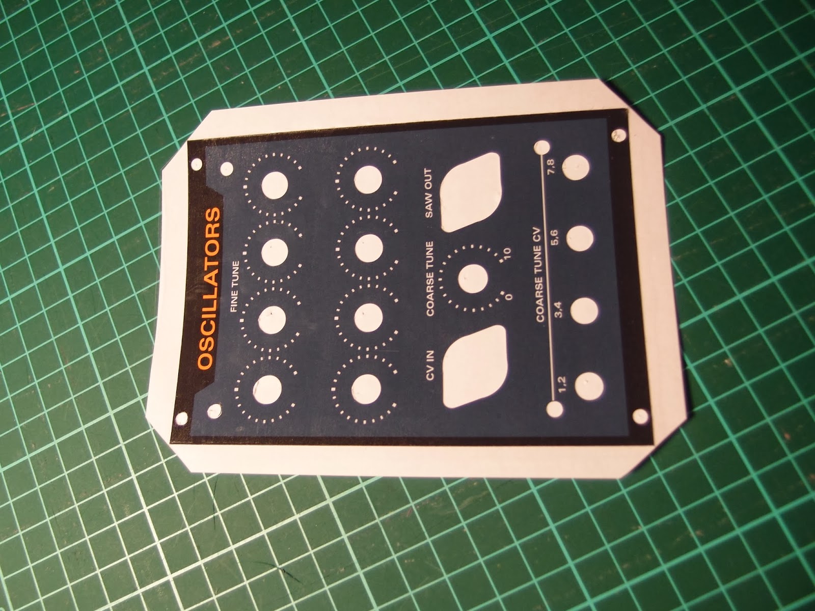

I now carefully removed all the cut out parts using a sharp hook


Then I cut off the edges using a paper cutter. The corners are cut diagonally to be able to wrap them around the edges


Finally, I removed the panel from the backing paper and attached it to the perspex


After attaching the front panel components (knobs, jacks etc), all edges are covered and the result is quite pleasing. The plastic is slipping slightly from the photo paper close to the edges, this will probably not happen if you do not fold the plastic around to the back. Also, when tightening the DIN-jack sockets the plastic bulges slightly, this can possibly be prevented by cutting the plastic closer to the screw holes.


All in all I think the result is very good, especially considering the price and the time it took to create it.