Showing posts with label switch. Show all posts

Monday, September 22, 2025

Pot and button boards tested

I finally got around to testing the potentiometer and button breakout boards yesterday. They seem to work just fine.

Button board with integrated pullups and diodes on top, potentiometer board (six pots per 10p connector) on bottom

breakout board for buttons, making it easier to connect 8 dupont connector buttons to a single 10 connector

While the buttons worked straight away, the pots gave me a bit of a headache. First time around, nothing worked. Turns out, the connection between the potentiometer and the 10p IDC connector is not particularly good. Pushing on the pot made it work, but releasing it made it lose connecton again.

After comparing with the unmounted connectors I have in my drawer, I realised there are two types. One of them has the sprung contacts further out into the hole:


Top: Connectors from the drawer, the contact fills half the hole

Bottom: Connector that failed. The spring fills less of the hole - also, it looks like the edges of the pot legs, being slightly to wide, have dug themselves grooves at the side of the connector, meaning they may not be able to touch the contacts.

Pot inserted into the working connector

Pot inserted into the non-working connector. When pushing the pot down, the legs are pushed up slightly inside the connector, making contact.

pot inserted into the non working connector (slightly more rounded than the working one).


Monday, August 7, 2023

CMOS switches and current switching

After my previous post where I discovered that Douglas Self has some examples where he's switching mixer inputs at the op amp virtual ground, and after talking to the guy on Reddit that made me discover the CH446Q (ARabidSquid, Architeuthis Flux on Tindie), I decided to test it in practice.

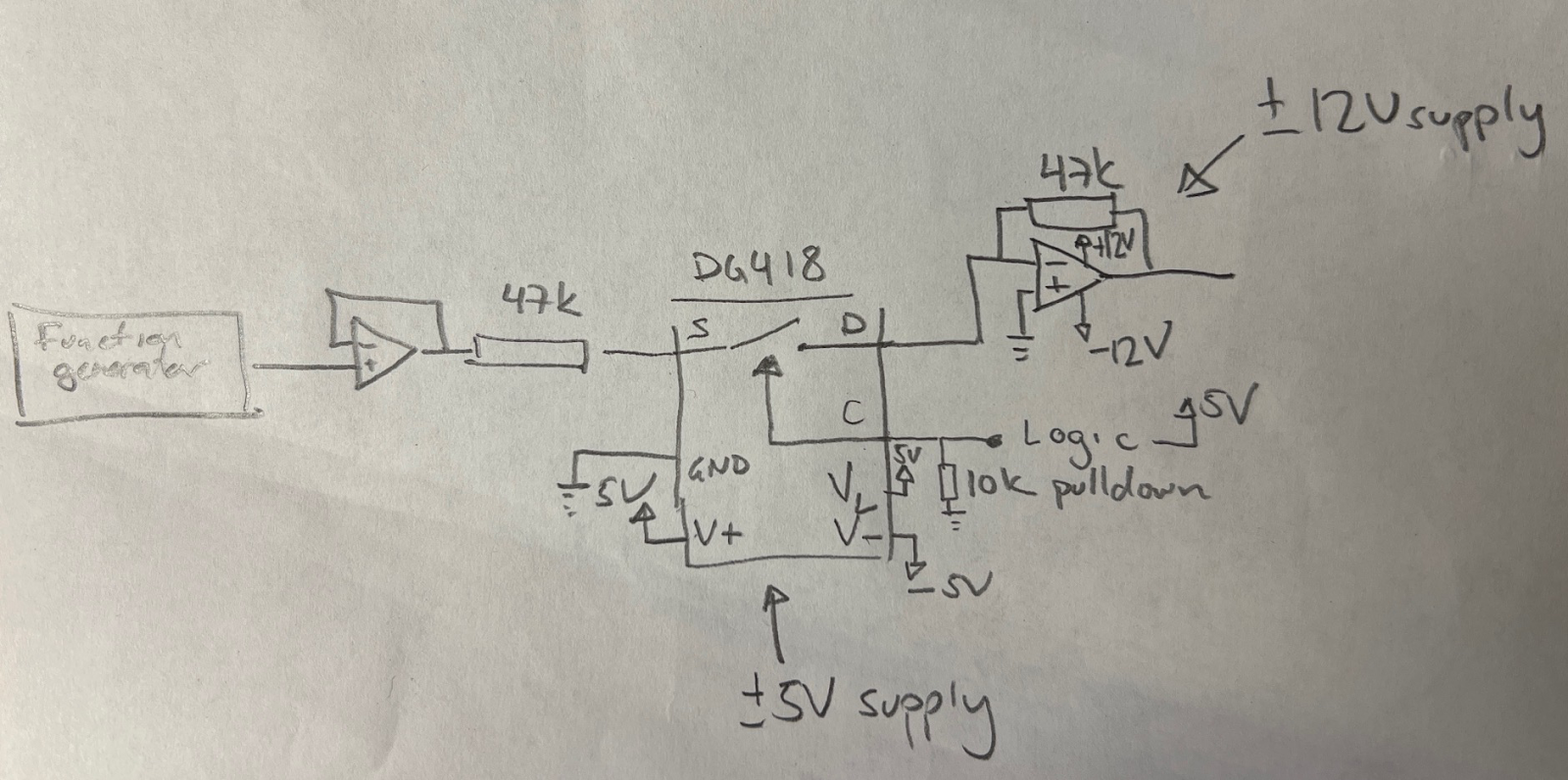
I hooked up a DG418 on a breadboard, and used an 78L05 and 79L05 to get a +/-5V supply for the DG418.

I then used a TL072 op amp with +/-12V supplies, with one op amp to buffer the input from the function generator and the second to "sum" (just invert really) the output from the switch, with a 47k negative feedback resistor. 

Version of circuit where input resistor is before the switch


I could now experiment with having the op amp input resistor BEFORE the switch (placing the switch at the virtual ground) or AFTER the switch

An initial test with a 10Vpp (+/-5V) signal showed that it worked in both configurations.

Resistor after the switch, 10Vpp

Resistor before the switch, 10Vpp


I then placed a 20Vpp signal on the version with the resistor after the switch. As expected, the switch clips the signal since it sees the full 20Vpp, but exactly how it clips is interesting. Measured at the input pin (i.e. the output of the buffer), the INPUT is clipped - the top is at 9.16V and the bottom at -5.85. I didn't expect it to be asymmetrical.

Resistor after the switch, 20Vpp. Output (and input) clips


Next up, I moved the resistor to before the input. The switch should now see no voltage swing (though a current passes through, +/-0.2mV at its peaks). This also worked as expected, the output is also 20Vpp (though inverted because of the op amp configuration).

Resistor before switch, 20Vpp passes nicely


This looked very promising. Next up was turning the switch OFF. 

Again, for the 10Vpp signal, it worked as it should for both variations.

Switch off, 10Vpp


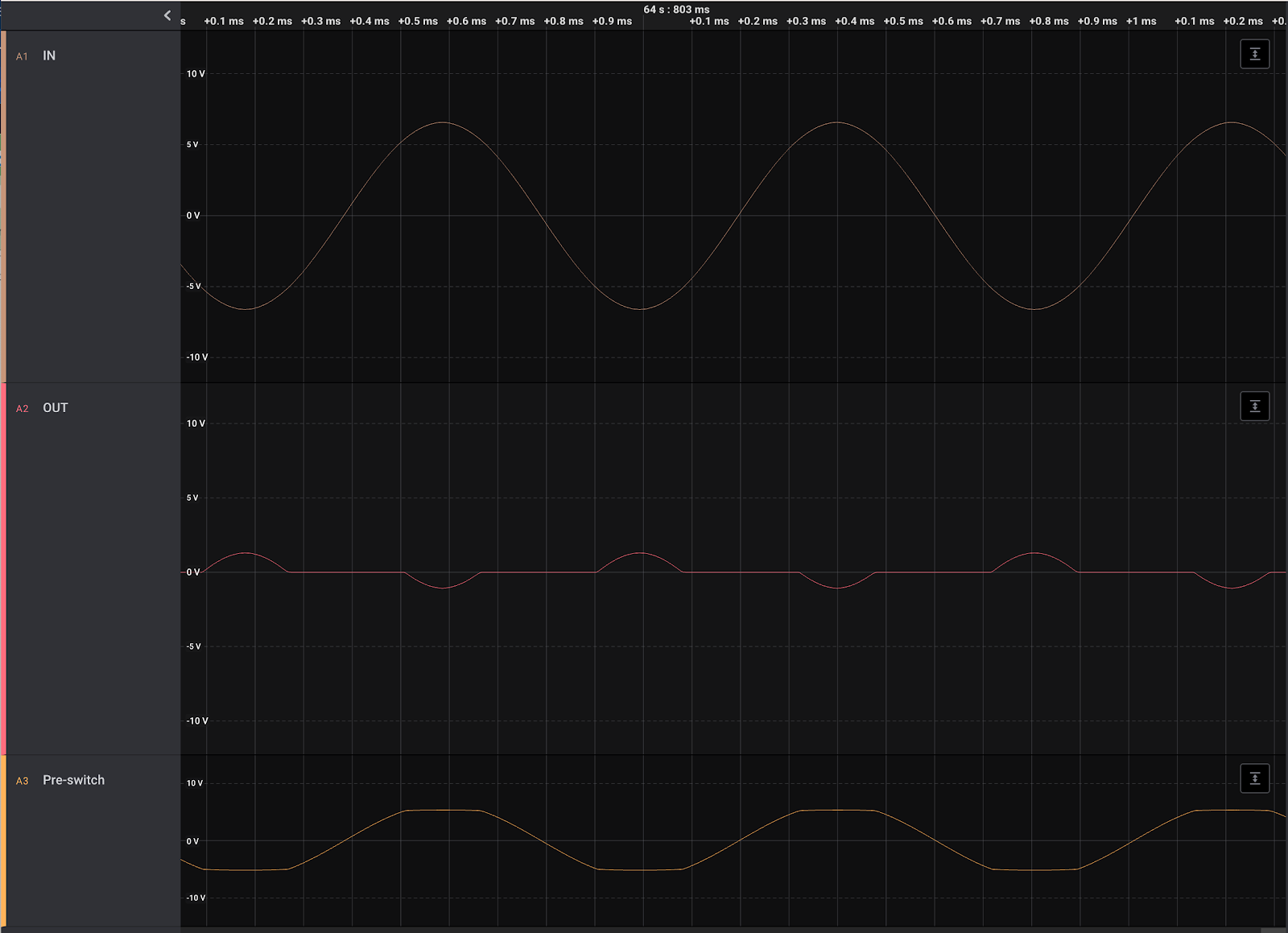
I then tried cranking up the signal for the variation with the resistor before the switch, but then "disaster" struck: Once the input signal got higher than the DG418's supplies, it started leaking! With a 13Vpp input, it blocked everything up to 10Vpp. The remaining, however, was passed through, giving the output small "bumps"! 

Resistor before switch, switch off, 13Vpp. Anything above approx 5.1V is passed, giving funny little bumps on the output.


When showing the result to ARabidSquid, he confirmed that this was how CMOS operate, it cannot block anything higher than it's supply voltages.

After seeing this result, I remembered that I read something similar yesterday - someone posted about a similar issue, where a current input made the switch leak when it was turned on. Someone suggested using an SPDT (or two switches in a crosspoint switch) to sink the current. This could be an option, to use a separate bus to sink all input signals that are not in use. However, I think I'd rather stay within the operating limits and keep my signals at 16Vpp max.

Friday, November 6, 2020

Shanpu switches

 I got a shipment of sample switches from Shanpu in Taipei today. I had to pay full DHL express freight but they were very nice and sent me the samples for free. I will be able to buy directly from them in multiples of 100 of each item, and the price ends up at around $1.4 per switch including cap, but shipping and a rather steep low-volume fee of $100 for orders below 1000 means the real cost is closer to $3-4 depending on the number of switches I buy.

There are several switches to choose from. All are rated at 1,000,000 cycles!

The SPH2S has an audible click and a short travel of 0.2 to 0.3mm, 190 +/- 50gf force

The SPH2T has a very audible click and a medium long travel of 0.4 to 0.6mm, 230 +/- 50gf

The SPH2N has a no audible click and a very long travel of 1.0 to 1.4mm, 60 +/- 40gf


Then there is a low profile version, but it is only rated for 100,000 cycles, so unless it is more suitable due to the low profile, I should really go for one of the others.

The SPFSP1 has an audible click and a short travel of 0.2 to 0.4mm, 200 +/- 50gf force


In some ways I like the N version best, it sits somewhere between the keyboard switch feel of the Nord keyboards and the normal clicky synth button. It doesn't feel quite right somehow though, it's like the travel is a bit too short or something.

The T is a bit too noisy for me, so that leaves me with the S. The click feel of the S is closest to the D50 when comparing to some of my synths. It is a little bit on the heavy side though, switching between it and the N makes me think I like the feel of the N better.


But then there is another issue - caps.

I ordered six different caps in four different designs

YCA085C, a 9.6mm round, transparent black cap with a "lense" effect on top. It turns out that it is glossy, and because of the way it has been made, with a hole in the center, the light is rather uneven. Not too much, but it is not the best.

YCA151A, same as YCA085C, but one mm shorter and Ice color (translucent white). The light is much better, but this may simply be because more light gets through due to the color, or it is because it is 1mm shorter. I have to retest the black one with a smaller diode. Of course, its white when switched off, so it will not blend into the design if I choose a black front panel.

YCA080C, an 8mm round transparent black cap. It has a more frosted look and is flat on top. It looks really great and the light is much better too. It has ONE major drawback though, and that is that it's only 3.3mm long. If I use a 3mm panel, or a long travel switch, it is simply too small for me. It's really a shame, because it's hands down the winner when it comes to looks. Oh, and it would be a perfect match for the 8mm black alu 

YCA059C, an oval transparent black. It is too small for my liking.

YCA044A, a square, 7.5mm ice white cap with a slightly rounded top. It looks good, but is too thin, and the led is clearly visible through, so I can't use it.

YCA043C, a square, 7.5mm transparent black cap with flat top. Unfortunately it is simply too transparent and completely useless. It WOULD however make a perfect base for glueing the black 8mm alu caps on top of, if I want to use them with the same switches. I may even use them for the red square Aliexpress caps.

Bonus test: The red square aliexpress caps look ok with the led, though they have an internal pattern that is very visible. It doesn't really look like they are meant to be backlit.

That means that I'm probably down to two options: The biggest round transparent black cap with whatever switch I like the best, or the 8mm round cap with the S-model switch and a thinner panel. I must test if I can get away with 2mm aluminum.


Update:

1 - There is an even better option for attaching aluminum caps: They sell a 5mm round cap, YCA052, which probably will fit very well inside the aluminum - perhaps with a 1mm gap that could possibly be filled with glue? There is also a 6mm one, YCA046. Perhaps I should buy both just to check. BTW: The top of the alu cap may be too thick for this option, but the extra cost of buying 100 caps is so little that it would be stupid not to do so.

2 - For the switches where the led will NOT be used, it would be possible to put a piece of black cardboard inside and coloring the edges of the cap holder black to get a much darker cap - the white parts shine through and making the insides black helped a lot.

3 - changing from a 270Ohm to a 150Ohm for the thicker transparent black cap helps. Still not as good as the other though, so I definitely have to test 2mm aluminum panels.

Friday, September 25, 2020

Switches and caps again

 I've been trying hard to figure out a working combination of switches and key caps. I really don't want to use the normal tactile switches that so many old synths use. They wear out over time and the travel is very short.

Where I come from - IT - (and in the rest of the world I guess), mechanical keyboards are all the rage. Incidently, I used Cherry ML switched (and concidered Cherry MX) when I did the Machinebeats drum machine more than 10 years ago, long before Cherry MX became THE keyboard key. I even had a Cherry keyboard in the 90s. But I digress. What I'm saying is I want to use a proper switch, rated for millions of clicks.

The problem is keycaps. While Cherry do/did sell some non-keyboard keycaps, they are still square and keyboard-looking. That's why I want to create my own keycap. But 3D-printing the tiny mounts used for the various switches is not a very good option, especially with a filament based 3D-printer.

My idea is to use a commonly available keycap and mount MY part on top of that. That gives a much bigger surface to glue things to. However, getting a completely flat keycap seems almost impossible.

I'm considering four different switches: Cherry ML, Cherry MX low profile, Kailh Choc and Kailh Choc V2. The MX low profile seems really hard to find, but I've ordered the Kailh variants for testing.

After a few failed attempts, some nice, almost flat Kailh Choc caps arrived from Ali Express today. I immediately tried filing them down using some 180 grit sand paper. And voila! It looks great! The cap height went from 0.13" to 0.12", and now it's completely flat. Great Success! Only issue is the cap is ABS, so I can't laser cut the outline.


I'm still waiting for the switch. I've also ordered some round, flat-looking caps for the Choc V2, but it seems like I have a good option for the Choc so I might as well go with that.

On a separate note - using black keys was a really good idea, it is very easy to see when I have filed it down enough to be flat :-D