Showing posts with label oscillator. Show all posts

Tuesday, July 21, 2026

Digital oscillators on the XM8

After deciding on creating a wavetable oscillator for the XM8, I've thought quite a bit about the digital oscillator structure. Here is my current solution


Two physical DACs

First of all, I will add a new PCM5102 I2S stereo DAC. This has built-in oversampling etc to prevent aliasing-noise. However, in old synths there were a lot of aliasing, which is part of what we now recognize as the vintage sound. I don't think the PCM5102 can recreate this.

However, my initial idea was to use the DAC8830 on the DCO boards for wave duties as well, and have the DCO MCU do the heavy lifting when it comes to wavetable morphing and other interpolation. The DCO DAC was then followed by an analog reconstruction filter.


The DCO as a DAC proxy

I now have a new idea. Let's instead use the DCO MCU as a simple DAC proxy. By copying the incoming SPI signal to the output whenever the DCO is in "direct to DAC" mode, the MCU doesn't have to do any work. We could probably speed up the SPI bus to max and easily get 44.1kHz (or 48kHz) sample rate on the DAC. The only thing left to solve is when to interpret the DCO incoming data as bytes directly for the DAC - we could increase bit length to 24 and use the first as command, but perhaps that makes it harder to use Teensy Audio. It should be possible to use custom SPI DACs with Teensy audio so let's hope this works. If not, there is still an available utility pin on the DCO that can be used for mode switching.

We would also have to send the chip select for the DAC, but only after two received bytes, not 1 as on the PIC16F SPI.

We can also get rid of the recon filter, after all the only reason we do it this way is to get the aliasing. Also, it would be possible to reduce the bit depth to 12bit if we want etc.


DAC routing

The analog board already has an input for digital waves per DAC, and a switch to select between that and the waveshaper output.

We can reuse that - and in place of the current reconstruction filter, we'll put a second switch selecting either PCM5102 or DAC8830. We also need the circuit to center and amplify the output from the DAC8830. Currently it's at 0 to 3v3. Finally, we need two available pins on the Teensy for controlling the switch.


Modifying the v1.0 Digital voice controller 

This requires the use of two additional pins on the recon filter socket - one for the PCM5102 input and one from the Teensy to control the switch. We should also cut the paths from the PCM5102 to the ext input (cut on the digital voice card side).


Summary

It will be possible to use one of three modes per oscillator: DCO, high quality audio DAC or aliasing basic DAC. It won't be possible to combine DCO with the other two at the same time on the same oscillator. I think this is a fair limitation that makes operation of the oscillators simpler - what you see is what you get, if you switch oscillator mode you also switch its output.


Sunday, June 28, 2026

Wavetable oscillator

I need a more precise sine wave than I have at the moment, with a larger range than I can get from the DCO.

That gave me an excuse to go ahead and create the wavetable/PCM oscillator I've been thinking about - there's a slot on the digital board exactly for this.

My colleague Alexander used a PCM5102A DAC for his project, and after taking a closer look it seems this was the ideal choice for my oscillator as well. Even better, I realised I had a breakout board with that DAC already, from Aliexpress, so I could go right ahead and test it!

Here is my layout:

CLK: GND

BCLK: Teensy pin 21

LRCLK: Teensy pin 20

DATA: Teensy pin 7


NB: All data/clock pins have a 22Ohm resistor on them to slightly slow down the edges. This is both suggested by the teensy communit (100Ohm) and the breakout board (22Ohm). 

The rest of the configuration pins are already taken care of on the breakout board, but in any case they are:


DEMP: GND (Deemphasis off)

XSMT: +Vpp (Soft mute: un-muted)

FMT: GND (I2S)

FLT: GND (normal latency) - I've made this configurable in my circuit


For the rest of the pins, see my schematic: 

I've added two inverting gain op amps that brings the output up to +/-5V. FLT (filter latency) is configurable and can also be disconnected from the control pin by cutting the solder jumper.


 I've already implemented wavetable morphing, through any number of wavetables. I've added the four basic waveforms (sine/tri/saw/square) and converted the Prophet VS wavetables into a format that I can use. It sounds amazing!

Right now the oscillators are routed through the ext pot. I originally intended wavetable oscillator duty to be performed by the DCO circuits, so there's a switch between DCO and waveform after the waveshaper on the analog board.

Now I'm not so sure anymore. It would be nice to not use the ext route. Instead, wavetable-osc could be routed directly to the mixer, and to have separate volume control per osc. Instead of having one channel per wavetable oscillator I could let one channel go to each of the busses. I can mix the oscillators digitally instead, and have digital volume control of them.

This is much more flexible. I can use both DCOs and WT at the same time, or I can make them mutually exclusive in software. The only issue is that DCO and WT have to share the same panel pot, meaning we no longer get knob-per-function if both DCO and WT are available at the same time. Then again, this could also be configurable... 

Sunday, July 19, 2020

Oscillator UI

Just an initial sketch, let user morph between waveforms, and select what waveforms should be included in the morph:

By selecting only certain waveforms for morphing means one can start a morph by a modulation source at a different point than sine.

How to select various stuff for modulation by various sources needs to be investigated.

Monday, March 23, 2020

VCO and DCO boards

DCO and VCO boards, both made to fit in 28 pin DIL wide (600 mil) sockets

First, a CEM3340 board with hard sync and almost all necessary components onboard. Outputs +/-5v waves. Because of the uncertainty of whether or not there are issues with detuning when using the built in CEM3340 pulse, I have added an external pulse generator.


My previous DCO design, adapted for DIL28. has a different MCU and DAC than what I used previously as those weren't available at JLCPCB.


Sunday, January 29, 2017

DCO

I've started working on a DCO circuit, as this will probably require fewer (but perhaps more expensive) parts and be easier to tune.

I want the DCO to work for all midi notes (C0-B8) and be within 1 to 3 cents of the correct frequency for all notes.

Looking at the Juno 6/60/106 and JX-3P DCOs I've so far set up a google docs spreadsheet, calculating all periods to get correct frequencies and the necessary voltages (currents) to get a constant amplitude.

A short intro to DCO theory

DCOs are (often) based around a relaxation oscillator, exactly like a saw core VCO (http://xonik.no/theory/vco/reference_current.html - this also explains how the capacitor is charged). A current charges a capacitor and a transistor short circuits and discharges it to restart the period.

DCOs are stable because they use a digital timer to control the discharging of a capacitor instead of relying on an accurate charging current - the period and thus frequency is computer controlled and highly accurate. For the saw ramp to reach the same amplitude as the charging period (time available to charge the capacitor during a cycle) changes, the DCO instead changes the charging current. As the frequency changes exponentially with rising notes, so must the charging current.

In my spreadsheet I have calculated two important aspects for a physical circuit - the accuracy of the timer generating the period/frequency and the accuracy of the charging current generation.

Frequency

A microcontroller timer has two properties - the minimum period and the maximum count. These limits the length of an output period and the accuracy of its length. A 16bit timer can at most count to 65535 and has a maximum accuracy of +/- 0.5 times its minimum period. For example, if the timer frequency is 8MHz, each tick of the timer is 0.125uS and the accuracy is thus +/-0.0625uS. Its maximum output period length is 65536 * 0.125uS = 8192uS or 8.19mS. The consequency is that a 16 bit timer running at 8MHz has a minimum output frequency of 1/8192uS = 122Hz. (Here we assume that the timer restarts the period whenever it has counted to its maximum).

The accuracy limitation is most important to the upper end of the frequency range. The maximum needed frequency (B8 = 7902,13282Hz) has a period of 126,55uS. An inaccuracy of 0.0625 equals an error of about 0.05%. The human ear is able to hear a difference between two notes played after eachother of about 10 cents/0.6% if the notes are sine waves, less if they are complex tones. Thus, this inaccuracy is well within what is acceptable.

But what can we do to make the timer count long enough for deeper notes? We can either use a bigger timer (32bit) or more often, use a prescaler that divides the clock running the timer. If we use a prescaler of 2, the timer frequency changes from 8MHz to 4MHz, the minimum period changes from 0.125uS to 0.25uS and the maximum time from 8.19mS to 16.38mS. This makes the lowest possible frequency 61Hz. Changing the prescaler to 8 gives a minimum frequency of 15.25Hz, which is low enough for C0.

Unfortunately, increasing the prescaler also decreases the accuracy as the minimum period gets longer. I have set 3 cents as the maximum error acceptable at the highest frequency. Using a prescaler of 8 makes some of the notes at the top of the frequency range fall outside the target accuracy.

In short - using a 16bit timer, we cannot use a single prescaler value and achieve both the frequency range and the accuracy needed. To solve this, we need to change the prescaler somewhere towards the lower end of the frequency scale. To get a constant time used setting up the timer, i propose always setting the prescaler when reloading the timer.

Amplitude

DCOs use different ways of creating a control current. As mentioned previously, the necessary charging current changes exponentially as the notes change. The Juno 6/60 seems to use an exponential converter (I may be wrong about this though, I haven't studied it closely) to achieve this, but such a converter has the same temperature dependency problems as the one controlling the pitch in a VCO (but the effect in the DCO is on the amplitude, not the pitch, and will thus not be as noticeable).

The Juno 106 and JX-3P however just feed the output of a DAC through a resistor and into the integrator (saw ramp generator). This means that the DAC must generate a voltage that accurately approximates the exponential curve needed throughout the note range (the voltage is converted to a current through a resistor). This may be problematic as the rate of change is very small at one end then suddely very large at the other.

I've once again used the spreadsheet to calculate first the real the charging voltage needed, then the current created using a DAC of arbitrary resolution. By rounding off the needed current to the nearest value achievable with the DAC, then multiplying with the per-step voltage, then using the capacitor charging formula with the known period as t, we will find the real amplitude of the wave and thus the maximum error per note.

Using a 16bit DAC and charging a 1nF capacitor through a 100k resistor, we are able to charge the capacitor to within 0.02V (of a maximum of 5V), or 0.4% of the wanted amplitude for all notes.

When calculating the capacitor charging, I've assumed that we can follow the same formula as in my older VCO research, where I found that the voltage across the capacitor at a time t after the charging starts, V(t) = t * I/C. I is found by dividing the DAC voltage Vdac with the input resistor R. Rearranging for Vdac gives us Vdac = V(t) * C * R / t, and to calculate the resulting max charging voltage, V(t_max) = Vdac * t_max / C * R.

My calculations can be found here: https://docs.google.com/spreadsheets/d/1ROhU0L4UZ2CWLu3h5LHopaB0Jv7ewNRziecj5I6D27M/pub?gid=0&single=true&output=pdf

Further work:
- Figure out how to calculate timer values and dac settings (lookup tables?)
- How to interpolate efficiently between values in the lookup table to reduce its size while still allowing input pitch to be a 16 bit value
- How to do DCO sync
- Possibly: Changing timer/charge voltage in the middle of a cycle in order for the DCO to respond instantly (the Juno DCOs apparently only change pitch at the start of a cycle.

Saturday, March 22, 2014

New panels

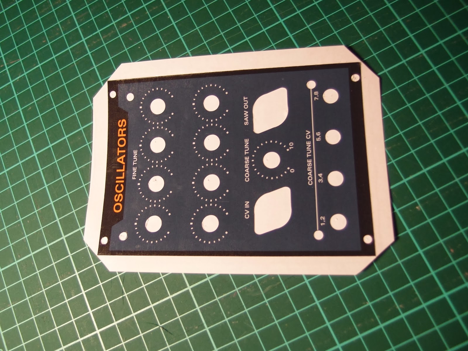
This week I've finished five new panels and prepared prints for three more. I've done two more oscillator panels, two sub oscillators and one 7-saw controller. I've also printed two more sub oscillators and one controller. Since the edges of the first oscillator panel didn't get as sharp as I wanted when folding the plastic around the edges, I've decided to cut the foil along the edges this time.
Plexi glass panels before attaching the adhesive film

Three oscillator modules - the first one to the left has plastic folded around the edges while the new ones are square cut for a sharper edge. I've also realized that I will run out of orange potmeter caps. Unfortunately, Re'an has stopped producing these so it's hard to get more. I've found some similar looking ones on Ebay, they seem to be 1mm wider but it may work out ok.
Finished sum oscillator and 7-saw control panels

Close-up of the sub oscillator. Note the input polarity switch, setting this to the opposite of the input wave will give that cool saw-within-saw wave shown in an earlier post

Sunday, January 5, 2014

Quad saw mixing

Before new years I tried hooking up a simple mixer to mix four saw waves. The mixer consisted of half of a TL072 and five 47k resisors.

While I DID get a mixed output, it sounded worse for every new oscillator I connected. Today I hooked up an oscilloscope to try to see if I could figure out what was going on, and in fact I quickly realized the problem.

When mixing two +/- 5V signals with unity gain, they will occasionally reach +/10V. Mixing three oscillators will result in +/-15V, and four results in +/-20V. The problem is of course that above 14.8V (or thereabouts), the op amp starts clipping, chopping of the tops. This does not sound very nice at all.

By reducing the gain resistor to 12k, the sum of the four oscillators will be within the original +/-5V. And indeed, the output sounds so much better! Now I'm closing in on the buzzing, swarming multi-saw sound I am looking for :-)

I have to rethink the oscillator mixer for the 7-saw though, to prevent clipping at all times. Next up is breadboarding the mixer again :-D

Wednesday, January 1, 2014

How to make cheap front panels

Due to our recent car purchase, I expect money to be a bit tighter than usual in the next months. I still need some cool front panels for my upcoming polyphonic/super saw synth. I have therefore been looking for ways to create decent panels at a low price instead of using Schaeffer/front panel express or similar services.

Today I completed the first prototype, a panel for the 8-saw oscillator, and this post explains the process in detail.

I have the luxury of co-owning a Silhouette Cameo cutter with my wife. This machine, while meant for scrapbooking and cutting vinyl for arts & crafts, works perfectly for cutting all sorts of soft materials. While you can get away with just an x-acto knife or similar, the machine makes the job so much easier and the end result much better.

Requirements

For the panels, you need the following:
- 2 mm thick perspex/plexiglass or similar hard plastic glass
- Adhesive-backed glossy photo paper
- Adhesive-backed transparent plastic

I got my perspex from Biltema here in Norway, but you can get similar stuff elsewhere. Make sure it is 2 mm, any more and you may not be able to attach the mini jack sockets, any less and the panel will bend too easily.

The photo paper I used is called Skyhorse Premium Quality Glossy Photo Paper, 130g, self-adhesive cast-coated. I got it off ebay in the UK. It is rather thick, and the ink I use (Canon CLI-55xx) is not absorbed well enough to protect it from wear and tear - it smudges easily even after drying for some time. This is however no problem as long as the paper is covered with the adhesive transparent plastic

The adhesive plastic I use is the kind used as a dust cover on books. It comes in glossy and matte finish, I've chosen the glossy one.

The process

Perspex

First I designed the panel in Illustrator. When doing this, I added cross hairs to all circular components, to tell me where to drill holes. When satisfied with the design, I made a copy of it and removed all but the outline and cross hairs. I then printed this design onto a piece of the adhesive photo paper, trimmed the edges using a paper cutter and attached it to the perspex. To make it easy to remove after drilling, I put the paper on top of the protective film that covered the perspex.

I then drilled all holes using a 1 mm drill bit in a drill press. It's much easier to get an accurately positioned hole using such a small bit first. Remember to also drill holes for any key tabs on the potentiometers.

Some of my holes are very close (1 mm) to the edge of the perspex. I drilled these first, in case they crack the perspex, so that as little work as possible is lost. Be very gentle and do not put a lot of pressure on the drill.

I then drilled 3 mm holes, even in those places where the end hole is supposed to be larger than that - still to get a better accuracy.

Then I used a conical drill bit to drill any holes larger than 10 mm. Finally, I drilled any remaining 6 and 7 mm holes.

After drilling all the holes I used a scroll saw to cut the edges and straightened them by sliding the panel along a metal file. This is the end result:

Cut and drilled perspex
Note that I tried to drill the holes for the potentiometer key tab only partially through the perspex. This was a bad decision as the plastic extrudes slightly, making the hole visible on the front even after attaching the photo paper. Had I drilled it all the way through, it would probably have been invisible.

Photo paper

After creating the raw perspex panel, I printed the panel design onto the adhesive photo paper.

The Silhouette cameo comes with a plugin for Illustrator that lets you add what is called registration marks to your drawing. Later, when you want to cut out parts of the design (holes for pots etc), the Cameo recognizes these registration marks and knows where the design is located on the paper. The plugin costs $40 but is well worth the money.

Panel design with registration marks in the corners
Next up is to cover the panel with the transparent plastic to increase its durability. I decided I wanted the edges to be well protected as well, so I came up with a way that let me put the plastic around the edges and onto the back. If you do not need this, just put plastic all over the panel and cut along the edges of the front panel (after creating holes for the pots etc).

In my case, I had to cut away parts of the photo paper around the edges of the panel so that the plastic film would not stick there. As the photo paper already has a non-stick backing paper, you only need to remove the photo paper itself. However, it is hard to cut through the top layer only, so I did instead cut all the way through:
Cut two grooves about 10 mm apart.
After cutting two grooves, I turned the paper over and put some Scotch magic tape over it to keep it in place. I then did the next side the same way etc:


Finally, I removed the photo paper from the parts I had cut out:


I could now cover the whole paper with plastic film:


 After covering the paper, I attached it to the cutting mat of the Silhouette Cameo:


Based on the same Illustrator design, I created outlines for the potmeter holes etc in the same position as the previously created cross hairs. I made sure to make the holes about 1 mm larger that the holes I drilled, as the silhouette is not accurate enough to get a perfect hit. The design is then sent to the machine and "printed" onto the panel. Due to the thickness of the plastic and paper combined, I had to set the cutting knife to 8, and even this proved to be a bit too little in some cases. Ideally you want to cut all the way through the photo paper but not through the backing paper.


I now carefully removed all the cut out parts using a sharp hook


Then I cut off the edges using a paper cutter. The corners are cut diagonally to be able to wrap them around the edges


Finally, I removed the panel from the backing paper and attached it to the perspex


After attaching the front panel components (knobs, jacks etc), all edges are covered and the result is quite pleasing. The plastic is slipping slightly from the photo paper close to the edges, this will probably not happen if you do not fold the plastic around to the back. Also, when tightening the DIN-jack sockets the plastic bulges slightly, this can possibly be prevented by cutting the plastic closer to the screw holes.


All in all I think the result is very good, especially considering the price and the time it took to create it. 

Saturday, December 28, 2013

Quad oscillator oscillating!

After a false start this morning, I managed to get my quad saw oscillator card up and running tonight. At first, it seemed like nothing worked, but after switching to another set of oscilloscope probes and probing from the start to the end of the circuit, it turned out it was working after all. Great success! :-D


The unpopulated PCB

My first ever try at soldering surface mountable components. It wasn't hard at all, just put some solder on one of the corner solder tabs (on the PCB), hold the part with SMD tweezers and solder the first corner. Then do the same to the diagonally opposite one. When they are done and the chip is adjusted to it's correct location the rest is easy.

The completed PCB. I tried cleaning the board with isopropanol, with disasterous results. The cleaning left white residue all over the card. In retrospect I suspect that the residue is in fact from the toothbrush I used for cleaning...


Oh... and to round up the post - of course an electronics enthusiast needs an electric car, so I bought this amazing vehicle, the Tesla Model S :-D It's a beast!