Showing posts with label breadboard. Show all posts

Friday, December 4, 2020

Tons of new circuits ready!

So much has happened this summer and fall, and I haven't written about half of it! Some of it is directly related to the XM8, but most is utility circuits. I simply decided that I had to take time to do do some intermediate steps before building the final voice cards.

A shortlist of circuits I've designed, breadboarded, tested and finally produced at JLCPCB/DirtyPCBs follows below. Everything has been soldered by my good friend and colleague Stig-Rune!

Analog CV bank with 16 CVs in groups of 4.


For each CV you can select between lin or log/antilog  response, as well as uni or bipolar operation. Per group of four you can select the CV range, 0 to 2.5V, 5V or 10V (or +/-2.5V etc for bipolar). I did fuck up the PCB slightly so I had to cut a trace in three places and solder a wire. Also, I messed up a cable so I shorted the outputs, almost overheating the opamps. After that it worked perfectly. Output is via 10 minijacks and a 10p IDC connector for easy connection to a breadboard.


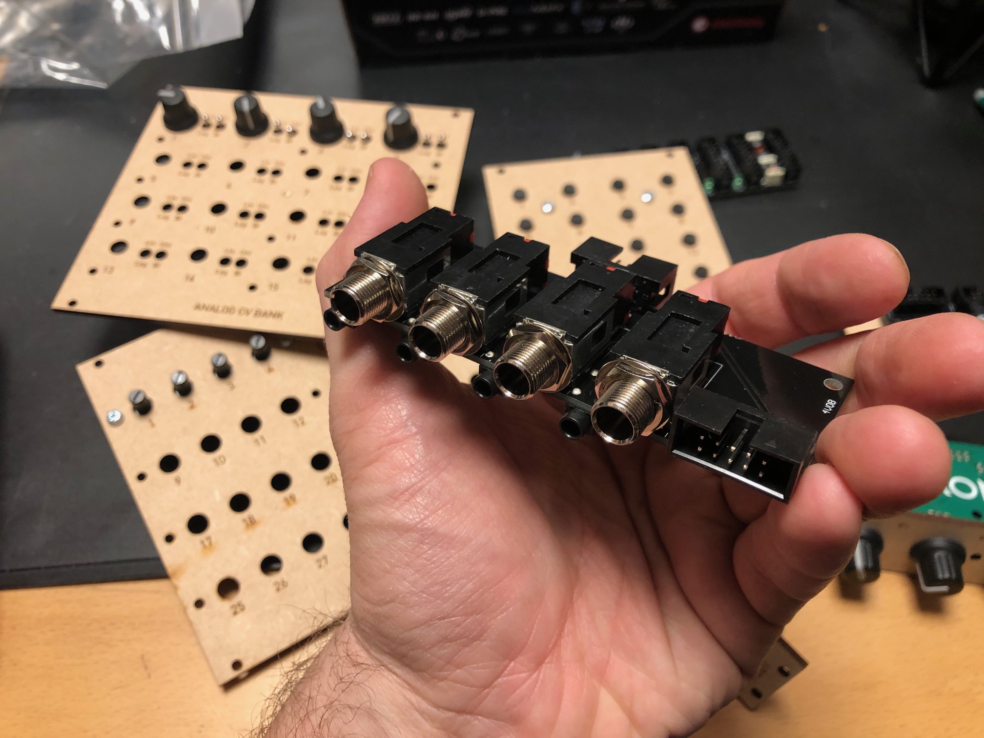
Quad input/output module with 1/4" jacks


For each module you can select input or output connected to the 1/4" jack, and the opposite will be connected to a minijack. Both ends are also connected to a 10p IDC connector for easy connection to a breadboard. For each channel there is an option of 10 or 2 x attenuation and 10 or 2 x gain, meaning you can either have a unity gain circuit, a 5x attenuation (for line out-ish) or 5x gain (for input).


24/48 button module, digital

A digitally scanned button module (without the microcontroller), chainable for up to 48 buttons. Serially read so it only requires four pins + power, making it possible to combine it with the potentiometer module on the same cable.


8 to 64 potentiometers module, digital


A digitally scanned potentiometer module (without the microcontroller). Each module has 8 potentiometers, and 8 modules may be chained for a total of 64 potentiometers. As with the button board, it only requires four pins, and it shares the same clock and reset pins at the button module so a total of six pins + power is needed for all digital modules. During testing I discovered that pin 9 on IC2 - one of the address lines - should have been connected to GND. Now it is floating, so it isn't possible to set the address correctly. It's an easy fix however.


4 x IDC Passthrough module

A simple panel with IDC connectors on both sides, makes it possible to route IDC connectors as a group through the front or back panel without putting the cable through a hole.


Bitcrusher

A combined 12 bit sample rate reducer and bit rate reducer with analog and digital control, based on a PIC16F18446 microcontroller with built-in ADC. Described in separate posts. I've ordered 25 of these.


20kHz LPF

A filter module that can be used as an anti-aliasing filter for ADC input and reconstruction filter for DAC outputs. I use the same configuration in the Bitcrusher and intend to use this for the combined DCO/wavetable oscillators. The circuit comes from this page: https://www.analogfilters.com/anti-aliasing-filter/


Voltage Controlled Distortion

A distortion module for the XM8, the second of the two pre-filter FX (the bitcrusher being the other). Controllable distortion amount and output amplitude, as well as switch between hard and soft distortion. Untested.


Memory


A DIL mounted SMD chip, 128Mbit, for use as sample memory for the wavetable oscillators etc. Untested.


Prophet VS keyboard controller

A new revision of the 68b01 clone for the Prophet VS. I've ordered 20 of these so I have for future sales. They have all been programmed but are missing legs.


Modular synth power bus board

16p Doepfer standard boards with 7 connectors. A bit short but cheap to build.


10p and 16p breadboard IDC connectors

Tiny boards with an IDC connector on one side and legs on the other, making it easy to use ribbon cables between breadboards and modules


Unbuilt designs

In addition, I have PCBs for the following that has NOT been soldered yet:


Breadboard power and I/O module

Has input for +/-15v and a regulator for 5V. Also has IDC connectors for chaining multiple boards, and small chain-boards that can be fitted upside down to connect multiple boards. Connects to the power busses on the breadboard. No more risk of messing up polarities! Also: a 10p Doepfer compatible power connector, although the doepfer uses +/-12V, not 15V, and a 10p I/O connector that connects a ribbon cable to 10 pin headers for easy and stable connections. Pin 10 may be connected to ground with a jumper.


Breadboard coax connector and I/O module

A board with four coax connectors and the same 10p I/O connector as the board above. Will give stable connection points for oscilloscop, function generator and other gear that uses coax.


15-to-12v DC converter module

A module that converts +/-15v from either a molex connector or a 10p IDC connector to +/-12v and +5v. Output is through a 16p connector, compatible with the Doepfer standard. Also has a two pin header for injection of Gate and CV 


All in all 16 different boards! Needless to say, I'm more than pleased! I'm getting so close to being able to test an initial voice board, I just need to program some digital envelopes.


Bonus

I finally got the following soldered and ready for testing:

Two versions of the sample and hold buffer, one with some large caps and some filtering and one in a tiny DIL14 format, both quad sample & hold:


Then the second version of the DCO, this time with DAC output to make it a wavetable oscillator too:


Saturday, August 8, 2020

Breadboards - distance between power busses

 I am making some utility boards for breadboard power supplies and i/o. 

This means I have to know the exact dimensions of the breadboards. 

The senter piece is easy - holes are about 0.1" apart (though measuring the exact dims it seems that they are often a little off, just not enough to be a problem). In addition there are two holes missing in the middle. Distance between the two outer holes is then 1.1" or 27.94mm.

By looking at the cards I expected the same to be true for the distance between the columns and the horizontal "busses", after all, this would seem the reasonable thing to do. But this turned out to be a mistake! 

I did some googling, and found a site that showed a board that had the distance between the outer busses as 1.85" (the expected would be 1.9 if all holes were 2.54" apart).

I then made my cards to this standard, but when doing a test print, this turned out to be too little... The busses on MY breadboards at least are further apart. To make things worse, there are differences between cards that look similar but are from different vendors/orders ("luckily" there is also differences in the spacing of the tabs that connects the cards so cards from different batches cannot be connected properly - making it easy for me to know what cards are from what batch).

So, I have to take some accurate measurements to figure out what is going on.


Here are the dimensions of my two batches of boards:

A: Power busses: 9.40mm, main part: 35.45mm, total w/gaps: 54.58mm

- gaps are 0.17mm

- padding around busses is 3.43mm per side

- padding on main part is 3.76mm per side

- calculated distance between outer bus lanes is 47.74mm = 1.879 inches


B: Power busses: 9.45mm, main part: 35.5mm, total w/gaps:54.64mm

- gaps are 0.12mm

- padding around busses is 3.46mm per side

- padding on main part is 3.78mm per side

- calculated distance between outer bus lanes is 47.74mm = 1.879 inches


Wow, that was a bit surprising. Even though things looked very different, the inaccuracies evened out to make the end result equal for both batches. With the pretty lose tolerances in the making of these cards, I'd say that 1.88 inches is probably the distance to aim for. Measuring using digital callipers give a very similar result for both cards. 


As for the bus distances between cards with two and tree busses between them, they should be:

2 busses (four lanes) - distance between outermost lanes of each card: 

A: 2 * 3.43mm + 0.17mm = 7.03mm

B: 2 * 3.46mm + 0.12mm = 7.04mm

0.275 inches is 6.99mm, which is a good approximation

3 busses (six lanes) - distance between outermost lanes of each card:

A: 2*3.43mm + 0.17mm + 9.40mm = 16.43mm

A: 2*3.46mm + 0.12mm + 9.45mm = 16.49mm

0.65 inches is 16.51mm, which is a good approximation


Tuesday, March 12, 2019

JP6 filter breadboarding

The last of the three filters I intend to do (at least initially) for the XM8 is on my breadbord. Well, partially anyway.

I have had so much trouble getting it to work, to the point where I ripped it apart and started over. Even then, I could not get it right. The times I could see a signal it quickly latched up etc.

Last night I finally got parts of it up and running after swapping out some opamps and going over the wirings again. I had among other things connected the I_abc of one of the cells to its own output, and connected a cap to the input instead of the output of another. Sigh. I am getting a bit stressed as my wife is having a baby sometime in May, so I'm pushing on to get the filter finished by then. Guess I'm a bit too tired!

Unfortunately, even if I could get a good signal for parts of the range, when the cutoff CV pot was above halfway I only got a lot of weird stuff.

I am currently using a 4x multiplier for the CV to get a full cutoff range. In my simulations, I got some strange oscillation on the signal at about 5.5V CV, which corresponds approximately to this point - which made me suspect that this was my problem.

And here I did what I had promised myself not to do until I had a working prototype: I looked at the System 80 Jove schematics. Sadly, they were almost identical to mine (no surprise there, as both are based on the Jupiter 6 service manual), but the Jove filter uses J112 JFETs instead of the opamp buffers.

I noticed that it also used 18k resistors on the OTA controls where I use 10k. I tried replacing the resistors in my simulation, and now the oscillation stopped - simply because the Iabc would never get high enough for the oscillation to start.

I did measure the cutoff for some currents in my simulation:

with 10k resistors:

5V: 593mA, 17kHz
5.5V: 1mA, 26kHz
6V: 1.37mA, 33kHz (oscillation)

with 18k resistors:

5V: 17kHz
5.5V: 21kHz
6V: 21kHz

Now, I tried replacing the resistors on the breadboard as well, but it didn't really change anything.

So, next up, I gave up on the TL082s. I only have two TL072s left and I suspect they are broken, so I hooked up a TL074 and ran wires to it. And suddenly the circuit worked! However, I did get the same oscillation, but sooner than expected.

I then replaced the 18k resistors with 10k again. This time the oscillation was gone!

But then, when I put my multimeter across the resistor to measure current, it returned - but only at very high cutoff.

More over, I realised that one of the 18k resistors had in fact been 1.5k. So my guess is that when the resistors are too different, one of the cells amplify more than the others and we get problems like this.

Anyway, I'm happy that I could get the filter working, and even better, that it worked at very high frequencies (>30kHz).