Showing posts with label jupiter 6. Show all posts

Monday, July 29, 2024

New PCBs from JLCPCB - Voice card ++

All new cards. Top left: Bus mixer, VCO and Juno filter. Top right: Moog and Jupiter filter. Center left: Voice mainboard. Center right: 2X waveshaper, FX module and bus mixer angled connector. Bottom: CV board
 
Everything mounted together. Looks a bit Frankenstein-ish but it fits!

Even the Juno filter, sandwiched between the voice card and the Moog/JP6 filter fits. I wonder how hot it will get though.

A true beauty!


Saturday, April 15, 2023

JP6 filter debugging, part 1

 Trying to breadboard a single cell of the JP6 filter. Here are my mods:

Errata:

R to -12V in cutoff CV input is 3.9R, should be 390k

op amp + and - are mixed up in cell input mixer

Modifications:

Skipping the part of reso generator that reverses CV, and leave out trimmers in reso circuit.


I inject resonance CV at reso gain 2 to bypass the inversion, and leave the reso bal unconnected. This makes reso CV go from 5 to 0 instead of 0 to 5. I use a 27k input resistor. (TODO: Why did I do that again? plot in simulation looks good at least. Probably what it was set to before removing the CV reversing and stuff in LTspice).

The cutoff CV mixer has an error (3.9R instead of 390k to gnd), so instead of using it i use the reso input mixer and a 330k to -12V on the input, still leaving balance floating. I then connect the output to a 20k trimmer, set at approx 6k (8k really, but in simulation it is 6k) and connect the output to cutoff track 2, bypassing the cutoff CV mixer.

Reso CV is set to 5V by using a resistor divider - 100k on top and 68k + 3k3 = 71k (should have been 71.4k).

Input to the cell: The input mixer is fucked up here too, I flipped it so + and - are mixed up. I use an external op amp instead, with a 33k feedback and a 100k input resistor. The output is fed to the in+ (pin 2) of the cell.

NB: SOMETHING IS MISSING HERE! pin 4 should be connected to pin 2. Anyway:

Now I can see that all three modes working - LP, BP and HP, though the input is weak and BP never really cuts off much. Next up is re-adding pin 4:

Aaaah, much better!

This time output at LP/BP/HP works. BP has a very soft cutoff slope but it DOES attenuate both above and below somewhat.

With 3.6k input with 5V max amplitude and cutoff CV at 0:

HP outputs 7.1V, BP around 750mV,  LP at -150mV


With 100Hz input, cutoff at 5V:

HP outputs -30mV, BP around 650mV and LP 7.6V

With 100Hz input and cutoff at 0V:

HP and LP are less, BP is at its max, which is 3.5V

Filter sweep, CV 0 to 5V, 1kHz input:


Reso is not tested but at least cutoff seems to work fine :)

HP and LP outputs max out at almost the same level (7.1 to 7.6V) while BP is half of that. In my simulations it looks more like HP and LP are 5V max while BP is around 3.5V.

The fact that BP has a lower amplitude is to be expected. Looking at a simulation, we can see that the bandpass peak (purple) is where the HP (red) and LP (green) meet, as it is really just a combination of the two filters.


If we want to avoid a loudness drop when using BP, we can amplify the output slightly. In this case I've added a non-inverting op amp with a gain of 1 + 33k/100k = 1.33. The result is the blue line above and below.

An added bonus is that we can use the same input resistor (56k and 100k here) to the second cell (we could do this without the gain as well, it only leaves the BP at the low level). We can also tap all filter types after the mux and move the resistors to the mux output.


Update: Tried using a 27k resonance CV input resistor and the 1.33 gain BP op amp, turned out very well. I think I can get away with a single 56k + 100k resistor now.

I also tried the notch circuit, which works as it should.

An interesting thought:

What if we just skip the varying resistors and just make up for it in the VCA/gain section? 


Next up: 

Figure out if we should have the mix resistors before the cell 1 output mux or after, what gives the least amount of noise

See why we tap direct output after mux but before 100k res, shouldn't tapping be before the output resistors? or do we need to buffer the signal between? (Note: The JP6 uses this layout, with one 56k from HP and one from LP, and adds this to the 100k input, effectively using 156k input to the summer of cell 2). 

Check output polarity from cell 1, including notch.


Tuesday, March 28, 2023

JP6 filter resonance CV

I'm testing the component based JP6 filter on a breadboard. I have some initial problems getting it to work, but then I realised that resonance is probably turned up way too high.

This made me take a look at how I generate the CV and how it affects the circuit.

This is the current circuit. The reason it is so large is that the resonance works backwards, feedback is needed to stop resonance rather than introduce it, so the CV is inverted from 0-5V to 0- -5V, then moved up 5V to get the correct response: 


Measuring CV vs I_abc/V_abc/V_collector. NB: For +/-15v supply
CV (V)I_abc (uA)V_abc (V)V_tran (V)
0-126.0-13.38-12.11
1-101.7-13.39-12.37
2-77.0 -13.40-12.6
3-52.0 -13.42-12.9
4-27.5 -13.46-13.18
5-2.7 -13.58-13.55


I have noted in my simulation that the CV must increase rapidly and then slow down, which means that I will have to manipulate the output from the synth matrix. In that case I may just as well just invert it while we're at it, so 5V is no reso and 0V is max. That really simplifies the circuit. Also, just using a 20k resistor at the input seems to work fine though it needs testing. In that case I reduce the number of trimmers needed by two, which is really good.


Measurements again - the results are similar to the previous ones, just reversed

CV (V)I_abc (uA)V_abc (V)V_tran (V)
00 -14.3 -14.28
1-24.8 -13.46-13.2
2-49.5 -13.42-12.9
3-74.3 -13.40-12.7
4-99.0 -13.40-12.4
5-123.8-13.38-12.14

It is interesting to note that the max current is so low (125-ish uA). It probably means that no change to the R_abc (which is 2 x 10k now) when switching to 12V supplies, though that has to be tested.

Tuesday, March 7, 2023

Filter FM and a dash of VCO linear FM research

It's time to hook up the FM inputs on the low pass filter.

I have an option to use both linear and exponential FM.

The most common option is exponential (v/oct) as this is readily available by mixing oscillator output with filter cutoff CV.

I found a nice post earlier about the use of both types but cannot find it right now, but here is a thread about linear FM at least:

https://modwiggler.com/forum/viewtopic.php?t=119415

FM off

I did initially design the FM input with two SPST (on/off) switches. This allows me to disconnect the input completely, as I was unsure how far down I could get the VCA to go.

Now I've done some calculations:

At 0V, the VCA has -80dB attenuation. That means that a 5V input signal would give a 0.5mV output.

If we've set the modulation to 1V/octave, 1 semitone would be 83.3mV, in which case 0.5mV = 0.6 cent. The input is bipolar (+/-5V) so the total change is 1.2cents.

For VCO tuning/tracking, I've assumed that a relative pitch change of about 3cent is at the limit of human hearing - and that's for VCOs. I think it is probably quite safe to use the VCA as a switch in this case. 

That leaves me with two options 

- either I use a DG413 as an SPDT switch, switching between lin and log - that saves me a single digital control signal. 

- or I use only exponential FM, in which case I don't need a switch at all.

I am currently breadboarding this. Both lin and exp FM works fine, but +/-5V linear FM seems to saturate something so the wave is cut off in some way. I will do a recording of it and add soon. Then I have to simulate the same to see what is actually going on. If I cannot make it work well I will just go for an exponential FM only.

Filter out: DCO1 is filtered, DCO2 modulates filter cutoff. Before red line: Linear FM, after: Exponential (v/oct) FM


Self resonance and exponential FM settings

Self resonancce and exponential FM output

Self resonance and linear FM output


Observations

Lin FM makes the filter "flatline". when the CV (DCO2) is low enough, the filter reaches a zero Hz cutoff, but the CV still goes lower, meaning the cutoff stays at 0Hz for some time - the filter does not support "through zero" modulation. 

PS: The output flatlines when input CV is positive, this is because the reference current is negative and any positive cv "negates" the reference current. Once the sum reaches 0 we cannot go any higher and the output flatlines.


Linear FM: When DCO2 is above a certain level,  the output "flatlines", presumably because cutoff reaches 0Hz before DCO2 reaches its peak.


Some measurements of linear FM CV vs I_abc

I_ref without any modulation is -12V / 1.2MOhm = -10uA (NB: mislabeled as -15V in captures)

With a +/-5V CV and a 120k input resistor, we will get 5V/120kOhm = 41.7uA, or approximately +/-4x the original I_ref. But since we cannot use an I_ref > 0, we get a flat line when the input from the linear FM CV reaches +10uA.


Cutoff CV: 0V, Lin FM CV: +/-5V


Cutoff CV: 2.5V, Lin FM CV: +/-5V


Cutoff CV: 3.5V, Lin FM CV: +/-5V


Cutoff CV: 4.5V, Lin FM CV: +/-5V


In my simulation I have written that we should use an input resistor that is approximately 10x the one used for the reference current, as that is what Yusynth.net uses for his VCO. That is not true.

Yusynth generates his reference current from a 5V source through a 1M resistor, giving a reference current of 5uA. For the linear FM input, he uses a 100k resistor, so a +/-5V input gives a +/-50uA output, which is 10x the normal reference current.

I, on the other hand, has used a CV that gives 4x reference current.


Cutoff CV: 0V, Lin FM CV: +/-5V, but this time we use a 50k lin CV input resistor


Calculations

To get a better feeling of the lin FM range I've done some simulations on the filter circuit. Here is the Frequency CV vs cutoff frequency vs I_control vs A/Hz (through a single cell):

1.0V:    10Hz    259nA    25.9nA/Hz

1.5V:    37Hz    1.03uA    27.8nA/Hz    

2.0V:    150Hz    4.18uA    27.8nA/Hz

2.5V:    604Hz    16.4uA    27.15nA/Hz

3.0V:    2.3kHz    63.6uA    27.7nA/Hz

3.5V:    8.2kHz    223uA    27.2nA/Hz

4.0V:    22.4kHz    639uA    28.5nA/Hz

4.5V:    42kHz    1.3mA    31.0nA/Hz

1.3mA is the highest possible value before we reach a flat top.


If we disregard the first and the last two (>= 4.0V) as we already know that they are not tracking that well, we get an average of 27.5nA/Hz


From my previous work I have that: 

R_linfm is often selected so that I_linfm = I_ref when linfm CV is at its highest (often 5 or 10V), which means that the frequency can be modulated by +/- 100% (the reference current will be between  0V and 2 * I_ref).

This is only true as long as we do not use through zero modulation. 

Also, looking at the Yusynth VCO with its 10x FM, this is clearly not what everyone does.


What are others doing. VCOs:

Rene Schmitz: 

https://www.schmitzbits.de/vco2.html

VCO 1-3: 15V / 1M ref current, 5V / 220k lin FM (15uA vs 23uA, ca 1.5x mod)

VCO 4 (TZFM) 15V / 470k ref current, 5V / 220k lin FM (32uA vs 23uA, or 0.72x mod)


Yusynth VCO

https://yusynth.net/Modular/EN/VCO/index.html

5V / 1M ref current, 5V / 100k lin FM (5uA vs 50uA, or 10x mod)


CEM3340

Pin 13 on the CEM3340 is the reference current summer. The datasheet has a 1.5M resistor to 15V and a 1M + 0.1uF cap to lin FM. In the last paragraph of the datasheet it says "The value of the input resistor should be selected so that the maximum peak to peak input signal produces a plus and minus current equal to the reference current". This is exactly what I have written in my own research on VCOs, so I guess this is where I got it from (?).

15 / 1.5M ref current, 5V / 1M lin FM (10uA vs 5uA, or 0.5x mod. Or, could it be they expected a +/-10V lin FM CV? In that case they follow their own doubling rule.


Ian Fritz

https://ijfritz.byethost4.com/sy_cir2.htm

6.9V / 690k ref current, 5V / 100k lin FM (10uA vs 50uA, or 5x mod)

https://ijfritz.byethost4.com/sy_cir16_teezer.htm

Hard to tell as lin FM is done differently


MFOS

https://hackaday.io/project/47158/gallery#ecedc0e5555ada3907345e3c0c4cda3d

A bit hard to tell, lin FM enters through the middle of a voltage divider??

12V / 1M ref current, 5V / (1M || 100k) lin FM (1M til summer) 


JJ Clark

https://electro-music.com/wiki/pmwiki.php?n=Schematics.XR2207VCOByProfessorJamesJClark

12V / 68k ref current (!), 5V / 10k lin FM (176uA vs 500uA, or 2.8x mod)


Thomas Henry

https://electro-music.com/wiki/pmwiki.php?n=Schematics.ACD4046BasedVCOByThomasHenry

15V/1.5M ref current, 5V / 100k lin FM (with AC/DC switch) (10uA vs 50uA, or 5x mod)


Lots of VCOs here: 

https://electro-music.com/wiki/pmwiki.php?n=Category.VCO


Ken Stone CGS48 VCO and VCF-ish thingie with built in VCO

https://electro-music.com/wiki/pmwiki.php?n=Schematics.Bi-N-TicFilterByKenStone

https://sdiy.info/wiki/CGS_VCO

15V/150k ref current, 5V/100k lin FM (100uA vs 50uA, or 0.5x mod)


Linear FM and "amplitude" in Hz

As described in more detail here, increasing the base frequency also increases the "amplitude" of the modulation (if you think about the FM as a bipolar signal). The higher you get the larger the change is. 

So, what to choose

That's the hard question, isn't it... Right now I'm having a hard time understanding why anything more than a 0-to-doubling of the reference current is used on a non-through-zero FM VCO/VCF. Once we go lower than 0 the average frequency starts to drop and the VCO goes flat. I guess that's an effect as well, but why do we want it? And why on earth would we want 10x the input as is the case on the Yusynth VCO? Hmm.... I guess the only way of finding out would be a proper test.

Update: After a little thinking I think (...) I will try this: Select an R_linfm that gives a I_linfm that is 4x the reference current. That way I can just divide the CV by four (= shift right 2) to get an I_linfm equal to I_ref, meaning that the output of the exponential divider will never be below 0. 

Juno filter FM

Incidently, for the juno filter with a 10uA I_ref, this whould mean a 125k resistor. My current design uses a 120k, which gives a 41.7uA max, or 10.4uA after division by 4. This is very close to the ideal. One could argue that a 130k would be better, making us not quite reach I_ref, but again, it's better to test. It is also possible that a 5V input to the VCAs does not give exactly a unity gain, so 120k, being a standard resistor value, may be good enough anyway.

VCO lin FM

As for the VCO, we have a slight issue. My current design expected a 15V input using a 1.5M resistor, giving a 10uA I_ref. Now, hopefully, I'll be able to tune away the difference, but selecting the proper R_linfm depends on whether I match it with the current design or with a possible updated/corrected design. Anyway, here are the two options:

For 10uA, I could use the same 120k or 130k resistor as for the juno VCF.

For 12V / 1.5M = 8uA i will need 32uA. The correct value would be 156k. The closest standard value is 150k which gives 33.3uA - again, a little high (3.5% vs 4% for the juno filter) but it may work anyway.

Jupiter 6 filter lin FM

This uses the same expo converter as the juno filter. Right now they both use 15V and 1.5M R_ref, giving an I_ref of 10uA. As I've already redone the Juno filter for 12V with a 1.2M R_ref I will probably do the same with the JP6 version. That means that I can use a 120-130k R_linfm here as well.

Moog filter lin FM

The current 15V version has a 1M R_ref, giving I_ref = 15V / 1MOhm = 15uA 

If we switch to an 800k version (or 820k perhaps) for the 12V version, we will keep the I_ref the same.

I_linfm would then be 60uA and we would need an 83.3k resistor.

If we continue using the 1M R_ref, I_ref would be 12uA. I_linfm would be 48uA and we would need a 104k resistor


Sunday, May 24, 2020

Both orders from JLCPCB has arrived!

Finally, after waiting for over two months, the second order from JLCPCB arrived yesterday. I now have loads of circuits to test:

- JP6-style SVF
- Juno-style OTA filter
- Moog-style ladder filter (but this requires some soldering)
- 4ch mixer
- 4 way VCA
- Three types of CV/sample and hold
- Noise
- VCO, CEM3340 w/waveshaper
- DCO
- Waveshaper
- Led ring

The quality is overall very good, though I have found at least one solder bridge and and one of the led rings appear to have been slightly reworked (oh, and I've already broken a led, but that was my own mistake).

Some pics:


4ch mixer and VCA, with room for v2164 or similar

Top: Waveshaper. Bottom: Ring modulator and 4ch CV buffer


VCO, DCO, two versions of S&H for CV buffering, DAC.


Monday, March 23, 2020

Three filter boards - Moog, Juno and JP

The three filters I've made - first the JP6-ish state variable filter, 10 modes in total.


Then the Juno filter, with selectable 12/24dB and overdrive (if I remember correctly)


And finally, the moog style ladder filter with 12/24dB and overdrive.


Cross modulation on JP8, JP6 and JX-8P

I was trying to find info about how the JP8 crossmod works last night, but ended up answering a post about it instead. Here is what I wrote:

TL;DR:
JP8 and JP6 crossmod is exponential FM of DCO 1 by DCO 2, JX-8P is amplitude modulation (ring modulation) of DCO 2 by DCO 1 (plus sync if wanted).
Details:
All of this should be fairly easy to figure out from the service manuals for the various synths.
Right now I'm looking at the JP8 service manual. Here, the output from VCO 2 - tapped after the waveform selector - is fed back to the exponential (v/oct) input of VCO 1. There is nothing going into the reference current input of VCO 1 (the circuit around op amp 1A on page 12 of the service manual), so the JP 8 has no linear FM.
The signal from VCO 2 goes through IC18A, which is a BA662 OTA, this acts as a voltage controlled amplifier/attenuator, and this is what is controlled by the panel potentiometer.
The same is the case for the JP-6, although here the signal is fed through a CEM3360 VCA. It is still sent back to the exponential input of VCO 2. Nothing is fed into pin 13 of the CEM3340 VCO so the JP-6 has no linear FM either.
The JX-8P is completely different. It doesn't have VCOs, it has DCOs, meaning the frequency is digitally controlled. It does NOT let the output of DCO 2 control the frequency of DCO 1, neither exponentially nor linearly. Instead, when crossmod is enabled (pos 1 or 2 on the PG-800 switch), the output of DCO 1 controls the amplitude (volume) of DCO 2, which I guess means that the output of DCO 2 is now DCO 1 times DCO 2, or exactly what is described as ring modulation in figure 2 here (given that it follows the gain requirements stated): https://www.keyboardmag.com/gear/on-synthesizers-amplitude-and-ring-modulation
PS: This means that, unlike what OP says about crossmod on the JX-8P, DCO 1 does NOT modulate the FREQUENCY of DCO 2, it modulates the AMPLITUDE.
In the circuit diagram the control for this part of the X-mod is labeled 'Metal', so it is very possible that this has the same effect as 'Metal' on the JX-3p, which is also described as a ring modulator type of sound. Interestingly enough, I cannot find any similar circuit on the JX-3p.
The JX-8P (and JX-3P) does also have a sync input on DCO 1 going to Q18, which is the transistor that resets the sawtooth of DCO 1 (i.e. sets the frequency). Sync comes from the same input that resets DCO 2, so whenever DCO 2 resets, so does DCO 1 (which means this is just normal hard sync I guess).

Tuesday, March 12, 2019

JP6 filter breadboarding

The last of the three filters I intend to do (at least initially) for the XM8 is on my breadbord. Well, partially anyway.

I have had so much trouble getting it to work, to the point where I ripped it apart and started over. Even then, I could not get it right. The times I could see a signal it quickly latched up etc.

Last night I finally got parts of it up and running after swapping out some opamps and going over the wirings again. I had among other things connected the I_abc of one of the cells to its own output, and connected a cap to the input instead of the output of another. Sigh. I am getting a bit stressed as my wife is having a baby sometime in May, so I'm pushing on to get the filter finished by then. Guess I'm a bit too tired!

Unfortunately, even if I could get a good signal for parts of the range, when the cutoff CV pot was above halfway I only got a lot of weird stuff.

I am currently using a 4x multiplier for the CV to get a full cutoff range. In my simulations, I got some strange oscillation on the signal at about 5.5V CV, which corresponds approximately to this point - which made me suspect that this was my problem.

And here I did what I had promised myself not to do until I had a working prototype: I looked at the System 80 Jove schematics. Sadly, they were almost identical to mine (no surprise there, as both are based on the Jupiter 6 service manual), but the Jove filter uses J112 JFETs instead of the opamp buffers.

I noticed that it also used 18k resistors on the OTA controls where I use 10k. I tried replacing the resistors in my simulation, and now the oscillation stopped - simply because the Iabc would never get high enough for the oscillation to start.

I did measure the cutoff for some currents in my simulation:

with 10k resistors:

5V: 593mA, 17kHz
5.5V: 1mA, 26kHz
6V: 1.37mA, 33kHz (oscillation)

with 18k resistors:

5V: 17kHz
5.5V: 21kHz
6V: 21kHz

Now, I tried replacing the resistors on the breadboard as well, but it didn't really change anything.

So, next up, I gave up on the TL082s. I only have two TL072s left and I suspect they are broken, so I hooked up a TL074 and ran wires to it. And suddenly the circuit worked! However, I did get the same oscillation, but sooner than expected.

I then replaced the 18k resistors with 10k again. This time the oscillation was gone!

But then, when I put my multimeter across the resistor to measure current, it returned - but only at very high cutoff.

More over, I realised that one of the 18k resistors had in fact been 1.5k. So my guess is that when the resistors are too different, one of the cells amplify more than the others and we get problems like this.

Anyway, I'm happy that I could get the filter working, and even better, that it worked at very high frequencies (>30kHz).

Monday, January 28, 2019

Jupiter 6 filter schematics cleanup

I've cleaned up the schematics a bit. This is the version with linear vca and resonance CVs, 10 modes, overdrive and possibly oscillation issues. It may change in the future.


Jupiter 6 All pass filter

This post

https://www.muffwiggler.com/forum/viewtopic.php?t=137105&start=all&postdays=0&postorder=asc&sid=3ef1fe17aeeff7d7fd87444b7188ac69

mentions that by mixing the input with 2 x the BP filter, you'll get an all pass filter. The same does this pdf:

https://www.analog.com/media/en/training-seminars/tutorials/MT-223.pdf


I tried this with some success. I had to disconnect the 33k resonance resistor, but after this I got a response with a slight 667 mdB notch.


I will try breadboarding this later.
The MT-223-pdf also mentions an alternative way of doing a notch filter:


Which gives this notch:


As opposed to the notch we get by mixing LP and HP:

Sunday, January 27, 2019

Jupiter 6 filter - overdrive and multiple output variations

Overdrive

With a 3.9k input gain feedback resistor I could easily pass a 20V p.p. wave through the filter without distortion. But I wanted to see if I could get a distortion similar to the moog filter, and yes, I could.

Swapping the 3.9k resistor with a 33k makes the filter overdrive close to 10V p.p, quite similar to the Moog.

This is of course pre-filter amplification. I have seen people talking about the minimoog doing feedback of the original signal through the external input jack, and this sounding better, so I'll try that next. I also need to come up with a good way to control overdrive, one that is not so dependent on input amplitude.
Input (green) vs output (blue). 33k input resistor, 50k output pot


Output variations

This being a state variable filter means it can produce a multitude of filter variations at the same time - low pass, band pass, high pass and notch. It is also two filters after one another, which means we can get various falloff. I've played around with this and come up with 10 variations that are more or less usefull:

12dB LP
24dB LP
12dB HP
24dB HP
6dB BP + 12dB LP
6dB BP + 12dB HP
Notch (first SVF)
Notch + LP
Notch + HP
Notch + BP

I am not sure of the usefullness of all these but the cost to add them all is very little. Here is how I indend to wire them, with resistor values giving the following 'plateau' gain.


Constant current inputs

Just like with the Juno and Moog filters, I've swapped the resonance and vca gain CV circuits for my own, linear designs. The VCA gain  control is exactly the same as for the Juno (but with slightly different part values), and has a similar deadband. The resonance on the other hand, is different. The resonance circuit works opposite of the one in the Juno, increasing the resonance OTA gain reduces the amount of resonance.

Because of this, increasing CV must decrease the output current. Also, when doing exponential conversion in software later, we must generate a negative exponentially decaying signal instead of an exponentially increasing one, which is too bad as it means that we cannot have a common control system for all filters. I will have to look closer into this.

CV vs I_abc for one resonance OTA, original Jupiter 6 circuit. With a linear response, a similar CV curve must be calulated in software.


Oh, and because of the way I did the linear control, we don't get a deadband.

Jupiter 6 filter - oscillation issue

I did a lot more work on the Jupiter 6 filter today.

First of all, I tried figuring out why I get oscillation on the input whenever cutoff CV was above 4.7V.

I have yet to figure out what is going on, but I tried replacing all ideal opamps with TL072 simulations and I still have the issue. I will have to breadboard the circuit to see if it is real or not.

But even so, there are a few things that make this happen:

1) When resonance CV is at 0V, I get oscillation if cutoff CV > 4.7 and input gain feedback resistor > 3.9k. With 4.7V CV I could use at least a 15k resistor without problems.

2) Decreasing the 33k resistor from input to the resonance OTA, or removing the line completely, fixes the problem

3) Increasing resonance also removes the issue.

All in all, it seems that anything that makes MORE current pass through the circuit causes this oscillation. I tried quickly reading up on op amp oscillation but no quick remedy was found. I also cut down on the circuit to the point where only the first SVF with constant current controls (no expo converters etc) and no output VCA was left and still had the issue.

Thursday, January 24, 2019

State variable filters, some quick resources

I found these resources while trying to understand how resonance defeat works in a state variable filter:

A very good general description
https://www.electronics-tutorials.ws/filter/state-variable-filter.html

Some more about gain and stuff
Says that passband gain should not be affected by Q (resonance)
http://sound.whsites.net/articles/state-variable.htm

All pass and equations
https://www.analog.com/media/en/training-seminars/tutorials/MT-223.pdf

Musical Applications of Microprocessors
Then I found this on a forum (which I unfortunately forgot to bookmark):

I first read about how SVFs work in Hal Chamberlin's book, Musical Applications of Microprocessors , where there's a lovely diagram of the filter's structure. I later spotted that same diagram in an article about an analogue computer. Apparently an SVF and a physical model of a spring have the same structure! Well, they're both dynamic systems that resonate, so I shouldn't be too suprised if they share the same mathematics.

Incidently I have this in my bookshelf, so I checked it, and it did indeed have a good diagram. But even better - it had an implementation using CA3080, which is almost exactly identical to the one in the Jupiter 6!


It's the first time I have come across that implementation, it even says that the capacitor-to-ground between the OTA and the buffer equals the configuration with the capacitor in the feedback loop of an opamp that I have seen elsewhere. Oh - and the book is from 1980, three years before the JP6 came on the market.


This one has both BP and band reject/notch. Oh, and it is missing the resistor i talked about in a previous post and has no change in gain for frequencies below the resonance frequency.


Matrix 12
I also looked at the Matrix 12 filter. It is NOT a state variable filter, it is a multimode filter, which mixes the output from four poles in various gain/variations to get 15 different responses. This matches well with what MT-223 above says about mixing different gains.

Cem chip used in the Matrix 12, CEM3372

https://pdf1.alldatasheet.com/datasheet-pdf/view/95160/ETC/CEM3372.html

On bandwidth vs Q:

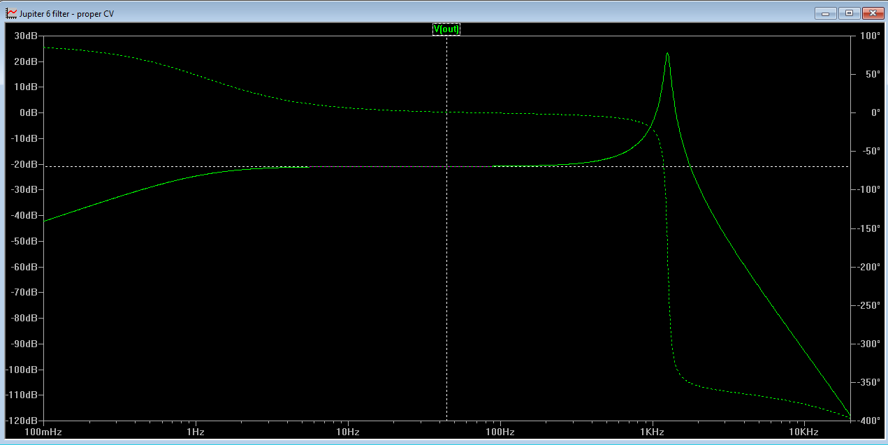
Jupiter 6 filter resonance gain

When I first simulated the jupiter filter, I had made a mistake. I forgot to connect a 33k resistor from the negative terminal of the resonance OTA and to the filter input. I didn't notice, and all my plots looked good. More than that - I actually could add resonance without the lower frequencies getting attenuated. Reading up on state variable filters today indicates that this is a feature of this filter topology (http://sound.whsites.net/articles/state-variable.htm)

When I corrected this error though, to my great surprise, lower frequencies got heavily attenuated once resonance went up!

I have checked and rechecked and traced the original JP6 PCB but I always come to the same conclusion - the resistor is there.

I even went back and simulated the filter with and without the resistor, looking at both filter response and phase, and honestly, I can't see ANY difference, except for the attenuation.

Zero resonance without resistor

Zero resonance with resistor


Max resonance without resistor, same low frequency gain as no resonance

Max resonance with resistor. gain has fallen by 24dB


This begs the question: What is the purpose of this resistor/line?

Right now my only two conclusions are either that it is there to attenuate lower frequencies on purpose - exactly the thing other filter designers fight to. Or LTspice simulates the circuit incorrectly.

I guess won't get an answer to the last question until I breadboard the circuit.

Update: Scott Bernardi made a comment about the attenutation here: http://www.bernacomp.com/elec/og2/og3_4pmultimode.html - Without it the resonance would start clipping (depending on the rest of the circuit of course). That makes sense.