Showing posts with label all pass. Show all posts

Thursday, August 10, 2023

Output levels, SVF Cell 1 & 2

Cell 1

I've measured the output levels of three different circuits for cell 1 of the SVF.

The results are fairly stable, within approx 0.05-0.1V between cells.

Output of LP, BP, HP and Notch are all around +/-5.5V when input is +/-5.0V. 

As I mix BP with input, and the output should be 2 x BP + Input, we have to reduce the input resistor for input to boost it from 5 to 5.5V approx. 

BP output is between +/-5.3 and +/-5.4 for all cards, so gain needs to be between 5.3/5 = 1.06 and 5.4/5 = 1.08 Experimentiation showed that using a 51k and 1.8k resistor in series, combined with the 56k feedback resistor, gave a good result. The calculated gain for this is 1.06.


Cell 2

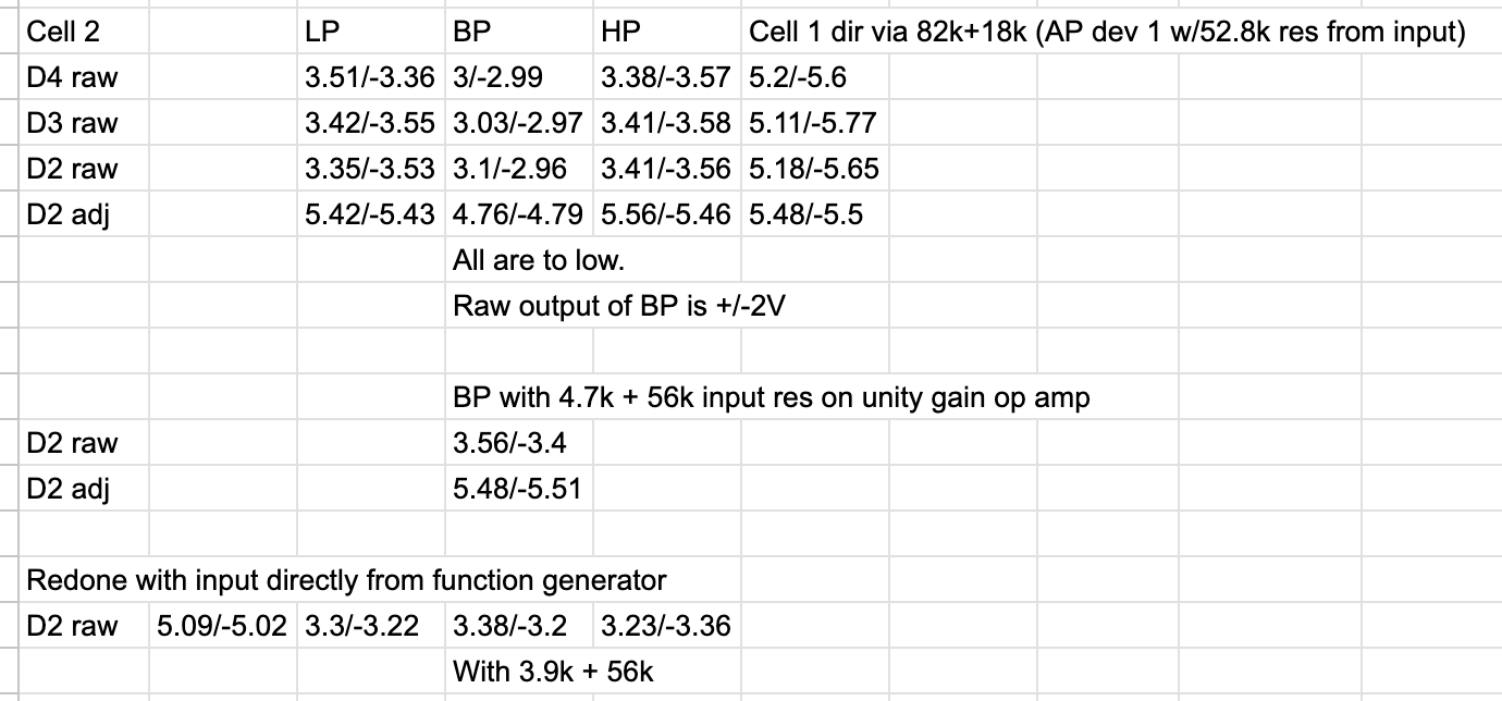
I did the same for Cell 2, testing device 2, 3 and 4 against each other, and again they match fairly well.

Raw output is around +/-3.4V with a little offset. BP, however, was too low even after the 100k/67k boost and came out around +/-3V. After some experimenting I chose to replace the 67k resistor with 4.7k + 56k, which brought BP up to the same as the others.

The output after final amplification is +/-5.4 to 5.5V which is approx the same as from cell 1. Not sure if I should adjust this back to +/-5V, as the input is 5V, I guess unity gain is a nice feature so perhaps worth the extra work.

Sunday, July 23, 2023

I don't understand how to use AP

Now that the AP is working properly on the JP6 filter, I'm trying to understand how to use it.

Most places say that you should mix it with the original signal, but when I do that I get exactly what I get from my notch:

Red: Notch. Blue: 50% AP + 50% Dry


Saturday, July 8, 2023

JP6 All-pass - inverting BP

In my simulations and breadboarding I added an inverting op amp for the input to get AP. But what if we instead inverted BP? It is already 180 degrees off compared to HP and LP. 

I simulated this, and it looks like it works well. Instead of going from -360 to 0 degrees it goes from -180 to 180, which is just to say that the output is inverted compared to the input - just like HP and LP.

As I'm already planning on having an invert button/switch on the SVF this doesn't matter :-D 

It also saves me one opamp.

As for the opamp gain, to keep the gain at 1.48 (or 1.5, it probably doesnt matter too much) we can go with 100k input and 150k feedback, or 68k/100k.

I will try this now.

JP6 All-pass tested

I've breadboarded and tested the AP-filter from my all-pass simulation, version AP-C: https://atosynth.blogspot.com/2023/04/jp6-filter-allpass.html

It only required minor tweaks.

During testing, my BP outputs +/-3.5V and the HP/LP outputs +/-5.2V. I assume that BP is affected the same way HP/LP is by the resonance feedback, so adjusting feedback so that HP/LP are normally +/-5V probably also affects BP amplitude.

Anyway, to get AP we need to mix 2x BP with the inverted input. But the BP needs to be unity gain.

If we assume that unity gain is +/-5V when properly adjusted, it is 5.2 when HP/LP is 5.2. That means that to bring it up from 3.5V to 5.2V we need a gain of 1.48. The simulated circuit has a gain of 1.33 when using a 100k/33k combination. Replacing the 100k with 68k gives us the gain of 1.48 that we want. 

Here is a video of turning the cutoff CV knob, see how the phase changes.


The resulting circuit is like this:


PS: We need to sum everything BEFORE it reaches the filter as we need input both for AP and normal input. But this affects the polarity of the input and probably also the feedback circuit.

PPS: I am not sure how we can use AP/Phasing. Do we need to be able to pan wet/dry to different channels? Should this be an option anyway for filter outputs?


Update: Here is an alternative circuit, the AP output phase is 180 degrees different from the one above but it saves one op amp that can be used to sum stuff before the filter


Sunday, April 23, 2023

JP6 filter allpass

 Since breadboarding the first cell of the JP6 filter was successfull, it's time to revisit the allpass circuit. I sort of got this working in an earlier post: http://atosynth.blogspot.com/2019/01/jupiter-6-all-pass-filter.html, but had to remove resonance feedback it seems.

I tried the same circuit in LTSpice again, mixing Bandpass output with the input tapped after the input mixer. It gives a nice phase change but the response is -10dB for the "normal" case, up to 4dB at the cutoff frequency, not very usefull. 


I then realised that mixing with the input may refer to the original input, not what is seen after the mixer. However, the input at this point is inverted, so we don't get the phase reversal effect we're looking for

NB: Not original BP but unity gain one


This is easily fixed by inverting with unity gain. Now we're talking. We get a flat response with a -6dB notch and the phase reversal we're after


I started thinking that this could be the best option, but the notch made me uncertain. After a bit of googling, I once again found the multimode filter pages at electricdruid. There, the following is stated: 

"Phase shifters produce a notch in the frequency response by mixing this phase-shifted signal with the input, so technically they’re a type of notch filter." 

Ok, so a notch is to be expected. I then found the link to "Craig Anderton's Multiple Identity Filter" article. I thought for a moment this confirmed my -6dB notch as it says -6dB notch at the end, but I mixed up notch and allpass. It is worth a closer look though.

But then I realised, what if I make sure BP output is the same as HP/LP etc, though my non-inverting amplifier, just as I did with the BP output from cell 1?

That works great!


The closeup doesn't look that great until you look at the axis. The input is just very slightly attenuated (-170mdB). Looking at all combinations together shows that it is essentially flat:

Red line is unity BP + inverted input


Now, this is great news. Of course this is just a simulation, and as I have seen earlier, the actual result on the breadboard is different, but I think I have the best starting point at least - mix the inverted input with the unity gain BP and we get a good all pass version!

Monday, January 28, 2019

Jupiter 6 All pass filter

This post

https://www.muffwiggler.com/forum/viewtopic.php?t=137105&start=all&postdays=0&postorder=asc&sid=3ef1fe17aeeff7d7fd87444b7188ac69

mentions that by mixing the input with 2 x the BP filter, you'll get an all pass filter. The same does this pdf:

https://www.analog.com/media/en/training-seminars/tutorials/MT-223.pdf


I tried this with some success. I had to disconnect the 33k resonance resistor, but after this I got a response with a slight 667 mdB notch.


I will try breadboarding this later.
The MT-223-pdf also mentions an alternative way of doing a notch filter:


Which gives this notch:


As opposed to the notch we get by mixing LP and HP: