Showing posts with label ltspice. Show all posts

Friday, April 19, 2024

Ring modulator LTSpice simulation

Before breadboarding the circuit again I thought it would be a good idea to simulate it to see what effects to expect when replacing pots and caps.

The circuit as found on the Yusynth pages (http://yusynth.net/Modular/EN/RINGMOD/index.html)

The LM1496-model was found here: 

https://forum.allaboutcircuits.com/threads/mc1496-monolithic-balanced-modulator-spice-model.47212/


With the pots centered, two 10Vpp input waves result in a 8Vpp output.

Signal and carrier

Green is output

With the 220Ohm pot fully turned to one of the sides, we get this:


With the 500Ohm pot fully turned to one of the sides, we get this:

It looks like the wave with the longest wavelength has gotten a DC offset

Now, if we replace the 220Ohm pot with a 500 one we get the exact same waveform when centered, byt at one of the sides we get this:

If we reduce the wiper to half way between center and one of the sides we get back to what we saw with 220Ohm:

It is thus likely that the 220Ohm potentiometer may be replaced with a 500Ohm one.

Cap biasing

The 1uF input cap on the left looks like it has one side DC biased between -3V and -4V:

The 1uF input cap on the right looks like it has one side DC biased around +7.5V

As for the 100uF cap, it is biased at around 6.5V. I cannot see any changes to the output whether I use a 200uF, 100uF, 10uF or no cap here, not with a combination of 1MHz and 10kHz, nor with the combination 1kHz and 10Hz. I think I will try using a 100uF ceramic even with the capacitance dropped to much lower by the DC bias issues such caps have.


Now, these are just simulations of course, so things may be different in practice, but it looks promising - I may be able to standardise on 500Ohm pots and use ceramics instead of electrolytics for the other caps. 

UPDATE: I have even used 500Ohm pots on my prototype so I will be fine :-D

EDIT: Input and output DC blocking / offset caps

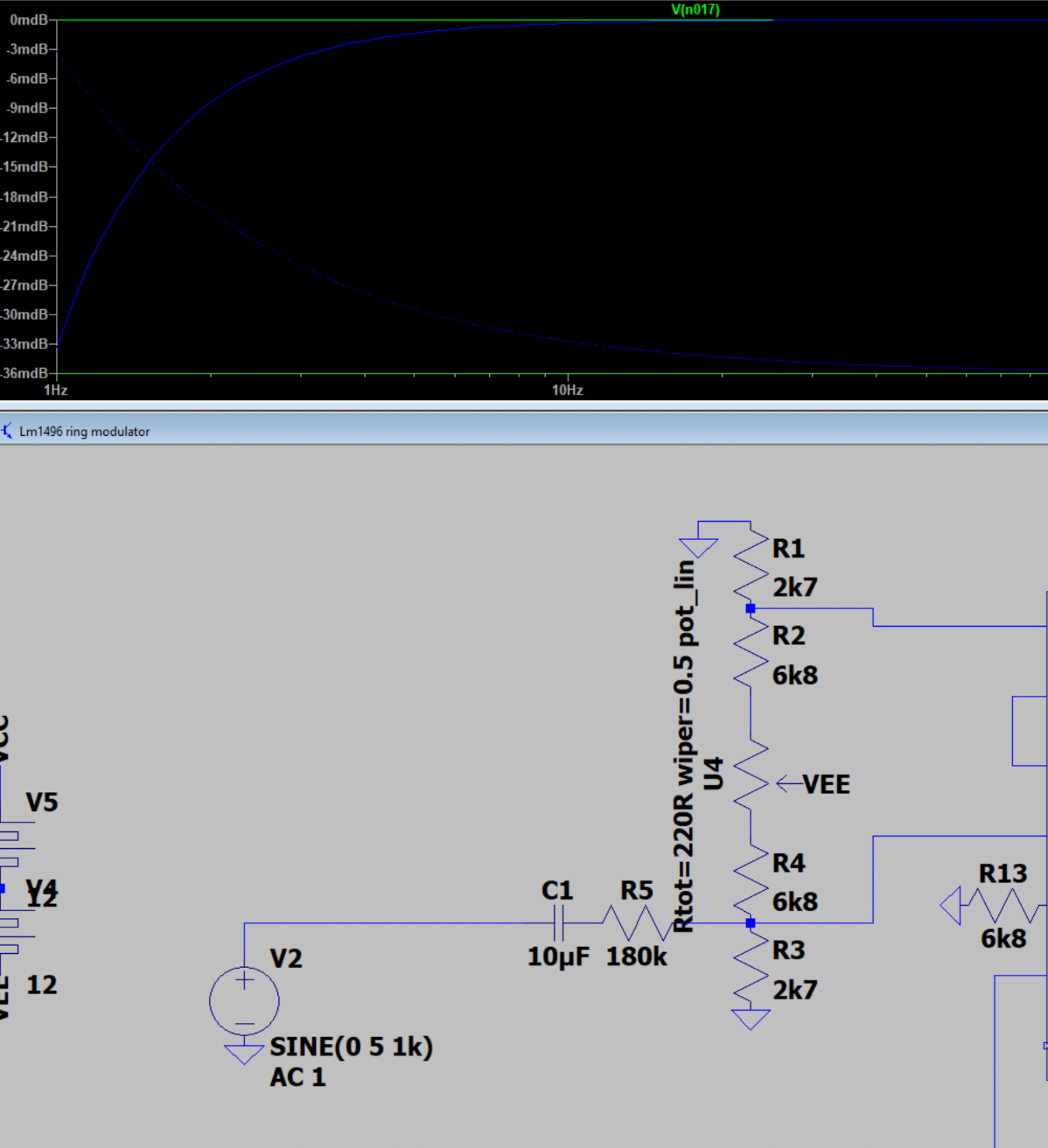
I simulated the frequency response for the input. A 1uF cap gives a 3dB point at around 1Hz.


As the cap is DC biased at 7.5V, its capacitance may in practice be as low as 0.1 to 0.2uF. It would then have a 3dB point around 10Hz.

If we use a 10uF cap instead, this would in the worst case have a capacitance around 1-2uF, matching the specified 1uF. If id is NOT reduced, a 10uF cap should have a 3dB point even lower than 1Hz and we should still be fine - I hope!


Sunday, April 23, 2023

JP6 filter allpass

 Since breadboarding the first cell of the JP6 filter was successfull, it's time to revisit the allpass circuit. I sort of got this working in an earlier post: http://atosynth.blogspot.com/2019/01/jupiter-6-all-pass-filter.html, but had to remove resonance feedback it seems.

I tried the same circuit in LTSpice again, mixing Bandpass output with the input tapped after the input mixer. It gives a nice phase change but the response is -10dB for the "normal" case, up to 4dB at the cutoff frequency, not very usefull. 


I then realised that mixing with the input may refer to the original input, not what is seen after the mixer. However, the input at this point is inverted, so we don't get the phase reversal effect we're looking for

NB: Not original BP but unity gain one


This is easily fixed by inverting with unity gain. Now we're talking. We get a flat response with a -6dB notch and the phase reversal we're after


I started thinking that this could be the best option, but the notch made me uncertain. After a bit of googling, I once again found the multimode filter pages at electricdruid. There, the following is stated: 

"Phase shifters produce a notch in the frequency response by mixing this phase-shifted signal with the input, so technically they’re a type of notch filter." 

Ok, so a notch is to be expected. I then found the link to "Craig Anderton's Multiple Identity Filter" article. I thought for a moment this confirmed my -6dB notch as it says -6dB notch at the end, but I mixed up notch and allpass. It is worth a closer look though.

But then I realised, what if I make sure BP output is the same as HP/LP etc, though my non-inverting amplifier, just as I did with the BP output from cell 1?

That works great!


The closeup doesn't look that great until you look at the axis. The input is just very slightly attenuated (-170mdB). Looking at all combinations together shows that it is essentially flat:

Red line is unity BP + inverted input


Now, this is great news. Of course this is just a simulation, and as I have seen earlier, the actual result on the breadboard is different, but I think I have the best starting point at least - mix the inverted input with the unity gain BP and we get a good all pass version!

Thursday, March 16, 2023

UPDATE: Flawed - LM13700 simulations, 12/15V supplies

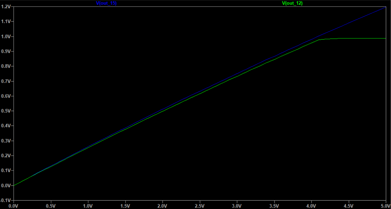
UPDATE: A lot of the values in this post are wrong, as the 5V CV in the 12V circuit made it flatline after about 4.5V CV. I will do a new post with a corrected circut but keep this to be able to see what I originally thought.

I_abc

V_out


Before converting the JP6 filter to 12V, I wanted to know a bit more about what happens when changing the supply of the LM13700 from 15V to 12V. (For simplicity, throughout this text I will say 15V and 12V when I actually mean a +/-15V and +/-12V supply voltage).

As a first model I used the Xonik VCA.

Xonik VCA

I first calibrated the circuit for unity output at 5VCV, 12V supply:


I then tried the same circuit with a 15V supply without changing anything else:

Slight offset of output when 15V supply, slightly reduced gain (surprisingly)

Finally I tweaked the resistors to get a centered output with 15V:
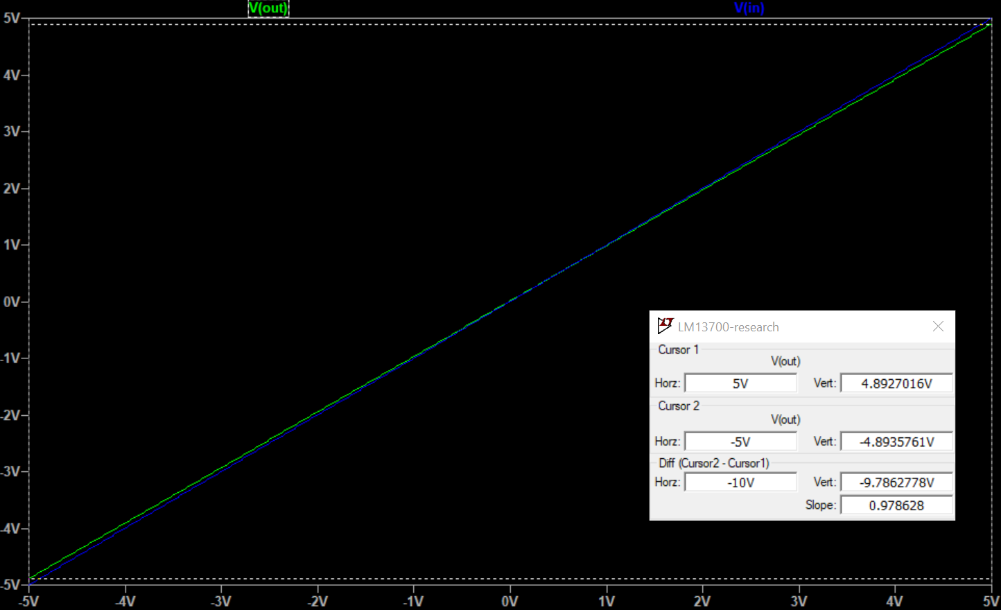
Centred output, 15V supply

Centred output, 15V supply - circuit

EDIT: After completing all measurements I went down the rabbit hole that is reading the datasheet. I discovered that (not that surprisingly really), the gain (transconductance) of the circuit is strongly dependent of the diode bias current. In my 12V version of the circuit this is set to 11.3V/12kOhm = 0.942mA (11.3V is one diode drop short of the positive supply voltage 12V, as anode of the diodes are 0.7V above 0), so when changing to 15V we need to replace the 12k resistor with a 15.19k one. This does not affect the control current generation but it DOES affect the gain, see the last line in the signal voltages table.

Measurements around the LM13700 on the Xonik VCA

CV inputs

CV Supply Icv (=-I emm) I base Iabc Vabc V coll V base
0V12V0V0V-11.29pA-11.289V-11.289V33nV
0V15V0V0V-14.27pA-14.266V-14.266mV33nV
5V12V-1.515mA-271uA-1.244mA-10.25V-49.9mV-788.7mV
5V15V-1.515mA-15uA-1.500mA-13.24V-942.33mV-784.7mV

These stay the same even if the diode bias current changes.


Signal voltages

  • input is -5 to 5V.
  • CV is 5V
  • +in is connected to input through a 27k resistor and has a 510R to gnd
  • bias input is connected to 12/15V through 12k resistor
  • Output is to gnd via 24.3k resistor, buffered.

Supply +in -in bias I out (to gnd) V out
12V 175mV to 275mV

(191.7uA to -175uA in 27k, 343uA to 539uA in 510R)
184.5mV to 265mV

(373uA to 536uA)
1.03 to 1.12V

(-914.5uA to -907uA)
-205 to 206.7uAV out: -5.02 to +4.98
15V 235.7mV to 234mV [THIS MUST BE WRONG, PROBABLY to 324mV)

(193.9uA to -172.8uA in 27k, 462uA to 654uA in 510R)
243mV to 325mV
(495uA to 662uA)
1.09 to 1.118V

(-1.1589mA to -1.1515mA)
-201.3 to 201.3uAV out: -4.89 to +4.89
15V* 175.6mV to 278mV

(191.7 to -175uA in 27k, 344.3 to 540.8uA in 510R)
184.9mV to 265.5mV
(376.8uA to 541uA)
1.03V to 1.12V

(-920uA to -914.2uA)
246.8uA to -245.4uAV out: -6.0V to 5.96V

*with changed diode bias using 15.19k resistor instead of 12k. 

Something interesting happened when I changed the diode bias resistor. All signal currents and voltages are suddenly the same as for 12V. The control currents/voltages are still different from 12V but they have not changed from the original 15V. The only thing that is different is I_abc. Let's see what happens when we change that to match the 12V input.

Changing the CV to 4.1465 changes I_abc to -1.244mA. Now the output is back at -5 to +5V! Hooray, this means that we have the exact same I_abc to gain tracking for 12 and 15V. In other words, I_abc tracking is the same as long as we use the correct diode bias.


With constant current source for Iabc


Signal voltage and currents (+/- in and bias) don't change.

Current response (Iabc vs output) changes when going between 12V and 15V. 

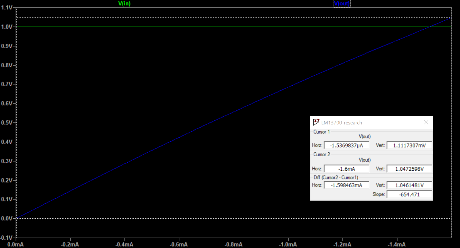
Examples with 1V input signal and 0 to -1.5mA (12V) and -1.6mA (15V):

12V source


15V source

TODO: Add new screenshot with corrected diode bias current.


With expo converter from Juno


12V

Original expo converter for 12V

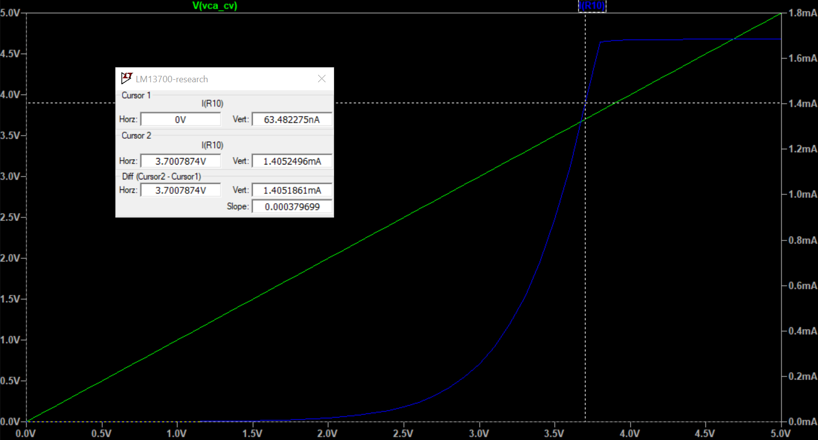
CV vs Iabc for 12V, with cursor set at max CV that gives a usable Iabc


CV vs Iabc for 15V but with same circuit and CV as 12V, Iabc is much lower than for 12V

Still same circuit as 12V but max CV for 15V. Max CV is higher than for 12V

TODO: New screenshots with corrected I_d

Now adapt circuit by replacing Rref with 1.5MOhm and offset with 412.5k to keep inputs the same

Adapted circuit to keep 15V same as 12V

Adapted circuit (15V) with same CV as max for 12V circuit. Iabc is now -1.41mA vs -1.31mA for 12V. Not that far off but still a few percent.

As above but with max CV for adapted 15V circuit


Voltages 12V

12V: Voltage at right transistor out

12V: Voltage at current input (V_abc)


12V: V_output with input = 1V

Voltages 15V

15V: Voltage at right transistor out

15V: Voltage at current input (V_abc)


15V: V_output with input = 1V


TODO: Explain why voltages after transistor changes (current source?)

TODO: Regne på om I_abc vs gain endrer seg mellom 12 og 15V

Monday, January 28, 2019

Jupiter 6 filter schematics cleanup

I've cleaned up the schematics a bit. This is the version with linear vca and resonance CVs, 10 modes, overdrive and possibly oscillation issues. It may change in the future.


Monday, December 31, 2018

A closer look at responses for the Jupiter 6 filter

NB: This post was written before i discovered a missing 33k feedback resistor. Results are not correct

To make a good state variable filter with 12/24dB HP, LP and 12dB BP I simulated the JP6 filter and tapped it at various places to look at the responses.

For my simulated circuit, setting cutoff CV to 0.2V (this has nothing to do with 1V/oct CV btw, look at the circuit to see exactly how it is wired) and Resonance CV to 10V (=off, see this post for details), gives the following results:

24dB LP:
- Cutoff: 507Hz
- Resonance (3V CV): 14dB at 953Hz

24dB HP:
- Cutoff 2kHz
- Resonance (3V CV): 13.7dB at 1.05kHz

12dB HP + 12 dB LP
- LP cutoff: 1.77kHz
- HP cutoff: 574Hz
- Center: 1kHz
- 10dB attenuation on top
- Resonance (3V CV): Top has 13dB amplification

12dB LP + 12dB HP
- LP cutoff: 1.77kHz
- HP cutoff: 574Hz
- Center: 1kHz
- 10dB attenuation on top
- Resonance (3V CV): Top has 13.5dB amplification

12dB LP with connection to second stage
- Cutoff: 666Hz
- Base attenuation 1.35dB
- Resonance (3V CV): Top has 6dB amplification over base at 885Hz, base is -1.26dB

12dB LP without connection to second stage
- Cutoff: 666Hz
- Base amplification 1.6dB
- Resonance (3V CV): Top has 7dB amplification over base at 885Hz, base is 1.6dB

12dB LP with connection to second stage
- Cutoff: 1.38kHz
- Base attenuation 1.2dB
- Resonance (3V CV): Top has 6dB amplification over base at 1kHz, base is -1.18dB

12dB HP without connection to second stage
- Cutoff: 1.4kHz
- Base amplification 1.7dB
- Resonance (3V CV): Top has 7dB amplification over base at 1kHz, base is 1.7dB


Sunday, December 30, 2018

Juno filter for the XM8

UPDATE: This filter circuit has some limitations to its maximum cutoff frequency and high frequency tracking. I will post an updated version that adresses these problems.

I have simulated a Juno filter, based on various designs found on the net. I have made a few deviations from the original Juno filter:

- Frequency tuning happens before the frequency 1V/oct mixing point. The Juno has if after, which means that chaning the tuning also changes the tracking. My change may have messed up other things, no guarantees there. My version makes it easy to set the base frequency over several octaves. NB: The resistor and pot values in my schematics may not be ideal.

- Input audio is attenuated heavily. In my simulations, anything above 1V p.p gets distorted. I have chosen to allow +/- 10V audio. R29/R30 do the attenuation, and changed values for R27 and R26 make up for it in the output stage.

- Resonance control is 0-5V but highest possible resonance equals what we would get from 10V in the juno. This corresponds to a maximum control current of 0.25mA, approximately what I found in the specs in my post about the ba662. I still need to see how this works out i practice. The control curve is different too.

- Output is now in phase with the input

- Filter has unity gain at 5V CV (or slightly above it).

- Freq CV in the schematics is 0.5V/oct to get a 10 octave range from 5V CV, the summing point has 1V/oct when using 100k input resistors.

I have suggested two alternatives for R26, R27 and R38 - choose the one with the range you need for the input voltage. the 10Vp.p alternative will probably distort for higher amplitudes while the 20Vp.p is probably more noisy as it attenuates and amplifies more to run the core at the same amplitude.

R26 may be replaced with a 100k resistor and a 200k potentiometer (for the 20Vp.p version) to be able to tune the output VCA max amplitude.

U15 adjusts tracking, U14 sets initial frequency, U16 adjusts output symmetry.

PS: The filter may be tapped after the second pole (the output of U4) for 12dB instead of 24dB response.

Simulated circuit


0 - 10V resonance (original circuit from Juno 106). 1V/step
0 - 5V resonance, modified circuit. 1V/step


Still to do: check response curve for the VCA CV.