UPDATE: A lot of the values in this post are wrong, as the 5V CV in the 12V circuit made it flatline after about 4.5V CV. I will do a new post with a corrected circut but keep this to be able to see what I originally thought.
I_abc V_out
Before converting the JP6 filter to 12V, I wanted to know a bit more about what happens when changing the supply of the LM13700 from 15V to 12V. (For simplicity, throughout this text I will say 15V and 12V when I actually mean a +/-15V and +/-12V supply voltage).
As a first model I used the Xonik VCA.
Xonik VCA
I first calibrated the circuit for unity output at 5VCV, 12V supply:


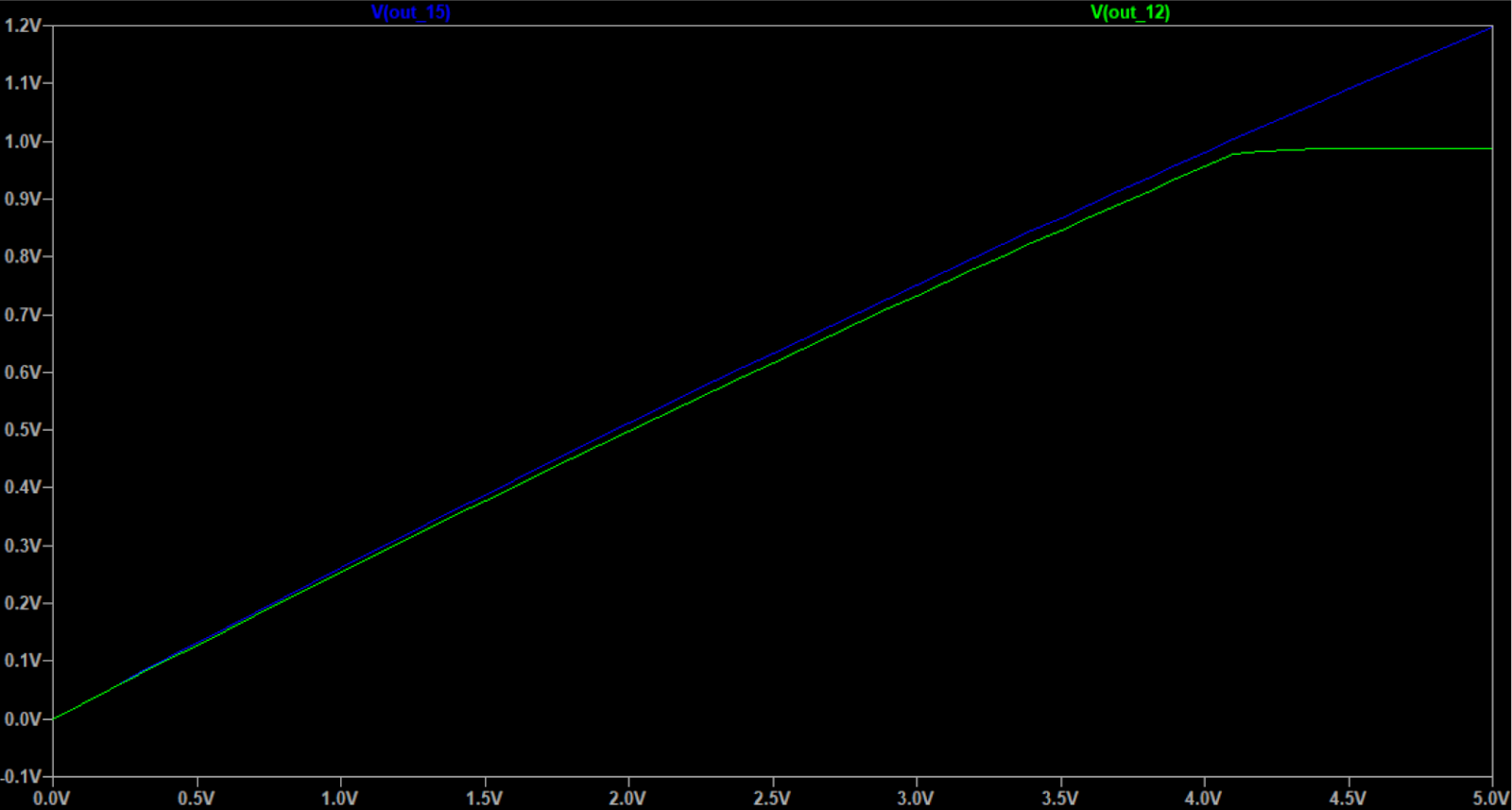
I then tried the same circuit with a 15V supply without changing anything else:
 |
| Slight offset of output when 15V supply, slightly reduced gain (surprisingly) |
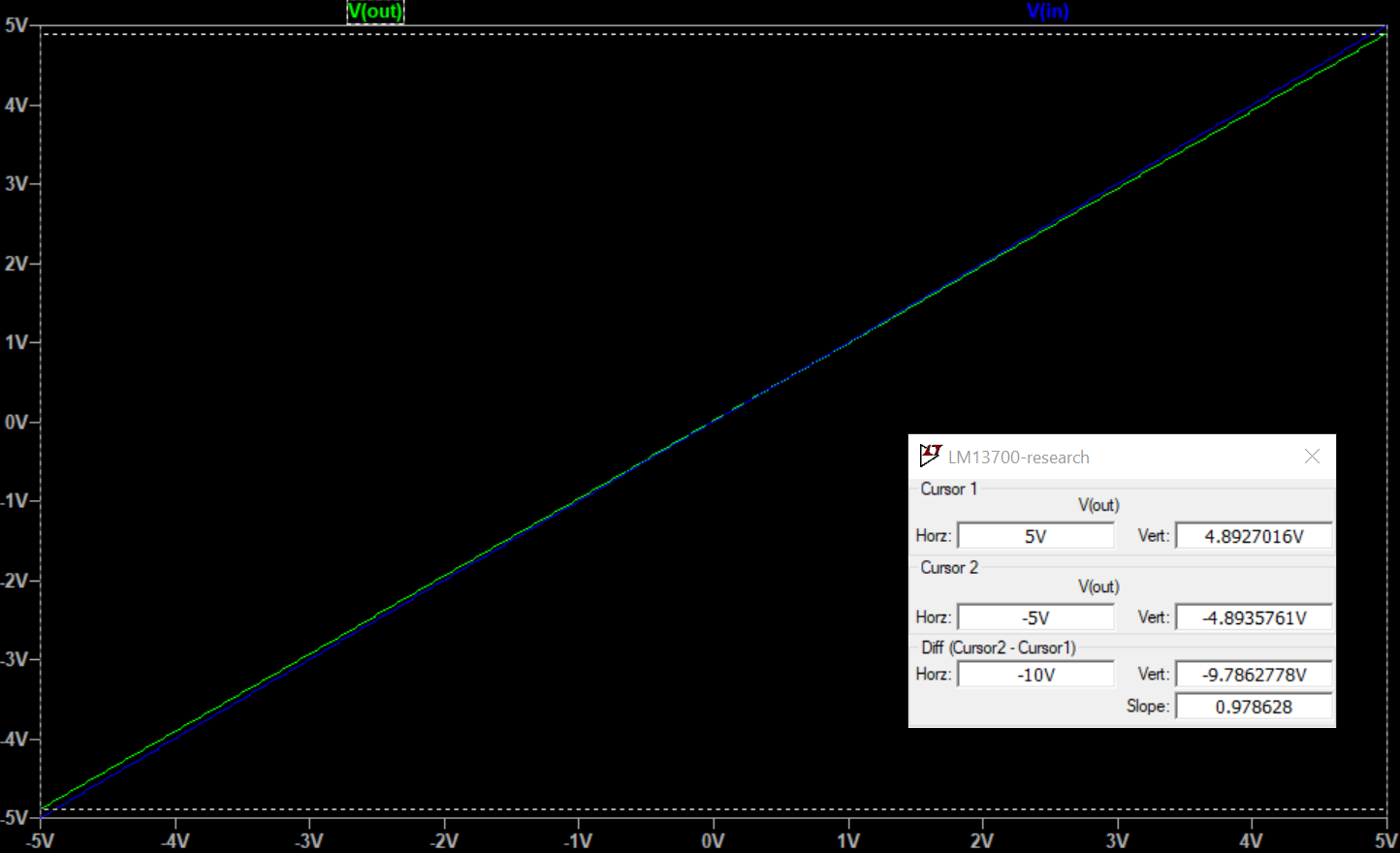 |
| Centred output, 15V supply |
 |
| Centred output, 15V supply - circuit |
Measurements around the LM13700 on the Xonik VCA
CV inputs
| CV | Supply | Icv (=-I emm) | I base | Iabc | Vabc | V coll | V base |
| 0V | 12V | 0V | 0V | -11.29pA | -11.289V | -11.289V | 33nV |
| 0V | 15V | 0V | 0V | -14.27pA | -14.266V | -14.266mV | 33nV |
| 5V | 12V | -1.515mA | -271uA | -1.244mA | -10.25V | -49.9mV | -788.7mV |
| 5V | 15V | -1.515mA | -15uA | -1.500mA | -13.24V | -942.33mV | -784.7mV |
These stay the same even if the diode bias current changes.
Signal voltages
- input is -5 to 5V.
- CV is 5V
- +in is connected to input through a 27k resistor and has a 510R to gnd
- bias input is connected to 12/15V through 12k resistor
- Output is to gnd via 24.3k resistor, buffered.
| Supply | +in | -in | bias | I out (to gnd) | V out |
| 12V | 175mV to 275mV (191.7uA to -175uA in 27k, 343uA to 539uA in 510R) |
184.5mV to 265mV (373uA to 536uA) |
1.03 to 1.12V (-914.5uA to -907uA) |
-205 to 206.7uA | V out: -5.02 to +4.98 |
| 15V | 235.7mV to 234mV [THIS MUST BE WRONG, PROBABLY to 324mV) (193.9uA to -172.8uA in 27k, 462uA to 654uA in 510R) |
243mV to 325mV (495uA to 662uA) |
1.09 to 1.118V (-1.1589mA to -1.1515mA) |
-201.3 to 201.3uA | V out: -4.89 to +4.89 |
| 15V* | 175.6mV to 278mV (191.7 to -175uA in 27k, 344.3 to 540.8uA in 510R) |
184.9mV to 265.5mV (376.8uA to 541uA) |
1.03V to 1.12V (-920uA to -914.2uA) |
246.8uA to -245.4uA | V out: -6.0V to 5.96V |
*with changed diode bias using 15.19k resistor instead of 12k.
Something interesting happened when I changed the diode bias resistor. All signal currents and voltages are suddenly the same as for 12V. The control currents/voltages are still different from 12V but they have not changed from the original 15V. The only thing that is different is I_abc. Let's see what happens when we change that to match the 12V input.
Changing the CV to 4.1465 changes I_abc to -1.244mA. Now the output is back at -5 to +5V! Hooray, this means that we have the exact same I_abc to gain tracking for 12 and 15V. In other words, I_abc tracking is the same as long as we use the correct diode bias.
With constant current source for Iabc
 |
| 12V source |
 |
| 15V source |
TODO: Add new screenshot with corrected diode bias current.
With expo converter from Juno
 |
| Original expo converter for 12V |
 |
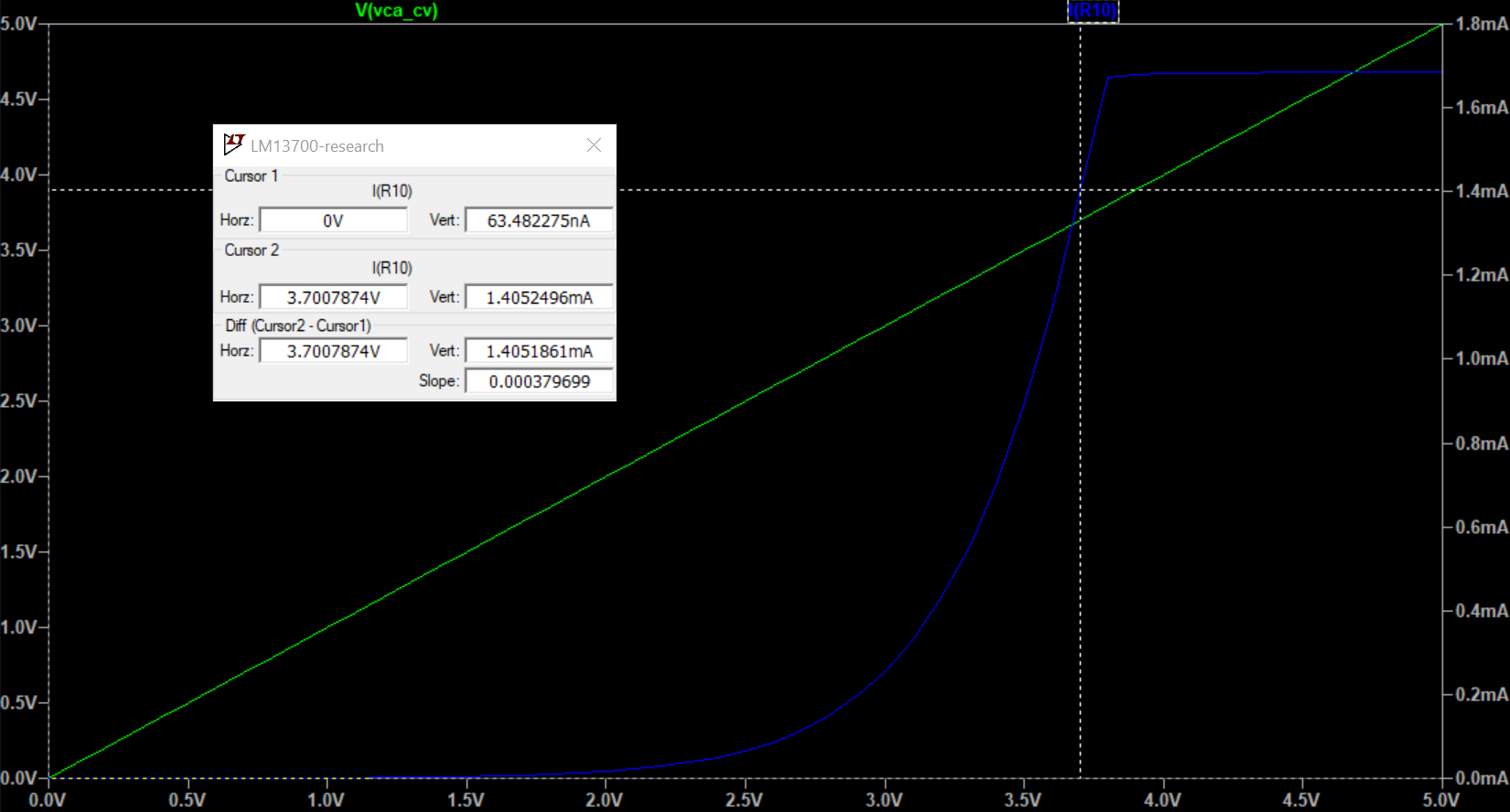
| CV vs Iabc for 12V, with cursor set at max CV that gives a usable Iabc |
 |
| CV vs Iabc for 15V but with same circuit and CV as 12V, Iabc is much lower than for 12V |
 |
| Still same circuit as 12V but max CV for 15V. Max CV is higher than for 12V |
 |
| Adapted circuit to keep 15V same as 12V |
 |
| Adapted circuit (15V) with same CV as max for 12V circuit. Iabc is now -1.41mA vs -1.31mA for 12V. Not that far off but still a few percent. |
 |
| As above but with max CV for adapted 15V circuit |
 |
| 12V: Voltage at right transistor out |
 |
| 12V: Voltage at current input (V_abc) |
 |
| 12V: V_output with input = 1V |
Voltages 15V
 |
| 15V: Voltage at right transistor out |
 |
| 15V: Voltage at current input (V_abc) |
 |
| 15V: V_output with input = 1V |
No comments:
Post a Comment