Showing posts with label cell 1. Show all posts

Friday, August 18, 2023

Output phase, SVF Cell 1 and 2

Cell 1


LP, BP and HP are in phase with the filter input (which is NOT the cell input, but IS the summing point for feedback).

Notch, however, is reverse before and after the notch point. This means it will not work with feedback. I address this further down in this post.

Allpass is in phase before and after the cutoff frequency, and 180 degrees off at the cutoff frequency. I am not sure if this is wrong and has to be corrected, I need to check the expected behaviour, though I believe that adding AP and dry should give a notch, which is what would happen here as the 180 degrees off at cutoff would cancel out the dry signal.

Cell 2
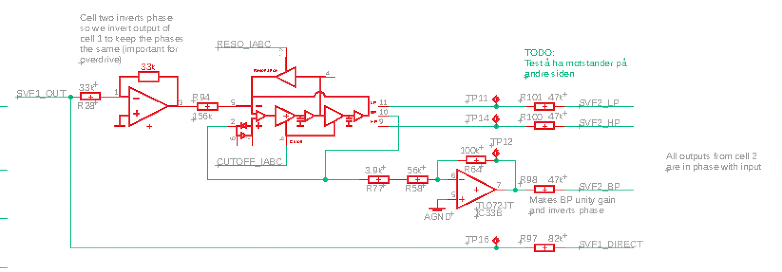
Cell 2, all outputs are in phase with input


The outputs of Cell 2 (as seen by the mux) is in phase with its input (Holds true for LP, BP and HP, and of course for the Cell 1 direct as this is the same as the input to Cell 2).

The op amp after the mux inverts the signal so the output phase of the filter is inverted. 


This affects both the output itself and the filter feedback. The output phase is selectable so that's taken care of there. The feedback on the other hand, is inverted back in the feedback VCA (positive input + inverting op amp).

Feedback VCA inverts signal

Alternative notch

Combining dry (inverted) and BP (unity gain) can give me notch without having to add another op amp (as described here: http://atosynth.blogspot.com/2019/01/jupiter-6-all-pass-filter.html)


Simulating this shows a big difference in the offness of the notch - green is LP + HP, red is dry + BP.


From the simulation, LP + HP results in a -1.2dB down to -36dB notch. Dry + BP results in -19.5dB.


Measured in my circuit I see approx +/-150mV for LP+HP, though it looks a bit noisy. Dry + BP is +/-375mV.


Also, gain when no notch is a little low:


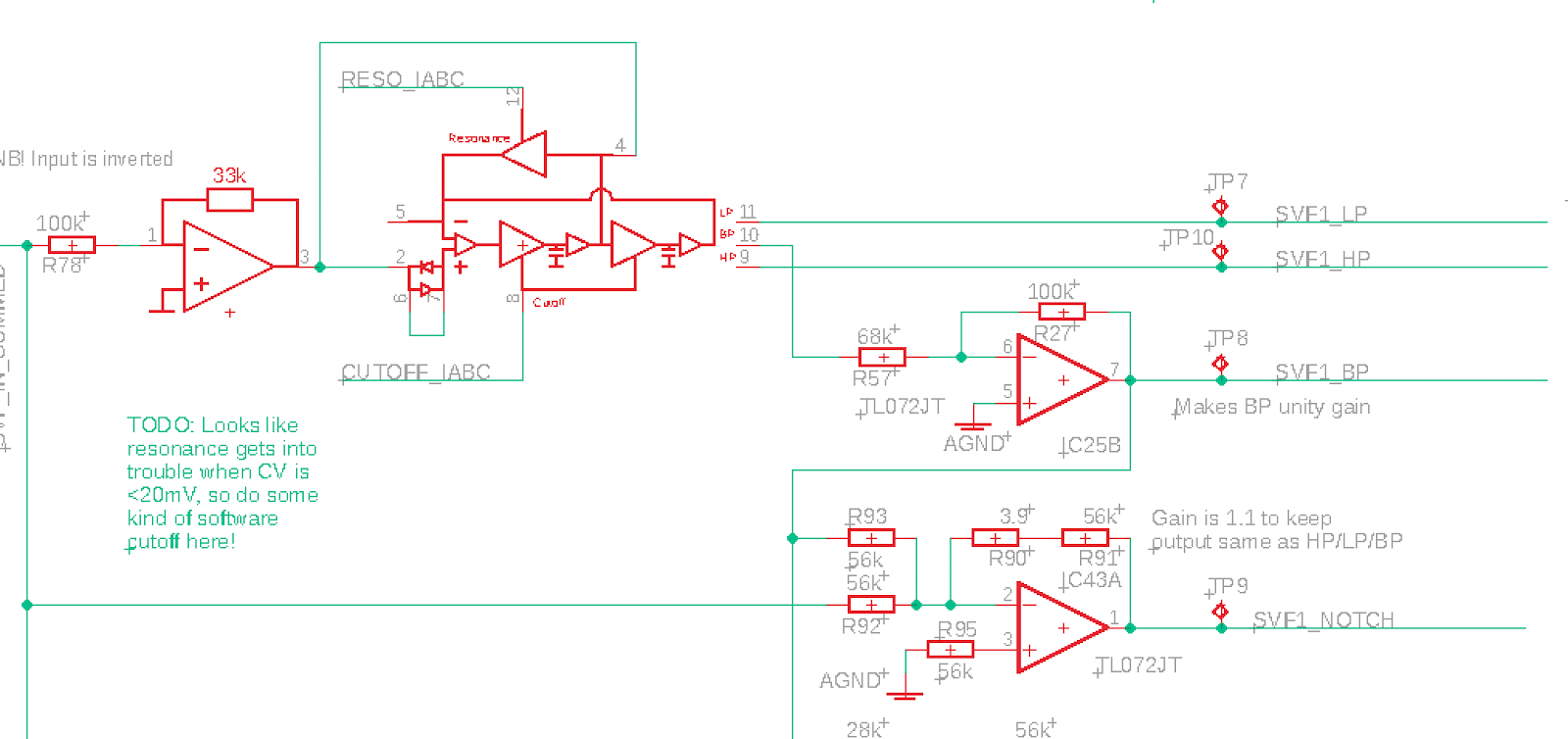
The output is +/-5V. To boost it to +/-5.5V which is the range of the other waveforms, we can use 56k + 3.9k in op amp feedback, making the gain 1.07

Here is the alternative notch circuit:


Thursday, August 10, 2023

Output levels, SVF Cell 1 & 2

Cell 1

I've measured the output levels of three different circuits for cell 1 of the SVF.

The results are fairly stable, within approx 0.05-0.1V between cells.

Output of LP, BP, HP and Notch are all around +/-5.5V when input is +/-5.0V. 

As I mix BP with input, and the output should be 2 x BP + Input, we have to reduce the input resistor for input to boost it from 5 to 5.5V approx. 

BP output is between +/-5.3 and +/-5.4 for all cards, so gain needs to be between 5.3/5 = 1.06 and 5.4/5 = 1.08 Experimentiation showed that using a 51k and 1.8k resistor in series, combined with the 56k feedback resistor, gave a good result. The calculated gain for this is 1.06.


Cell 2

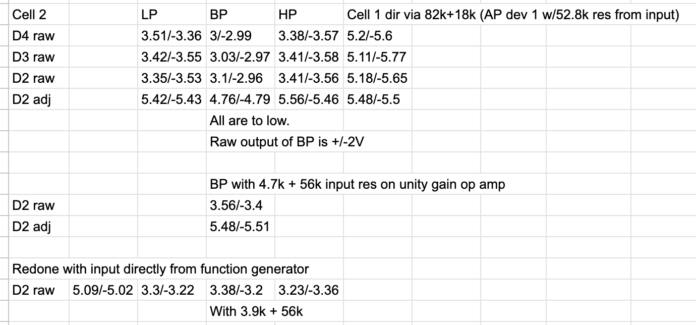
I did the same for Cell 2, testing device 2, 3 and 4 against each other, and again they match fairly well.

Raw output is around +/-3.4V with a little offset. BP, however, was too low even after the 100k/67k boost and came out around +/-3V. After some experimenting I chose to replace the 67k resistor with 4.7k + 56k, which brought BP up to the same as the others.

The output after final amplification is +/-5.4 to 5.5V which is approx the same as from cell 1. Not sure if I should adjust this back to +/-5V, as the input is 5V, I guess unity gain is a nice feature so perhaps worth the extra work.