Showing posts with label overdrive. Show all posts

Friday, August 29, 2025

Adding overdrive to the ladder filter

If I need to add overdrive to the ladder filter, I can free up one CV channel already routed to the board by using the same CV for trimming 2 and 4 pole output. I just need to store the trimmer value for each and switch between then when switching mode.

Another thought is - the little phatty does not use trimmers on any of the OTAs, perhaps one can get away without them? 

Thursday, August 28, 2025

Little Phatty overdrive

I can't remember if I've written about this before, but I've certainly looked at it.

EDIT: Turns out I did, in great detail! https://atosynth.blogspot.com/2024/01/moog-overload-circuit.html

I'm trying to retrofit overdrive to my ladder filter, so I had a closer look at how the little (and slim) phatty does it. The slim phatty schematics are available online but the circuit is spread across multiple pages so it's a bit harder to see what is going on.

Here is a simplified schematic:


There are a few surprises here:

- there is no feedback from the filter output to input, which is the way the minimoog achieves overdrive.

- it uses a pretty standard soft clipping circuit with CV-controllable clipping - the overdrive of the minimoog filter, if I recall correctly, happens in the transistors of the differential amplifier at the end of the filter.

- the output of the overdrive is fed back to the oscilllator mixer and returned to the soft clipping circuit

- the mixer is not a normal inverting summer op amp - it's just an op amp buffer, with all inputs connected to the positive input. This is possible because the OTA outputs are current, not voltage outputs

- the differential amp of the filter is realised using op amps, which won't give soft clipping when overdriven. 

- the filter has an additional output gain OTA.

It's a pretty neat circuit, and all three OTAs - feedback, distortion and post-filter gain - are driven from the same CV. 

 All CVs are biased in various ways, to +5 or -5, I haven't studied exactly how they work in conjunction. Neither is it clear to me if the post filter OTA contributes to the overdrive in any way or if it just makes up for lost gain during overdrive.


Major take-away

Distregarding the post filter gain, all distortion happens before the filter, just as I'm currently doing in my synth. I don't have the additional feedback OTA though, whatever that does. 


Sunday, January 28, 2024

Moog overload circuit

Since my previous posts I've gotten some feedback from the Modwiggler forums about the breakdown I see when overdrive/feedback is high. The answer is that this is normal for positive feedback, which I guess is ok. I've since chosen to abandon the per-filter overdrive in place of my own pre-filter distortion.

I've taken a closer look at the Little Phatty (LP)/Slim phatty overload circuit to see how the professionals do it, and to see if the circuit exhibits the same behaviour.

The LP overload is a combination of two things - first, a voltage controlled distortion that puts an OTA in the negative feedback of an op amp, basically acting as a voltage controlled resistor. This is the same solution I'm using for my distortion. But then it also has a second OTA that feeds the output back to the oscillator/source mixer. This is positive feedback, much like what I'm doing on the filters.


Overload circuit uses two OTAs

In addition to the two OTAs in the overload circuit, the overload CV controls a VCA after the filter, more about this towards the end.

LP CV generation

The CVs on the LP is generated by a DAC8581. This is a bipolar DAC that outputs +/- a ref voltage. The reference voltage is 4.096V. The voltage is then fed through an op amp gain circuit, which has a trimmer in the negative feedback. I've simulated this, and at the extremes the trimmer has an output of around 4.7 to 5.5V. Thus, I assume the trimmed output is supposed to be +/-5V, at least this makes it easier to reason about the later parts of the circuit.


Oscillator VCA

Each oscillator has a VCA controlling the level into the source mixer. At +5V VCA CV the output sees approximately unity gain.


OSC1 VCA cv -5 to 5V vs output


OSC1 VCA input vs output, approximately unity gain

Distortion

The distortion in the circuit is done using two diodes in the feedback of an op amp. This is a very common scheme and gives soft clipping. An opamp controls the feedback amount. 


Approx 3 x gain from OTA in distortion op amp, feedback to mixer disconnected


-5 to 5v overload CV. Unity gain in distortion circuit when CV is -5, feedback to mixer disconnected  

Feedback

The output from the distortion circuit is fed back to the source mixer (and then gets distorted again and again and... You get it). This increases the distortion and also the amplitude of the signal fed into the filter.

-5 to 5v overload CV, feedback to mixer connected


Breakdown

As for the big question - do we see the same issue here as in my filter-overdrive circuits? Yes we do! At small input amplitudes, < +/-0.6V input, we get the same breakdown/railing. It's kind of comforting to see that there's not something magical going on in the Moog overload. The reason it doesn't show up earlier is, I assume, that the amount of feedback is not as high so the effect appears much later.


0.4Vpp sine is railing


5Vpp sine is ok


Post filter VCA


As mentioned at the beginning of the post, the overload CV also controls an output VCA. At -5V overload CV the VCA has a gain of 1.6. Increasing CV to 5V gives a gain of 2.3, adding some additional oomph to the signal. Not sure exactly why they do this. Also, when looking at the overload in a previous post I did, it does not look like overload increased the signal amplitide by much. I really expected this VCA to attenuate the signal when overload increased, but it doesn't seem to be the case

Filter output VCA - from 1.6 x gain to 2.3 x


Tuesday, January 2, 2024

AC-coupling and filter feedback

I plan to have a feedback path in all my filters to be able to overdrive them. This is achieved by returning the output to the input (in phase) via a VCA. 

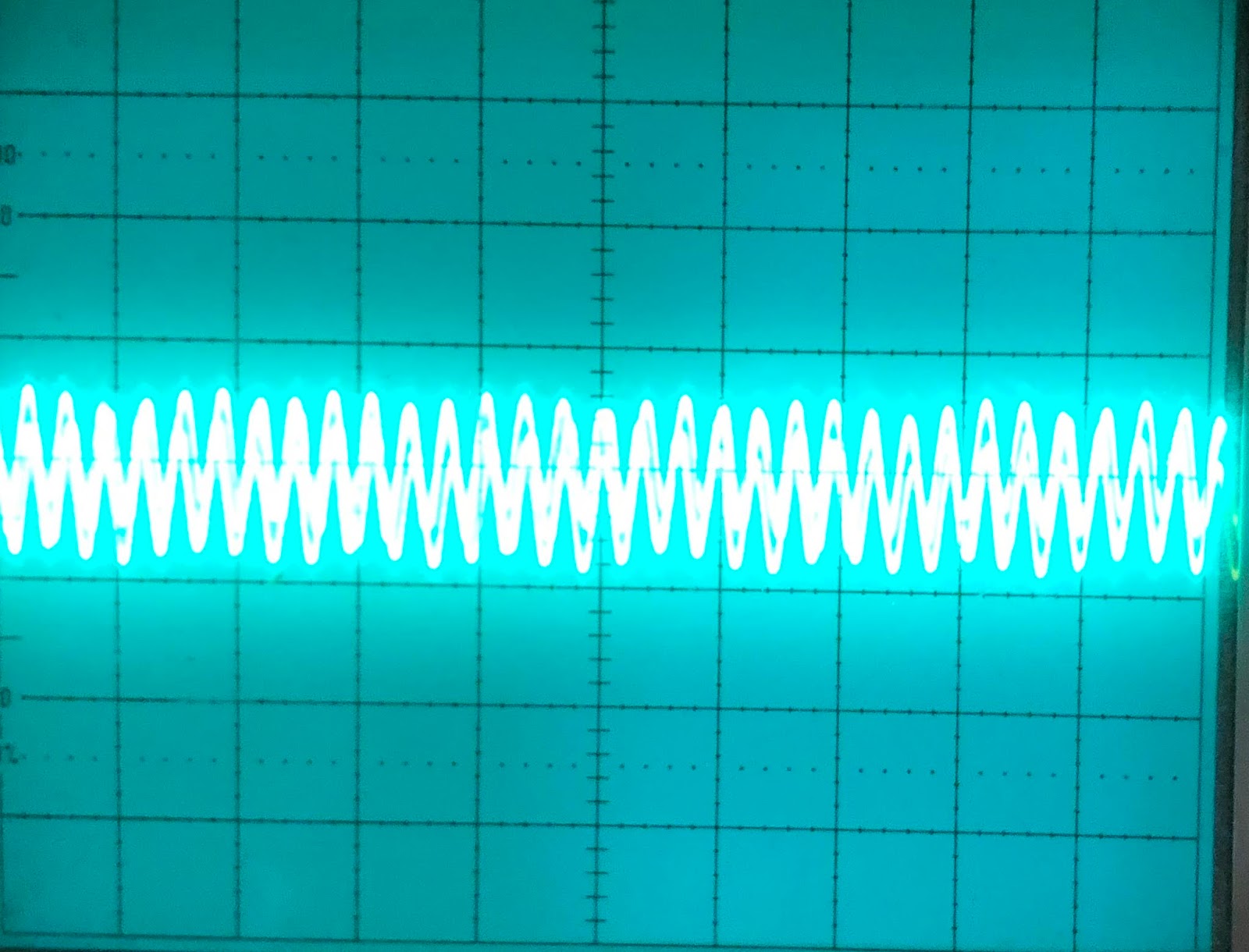
Now, both on the Juno and JP6 filters, this introduced a strange effect: Whenever I turned the cutoff down (in LP mode), or reduced the amplitude of the input, the output started ping-ponging between very high and very low. The filtered signal was still in there, but an offset with changing polarity was added:

Ping-ponging with a period of 6ms is introduced when feedback is increased

For the Juno filter, the feedback amp was very similar to the output VCA, and included the same 1uF AC-coupling cap. 

First, I thought this effect was due to the input to the feedback not being properly centered, so I introduced a trimpot as well. This had some effect, but only because it reduced the feeedback. I then tried removing the AC coupling cap in the feedback amp, and suddely the ping-ponging stopped.

I still have a large offset in the signal prior to the output amp, but this is mostly taken care of by the AC-coupling cap before the amp:

Top: Output before the output VCA AC-coupling cap when turning the feedback pot rapidly up and down. Bottom: The output. The spikes are caused by the AC-coupling cap doing its job. It takes around 400ms to properly settle.

It's a working concept but not entirely satisfying. I don't know what else to do at the moment, and when things don't change too rapidly this works ok.

To reduce the time the signal takes to settle, I can replace the 1uF cap with a 470nF one, that halves the settling time:

470nF cap gives 200ms settling time

Now, these examples are from setting a low cutoff frequency. We see the same with a low amplitude input, but then an additional effect appears:

A +/- 1.2V signal when the feedback is introduced. At high feedback the output suddely drops.


Not sure what causes this, and it is only at close to max feedback, but suddenly the output drops and changes shape. It looks like some kind of phase reversal (but maybe not the kind the TL07x is notorious for) as the feedback suddely attenuates the signal, but not sure what is going on. Here's a closeup:


Edit: My current theory is:

The max feedback in the current circuit is "unity" (or perhaps slightly more?), e.g. we feed a signal with the same amplitude as the input back from the output. This means that for every iteration, the signal will increase in strength, not going towards a stable point? Presumably, this can have some strange effects.

I'm also simulating the feeback at extreme values - I've changed the feedback CV range to 0-8V and use a 47k resistor in place of the 100k input for the feedback, this produces some very strange results in the simulation that I need to look closer into.

Edit 2: Look at this!

I managed to simulate an overdrive amount sweep - and it looks exactly like the output I see in the real circuit!

I set the overdrive CV to be equal to the number of seconds since simulation started (e.g. overdrive CV is 1V at 1s etc), so we can see that the output breaks down around 3.5V. 


As some of the op amps in my simulation does not have power rails, the ranges may be a bit different. Also, the signal is +/-2.5V, not +/-1.2V.

Oh, and how do one do voltage sweeps combined with transient analysis in LTSpice?

You replace the voltage source with a Behavioral Voltage source (BV), which has a formula of V=[...]. To get the current time use 'time', time is in seconds so V=time will do what happens here. Then run a normal Transient and make sure that the stop time is sufficiently large to capture what you want to see.

Edit 3:

I'm searching modwiggler to explain what I see. Here is a start:
 

Positive feedback causes oscillations:
https://modwiggler.com/forum/viewtopic.php?t=274218&hilit=filter+feedback+issue


Monday, January 1, 2024

Biasing cap and filter response

1uF

While looking for the reason why the filter output jumps frantically between +/- max when the cutoff is low or the input is close to zero when turning up distortion (spoiler: it's the biasing capacitor), I realised that I should have a closer look at what the output biasing/centering capacitor is actually doing to the filter's response. 

The cap is there to make sure the output is centered around 0, i.e. filter out any DC component (AC coupling the signal). The higher the capacitor, the longer the filter takes to change to 0V after an abrupt (DC) change. In the case of the jumping described above, I would like the change to settle as fast as possible, which means replacing the current 1uF cap with a smaller one, but what would that do to the output?

Looking online, it seems that the most common value of cap is 10uF. The Juno synths use 1uF. The cap in combination with a resistor/resistance creates a high pass filter with the cutoff frequency f=1/(2*PI*C*R). In my case, I have an 82k resistor immediately following the cap so I assume that this is R in the formula (the JP8 uses 100k and Juno 6 56k + a 20k trimmer).

The red line in the first plot here shows what our current 1uF cap does.

0.47uF

1uF 3dB
The 470uF cap clearly moves the cutoff frequency higher. Its -3dB point is at approximately 2.9Hz, compared to the 1.4Hz of the 1uFthe calculated values are 1.94Hz and 4.2Hz so 82k is at least close to the "real" resistance).


0.47uF at 20Hz
The human hearing is usually considered incapable of hearing frequencies of less than 20Hz. At this point the 0.47uF cap attenuates the signal by 90mdB. This in itself is not a lot, but it means that any sub-audible, ground shaking frequencies are filtered out. This may not be a problem as the equipment later in the chain may also have similar filtering, but it is something to think about.


10uF

In comparison, the 10uF cap gives a cutoff of less than 0.2Hz which is probably the reason why it's the more common choice.

0.047uF
I've seen some designs use a 47nF cap. This gives a -3dB cutoff at 370Hz which is a complete no-go combined with my 82k resistor.

Sunday, July 9, 2023

JP6 gain through cell 2

In the simulation, cell 2 outputs a +/- 2.6V signal when output from Cell 1 is 4V. This in turn arrives at the output as 3.1V and is overdriven to 4V with a nice rounded shape. 

Now, the output gain feedback resistor is 100k. Let's do some calculations.

LP and HP are tapped through 33k + 47k = 80k. That should give a gain of 1.25, which should give an output of 2.6 * 1.25 = 3.25.

The output of the BP requires a gain of 1.33 in cell1 in the simulation, and 1.5 on the breadboard, to be equal to the LP and HP outputs

That means a total gain of 1.25 * 1.33 = 1.66 (or 1.88 on the breadboard)

Thus, we need 100k / x = 1.66, x= 60k (or 53k for the breadboard).

For the direct output from cell 1, which is at 4V in the simulation, to get it to 3.1 requires a gain of 3.25/4 = 0.81, or a 125k input resistor. 

Now, wait a minute. Gain < 1 is generally not something we do, we usually do it by using a resistor divider. But let's not, let's rise the output level from 3.25 to 4 instead, meaning we only need unity gain for cell 1.

That gives us the input resistor for LP/HP as

gain = 4/2.6 = 1.54, R = 65k

and for BP

gain  = 1.33 * 1.54 = 2, R = 50k (and 1.5 * 1.54 = 2.3, r = 43.5)

Let's see what this does in the simulation:

Well, LP still looks good, at just a tad below 4V. Then, turning up overload to max fivces a slightly more distorted wave, but still cool, and with an amplitude of 5.1.

Now for another check, what happens with a 20Vpp signal. Does it distort?

It definitely does, but that's not because of the feedback, it's just how the circuit works.

We could get around this by using a 200k input resistor instead of a 100k, and then double the gain at the end of the circuit instead. We'll just have to try this to see how it affects both a 5V and 10V signal when doing distortion.

On breadboard

I tried sending a 5V signal through cell 2, and I get 3.23V on LP, 3.32V on HP and 2V on BP, meaning we need a gain around 1.6 for BP. 

To get all up to 5V at the output would require gains of
HP/LP: 5 / 3.23 = 1.54
BP: 5 / 2 = 2.5
and unity.

100k / 1.54 = 65k
100k / 2.5 = 40k

So a combination of 47k and 18k, and 22k and 18k is a good starting point.

Testing: 
LP: Near perfect 5V out
HP: Output is 5.2V, so a tiny bit too high
BP: Damn close to correct.


This means I will try the following for cell 2 in "production":
HP and LP: 47k +18k
BP: 22k + 18k
Direct: 82k + 18k

For cell 1 I will use 56k for everything, but BP is boosted by 1.5 using a 150k feedback and 100k input resistor


Next things to try on breadboard:
- overdrive
- no resistor pre-mux for cell 1
- swap cells to see if they behave similarly
- output vca.
- polaritites for output VCA and overdrive, see if we should modify cell circuit

See "Jupiter 6 filter - no VCA - 12V - JOVE trials -overdrive"


Monday, May 25, 2020

Little Phatty overload is just soft clipping

From the time I studied the Little Phatty to build my moog filter, I have wondered if the LP does pre-filter distortion of the signal or if it uses feedback for its overload.

From the Little Phatty schematics it is clear that overload is just soft clipping, and the circuit is extremely similar to what I did for my distortion with in-feedback-loop OTA :-D


The LP:

There are a couple of differences: The moog circuit uses both inputs of the OTAs, and also the same CV (though inverted) for both increasing the amount of distortion and reducing (?) the output gain. A nice trick to keep output at the same level I assume.

The overload CV also controls gain/attenuation of the filter output it seems.

UPDATE: I missed something - in addition to the soft clipping, the output from the distortion is fed back to the audio mixer, thus the distortion also has feedback.

Tuesday, March 31, 2020

Distortion (clipping)

Seems I can't stop working on my synth these days. There are two major parts missing from my synth voice cards: Digital playback and pre-filter distortion. I am not sure about the need for the last one, so I decided to build that first.

Googling distortion circuits I came across a resource that I have read long ago and forgotten about: Design your own distortion.

This page gives a great step by step introduction to two types of distortion: Hard and soft clipping. It also has some on filtering and tone control but it contains some errors (50nF cap in distortion does not give a lower frequency of 31Hz but 3.1kHz, the shown circuit will not give any distortion and indeed very little gain for frequences lower than 3.1kHz).

I decided to try simulating the circuit in LTSpice (with +/-15v supply lines) before breadboarding it, to get a feel of what it is doing.

Hard clipping

The hard clipping part of the circuit is easy. Two parallel diodes in reverse order from signal to ground after a buffer or similar that disconnects it from the input.

Hard clipping at around 750mV

What is going on? When the input signal, and thus the voltage across the diodes reaches the forward voltage drop of one of the diodes, it switches on, sinking the current to ground. This effectively cuts off the peaks of every wave cleanly. A fairly normal diode voltage drop is around 0.75V, meaning the signal is clipped at 0.75V. The amount of clipping is adjusted by attenuating the input (assuming a +/-5v input) to where you want the clipping to occur.

If one wants a higher clipping point it is also possible to connect diodes in series, going from 0.75V to 1.5V to 2.25V etc.

Hard clipping with series diodes, clips at around 1.5V


Soft clipping

This is slightly more involved. Soft clipping means that instead of brutally chopping off the wave tops, they are rounded off. Soft clipping can be achieved by placing two diodes in parallel / reverse order in the negative feedback loop of an op amp, parallel to the feedback resistor.

I first simulated inverting amplification instead of the non inverting "tube screamer" version on the web page because I could not get that one working due to the HP cutoff error in the article.


Here is what I think is going on, and why this is different to hard clipping:

When the voltage across the feedback resistor Rf is low, the diode will be turned off. Current only flows through Rf. Increasing the voltage (and thus current) gradually switches on the diode. Some of the current starts flowing through the diode while some still flows through the resistor.

Soft clipping currents - the original input current (red) is equal to the sum of the current through the resistor (blue) and diode (green). The diode only starts conducting after a while, but when it does almost all current goes through it.

Abiding to Ohms law, the opamp output voltage is still the current flowing through the resistor times the resistance, but as some of the current required to keep the two opamp inputs equal now flows through the diode, the output voltage is less than the input voltage (given a unity gain configuration where Rin = Rf).

As the input current increases, more and more current flows through the diode, and the amount of current flowing through the resistor flats out, cutting off the top of the input waves.


Another interesting thing to note is at what voltage the cut happens at is affected by the resistance of Rf. With a larger resistance, current starts flowing through the diode earlier (as its "resistance" is lower). Thus, the voltage across the resistor when it starts clipping is also lower, meaning the output is clipped more than with a lower value resistor.

Example values for a +/-1v input are clipped peaks at:

550mV for 1k,
450mV for 10k and
355mV for 100k.


A +/-5v input has peaks at 650mV and +/-15v peaks at 712mV (at 100k?)

Soft clipping with 1k resistor in feedback loop

Soft clipping with 10k resistor in feedback loop

Soft clipping with 100k resistor in feedback loop


Currents with 1k resistor, total current is 1mA

Currents with 10k resistor, total current is 100uA. A proportionally larger part of the input current goes through the diode (the diode "resistance" is still the same so it's easier for the current to go this way) and the output current is clipped earlier.

Currents with 100k resistor, total current is 10uA, an even larger part of the current goes through the diode


The non-inverting version probably works in the same way.

I first had issues getting the non-inverting circuit from Design your own distortion to work because of the HP cutoff error, but finally I found and was able to simulate a similar non-inverting circuit, this one:

https://electronics.stackexchange.com/questions/473989/need-help-designing-and-implementing-an-op-amp-based-distortion-circuit

Non inverting circuit, increased value of filter cap, meaning a lower high pass filter point distorts the wave.
The same circuit as above but without filter cap. The clipping part is more visible here.


The slight skewing is because of the cap in the feedback loop. Gain is (10k + 220) / 220 = 46

It also explains a very important thing: The guitar signal amplitude is 40mV, nothing near the 1-5V I've been experimenting with so far. Taking this into account I was able to simulate a +/-15v version of the original circuit, but WITHOUT the 50nF capacitor in series with the 1k input resistor on the positive terminal of the op amp, an the resistor connected to GND instead of the negative supply (in the original circuit it is connected to ground, but ground is the negative supply as this is a 9V circuit). See the filter section below for an explanation of why removing the 50nF cap was necessary (the cap value is simply wrong due to a calculation error in the article).

Further more, Rf must be much larger than 1k to get distortion, without this all the current flows through Rf and none through the diodes so no clipping happens. I've been working with 30k.

Working soft and hard clipping. The input (green) is multiplied by 31 to see how it matches (the non inverting opamp configuration here amplifies the input 31 times).

I have also simulated various types of diodes for the soft clipping circuit, more about this in a separate post.

Filtering

The webpage on top also talks a lot about filtering. The original article is about distortion for guitars and says that one should aim for keeping frequencies from 40Hz to 30kHz (NB: There is a serious error in the HP filter calculations in the article, see the end of this section). It may be different for a synth but that's a good starting point.

The article discusses high pass and low pass filtering in a non-inverting amplifier. The chosen circuit is often referred to as shelving filters elsewhere, it is not the most common circuit in examples on the web.

Shelving filters actually have two parts, the "normal" high or lowpass filter, and then a second part where it flattens out again at a lower or higher frequency with lower gain, but where the gain stays at this level instead of continuing to drop off, letting all frequencies below (for HP) or above (for LP) pass. - see http://www.linkwitzlab.com/filters.htm#5.

Here are the sub-circuits and formulas needed for calculating the 3dB points:

The full circuit (NB: Other component names than the original):


The second parts of the shelving filter: Both these have gain = 1. To find the frequencies, replace R1 in the HP formula with (R1 + R2), and R2 in the LP formula with (R1*R2) / (R1 + R2).

For example:

Given the values
R1 = 1kOhm
R2 = 10kOhm
C1 = 50nF
C2 = 470pF

For the HP filter:
HP filter frequency: 3.1kHz (Gain = 11)
Lower frequency: 290Hz (Gain = 1 for all freqs below this)

For the LP filter:
LP filter frequency: 33.9kHz  (Gain = 11)
higher frequency: 373kHz (Gain = 1 for all freqs above this)

PS: In the "Design your own distortion" article HP frequency capacitor selection calculation is wrong. 1 / (2 * PI * 1000 * 40) is not 0.039uF, it is 3.98uF. This explains my inability to get the distortion working without removing the cap during my simulation - I simulated using a 400Hz sine wave, this is well below the 3.1kHz HP cutoff, meaning it has unity gain and is not at all distorted.

In general, there is a lot of info about filtering missing from the "Design your own distortion" article. The Tube Screamer analysis at https://www.electrosmash.com/tube-screamer-analysis has a much better description, talking about how the filter frequencies are affected by changes in the gain of the distortion and how bass frequencies are passed undistorted (but also un-amplified).


When deciding on component values, one first chooses the gain, then calculate the necessary capacitors.

See also


https://www.premierguitar.com/articles/diode-stew-1
https://sound-au.com/articles/soft-clip.htm
https://anasounds.com/od-disto-fuzz-differences/
https://www.electrosmash.com/tube-screamer-analysis

Sunday, February 3, 2019

Moog Little Phatty - oscillator and filter, how does the output look

To get a feel of how my filter is performing, I took a closer look at the Moog Little Phatty, and how its output looks on the scope.

Waveforms

The LP does not have discrete selectable waveforms. Instead, it has a continously changeable waveform that starts as a triangle wave, goes through saw and sqare and then ends up as a pulse wave.

This is what it looks like when turning:


Here are the four variations that most closely resembles the four mentioned waveforms:


Pulse wave. Notice how it is no longer centered around 0V - instead, the TOP is at 0V.
There are two things to notice:

First of all, the wave is not straight, it curves slightly. The triangle wave is actually on its way to becoming a sine wave, and the saw wave is almost like a half sine with an abrupt but not instant fall to the bottom. These photos are taken at a rather high frequency, but the effect becomes even more pronounced as the frequency drops. This means that the perceived level of the triangle wave is significantly lower than that of the other waveforms, just like with a sine wave. It also probably introduces different overtones than the waveforms from a 'cleaner' waveshaper does, which may greatly affect the character of the synth. Interesting!

Second, the wave is not always centered around 0V. This is something I've wondered a lot about after looking at various service manuals - a lot of them use a capacitor to center the wave, which means that waves with uneven energy levels above and below 0V would end up not being sentered. This is clearly the case with the LP - look at the photo of the pulse wave above, it has its TOP at 0V. This is fine and inaudible as long as the output does not start clipping, and mixing multiple oscillators that are not synced would probably reduce the offset. Still, it's interesting to see that this is actually done in professional instruments. I worked hard on my waveshaper to prevent this, perhaps it's unnecessary.

Resonance and self oscillation amplitude

Here is a video of what happens when I turn on resonance with the cutoff set to max. I then gradually reduce the cutoff to introduce self oscillation:


As you can see, the amplitude is quickly reduced to less than 50%. Then, when adding self oscillation, the self oscillation has an amplitude closer to (but less than) the original signal. It never overpowers the original:

Original wave, no resonance

Full resonance and filter fully open

Cutoff turned down, filter is self oscillating
Resonance pot response

In my last post I explained how I found that the resonance CV for the juno filter definitely not was exponential, but not sure if reverse exponential (using a reverse log pot) or linear was the best. Here is how the LP responds:


All pics are taken with the cutoff slightly higher than middle. Self resonance becomes visible about when the pot pointing to the right. This is independent of cutoff, and is fairly similar to the linear pot in my Juno VCF circuit.


Oscillator mixing

The little phatty has two oscillators. I would expect mixing them to simply sum them up, but it seems the total is less than the sum. I did the summing by running two similar waveforms on both oscillators and synching oscillator 1 and 2. The sum reached it's peak with oscillator 1 at 100% and oscillator 2 at 50%, after this further summing only changed the shape of the output slightly. It seems to me that the synth does some soft clipping or similar, which becomes more apparent when using overload.


Overload

Overload increases the amplitude of the signal. At first it appeared that it only doubled the amplitude:


But when lowering the cutoff and then turning on overload, we see that the wave is heavily distorted:


Switching to a different waveform shows this even more. It seems that the actual amplification is much more than doubled, but that the Little Phatty uses something like a compander/limiter circuit to soft clip the output (or maybe not - it starts stretching long before the edges reach the peak) - see how the middle of the wave is much more amplified than the top/bottom:


Overloading a triangle wave:


Overloading a saw wave: