Showing posts with label overload. Show all posts

Sunday, January 28, 2024

Moog overload circuit

Since my previous posts I've gotten some feedback from the Modwiggler forums about the breakdown I see when overdrive/feedback is high. The answer is that this is normal for positive feedback, which I guess is ok. I've since chosen to abandon the per-filter overdrive in place of my own pre-filter distortion.

I've taken a closer look at the Little Phatty (LP)/Slim phatty overload circuit to see how the professionals do it, and to see if the circuit exhibits the same behaviour.

The LP overload is a combination of two things - first, a voltage controlled distortion that puts an OTA in the negative feedback of an op amp, basically acting as a voltage controlled resistor. This is the same solution I'm using for my distortion. But then it also has a second OTA that feeds the output back to the oscillator/source mixer. This is positive feedback, much like what I'm doing on the filters.


Overload circuit uses two OTAs

In addition to the two OTAs in the overload circuit, the overload CV controls a VCA after the filter, more about this towards the end.

LP CV generation

The CVs on the LP is generated by a DAC8581. This is a bipolar DAC that outputs +/- a ref voltage. The reference voltage is 4.096V. The voltage is then fed through an op amp gain circuit, which has a trimmer in the negative feedback. I've simulated this, and at the extremes the trimmer has an output of around 4.7 to 5.5V. Thus, I assume the trimmed output is supposed to be +/-5V, at least this makes it easier to reason about the later parts of the circuit.


Oscillator VCA

Each oscillator has a VCA controlling the level into the source mixer. At +5V VCA CV the output sees approximately unity gain.


OSC1 VCA cv -5 to 5V vs output


OSC1 VCA input vs output, approximately unity gain

Distortion

The distortion in the circuit is done using two diodes in the feedback of an op amp. This is a very common scheme and gives soft clipping. An opamp controls the feedback amount. 


Approx 3 x gain from OTA in distortion op amp, feedback to mixer disconnected


-5 to 5v overload CV. Unity gain in distortion circuit when CV is -5, feedback to mixer disconnected  

Feedback

The output from the distortion circuit is fed back to the source mixer (and then gets distorted again and again and... You get it). This increases the distortion and also the amplitude of the signal fed into the filter.

-5 to 5v overload CV, feedback to mixer connected


Breakdown

As for the big question - do we see the same issue here as in my filter-overdrive circuits? Yes we do! At small input amplitudes, < +/-0.6V input, we get the same breakdown/railing. It's kind of comforting to see that there's not something magical going on in the Moog overload. The reason it doesn't show up earlier is, I assume, that the amount of feedback is not as high so the effect appears much later.


0.4Vpp sine is railing


5Vpp sine is ok


Post filter VCA


As mentioned at the beginning of the post, the overload CV also controls an output VCA. At -5V overload CV the VCA has a gain of 1.6. Increasing CV to 5V gives a gain of 2.3, adding some additional oomph to the signal. Not sure exactly why they do this. Also, when looking at the overload in a previous post I did, it does not look like overload increased the signal amplitide by much. I really expected this VCA to attenuate the signal when overload increased, but it doesn't seem to be the case

Filter output VCA - from 1.6 x gain to 2.3 x


Friday, July 17, 2020

Distortion circuit mostly ready for production

I've finished v1 of the distortion circuit PCB:


I still have to double check the schematics, I've done so many silly errors lately...

The board has switchable soft/hard clipping, and CV adjustable distortion and output gain.


Little/slim phatty distortion/overload

Before I send this one to production, I will breadboard and try out the distortion circuit from the little phatty:


It looks fairly similar, but the output, labeled audio_sum, is actually connected to a point BEFORE the input, labeled mixer_out here. This means it actually feeds the result back to the start, not only distorting it (there is only buffer and voltage divider between though). Also, the overload_cv controls an additional output VCA located after the filter. I can't tell from the circuit diagram what the gain / level is at various points of the circuit so I will simulate this.


Monday, May 25, 2020

Little Phatty overload is just soft clipping

From the time I studied the Little Phatty to build my moog filter, I have wondered if the LP does pre-filter distortion of the signal or if it uses feedback for its overload.

From the Little Phatty schematics it is clear that overload is just soft clipping, and the circuit is extremely similar to what I did for my distortion with in-feedback-loop OTA :-D


The LP:

There are a couple of differences: The moog circuit uses both inputs of the OTAs, and also the same CV (though inverted) for both increasing the amount of distortion and reducing (?) the output gain. A nice trick to keep output at the same level I assume.

The overload CV also controls gain/attenuation of the filter output it seems.

UPDATE: I missed something - in addition to the soft clipping, the output from the distortion is fed back to the audio mixer, thus the distortion also has feedback.

Sunday, March 3, 2019

Moog VCF overload reference voltage

The filter starts overloading right after +/-5V input. The input summer has a gain of -0.15 (15k/100k), so after the summer the voltage is +/-0.75V.

By using a resistor divider consisting of a 10k and a 1.8k resistor between 5V and GND, the center will be at 0.763V.

Moog filter with overload


Not much to say really, added overload feedback w/vca. Specified single/multiturn pots. Almost ready for computer control.

Sunday, February 3, 2019

Moog Little Phatty - oscillator and filter, how does the output look

To get a feel of how my filter is performing, I took a closer look at the Moog Little Phatty, and how its output looks on the scope.

Waveforms

The LP does not have discrete selectable waveforms. Instead, it has a continously changeable waveform that starts as a triangle wave, goes through saw and sqare and then ends up as a pulse wave.

This is what it looks like when turning:


Here are the four variations that most closely resembles the four mentioned waveforms:


Pulse wave. Notice how it is no longer centered around 0V - instead, the TOP is at 0V.
There are two things to notice:

First of all, the wave is not straight, it curves slightly. The triangle wave is actually on its way to becoming a sine wave, and the saw wave is almost like a half sine with an abrupt but not instant fall to the bottom. These photos are taken at a rather high frequency, but the effect becomes even more pronounced as the frequency drops. This means that the perceived level of the triangle wave is significantly lower than that of the other waveforms, just like with a sine wave. It also probably introduces different overtones than the waveforms from a 'cleaner' waveshaper does, which may greatly affect the character of the synth. Interesting!

Second, the wave is not always centered around 0V. This is something I've wondered a lot about after looking at various service manuals - a lot of them use a capacitor to center the wave, which means that waves with uneven energy levels above and below 0V would end up not being sentered. This is clearly the case with the LP - look at the photo of the pulse wave above, it has its TOP at 0V. This is fine and inaudible as long as the output does not start clipping, and mixing multiple oscillators that are not synced would probably reduce the offset. Still, it's interesting to see that this is actually done in professional instruments. I worked hard on my waveshaper to prevent this, perhaps it's unnecessary.

Resonance and self oscillation amplitude

Here is a video of what happens when I turn on resonance with the cutoff set to max. I then gradually reduce the cutoff to introduce self oscillation:


As you can see, the amplitude is quickly reduced to less than 50%. Then, when adding self oscillation, the self oscillation has an amplitude closer to (but less than) the original signal. It never overpowers the original:

Original wave, no resonance

Full resonance and filter fully open

Cutoff turned down, filter is self oscillating
Resonance pot response

In my last post I explained how I found that the resonance CV for the juno filter definitely not was exponential, but not sure if reverse exponential (using a reverse log pot) or linear was the best. Here is how the LP responds:


All pics are taken with the cutoff slightly higher than middle. Self resonance becomes visible about when the pot pointing to the right. This is independent of cutoff, and is fairly similar to the linear pot in my Juno VCF circuit.


Oscillator mixing

The little phatty has two oscillators. I would expect mixing them to simply sum them up, but it seems the total is less than the sum. I did the summing by running two similar waveforms on both oscillators and synching oscillator 1 and 2. The sum reached it's peak with oscillator 1 at 100% and oscillator 2 at 50%, after this further summing only changed the shape of the output slightly. It seems to me that the synth does some soft clipping or similar, which becomes more apparent when using overload.


Overload

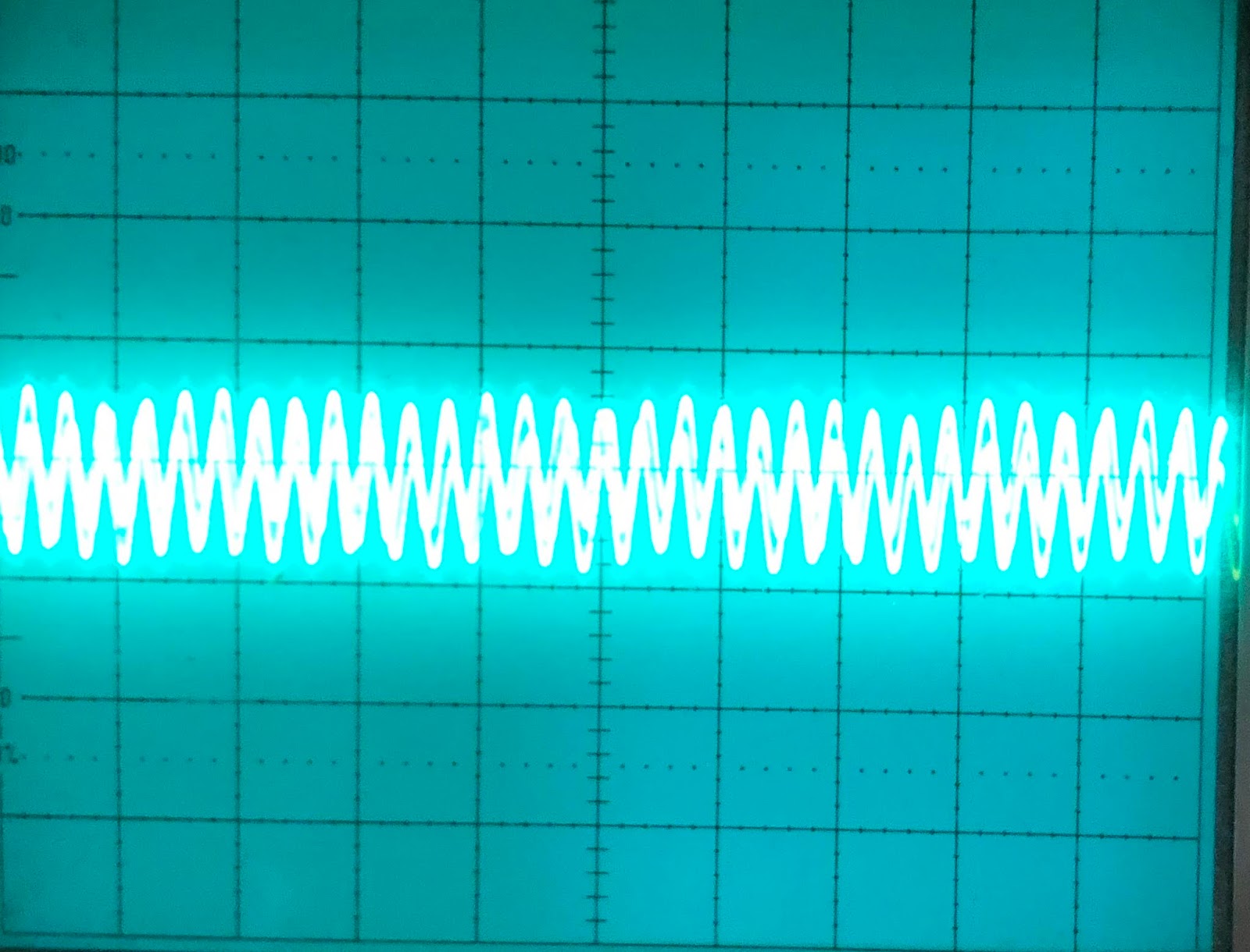
Overload increases the amplitude of the signal. At first it appeared that it only doubled the amplitude:


But when lowering the cutoff and then turning on overload, we see that the wave is heavily distorted:


Switching to a different waveform shows this even more. It seems that the actual amplification is much more than doubled, but that the Little Phatty uses something like a compander/limiter circuit to soft clip the output (or maybe not - it starts stretching long before the edges reach the peak) - see how the middle of the wave is much more amplified than the top/bottom:


Overloading a triangle wave:


Overloading a saw wave: