Googling distortion circuits I came across a resource that I have read long ago and forgotten about: Design your own distortion.
This page gives a great step by step introduction to two types of distortion: Hard and soft clipping. It also has some on filtering and tone control but it contains some errors (50nF cap in distortion does not give a lower frequency of 31Hz but 3.1kHz, the shown circuit will not give any distortion and indeed very little gain for frequences lower than 3.1kHz).
I decided to try simulating the circuit in LTSpice (with +/-15v supply lines) before breadboarding it, to get a feel of what it is doing.
Hard clipping
The hard clipping part of the circuit is easy. Two parallel diodes in reverse order from signal to ground after a buffer or similar that disconnects it from the input. |
| Hard clipping at around 750mV |
What is going on? When the input signal, and thus the voltage across the diodes reaches the forward voltage drop of one of the diodes, it switches on, sinking the current to ground. This effectively cuts off the peaks of every wave cleanly. A fairly normal diode voltage drop is around 0.75V, meaning the signal is clipped at 0.75V. The amount of clipping is adjusted by attenuating the input (assuming a +/-5v input) to where you want the clipping to occur.
If one wants a higher clipping point it is also possible to connect diodes in series, going from 0.75V to 1.5V to 2.25V etc.
 |
| Hard clipping with series diodes, clips at around 1.5V |
Soft clipping
This is slightly more involved. Soft clipping means that instead of brutally chopping off the wave tops, they are rounded off. Soft clipping can be achieved by placing two diodes in parallel / reverse order in the negative feedback loop of an op amp, parallel to the feedback resistor.I first simulated inverting amplification instead of the non inverting "tube screamer" version on the web page because I could not get that one working due to the HP cutoff error in the article.

Here is what I think is going on, and why this is different to hard clipping:
When the voltage across the feedback resistor Rf is low, the diode will be turned off. Current only flows through Rf. Increasing the voltage (and thus current) gradually switches on the diode. Some of the current starts flowing through the diode while some still flows through the resistor.
 |
| Soft clipping currents - the original input current (red) is equal to the sum of the current through the resistor (blue) and diode (green). The diode only starts conducting after a while, but when it does almost all current goes through it. |
Abiding to Ohms law, the opamp output voltage is still the current flowing through the resistor times the resistance, but as some of the current required to keep the two opamp inputs equal now flows through the diode, the output voltage is less than the input voltage (given a unity gain configuration where Rin = Rf).
As the input current increases, more and more current flows through the diode, and the amount of current flowing through the resistor flats out, cutting off the top of the input waves.
Another interesting thing to note is at what voltage the cut happens at is affected by the resistance of Rf. With a larger resistance, current starts flowing through the diode earlier (as its "resistance" is lower). Thus, the voltage across the resistor when it starts clipping is also lower, meaning the output is clipped more than with a lower value resistor.
Example values for a +/-1v input are clipped peaks at:
550mV for 1k,
450mV for 10k and
355mV for 100k.
A +/-5v input has peaks at 650mV and +/-15v peaks at 712mV (at 100k?)
 |
| Soft clipping with 1k resistor in feedback loop |
 |
| Soft clipping with 10k resistor in feedback loop |
 |
| Soft clipping with 100k resistor in feedback loop |
 |
| Currents with 1k resistor, total current is 1mA |
 |
| Currents with 10k resistor, total current is 100uA. A proportionally larger part of the input current goes through the diode (the diode "resistance" is still the same so it's easier for the current to go this way) and the output current is clipped earlier. |
 |
| Currents with 100k resistor, total current is 10uA, an even larger part of the current goes through the diode |
The non-inverting version probably works in the same way.
I first had issues getting the non-inverting circuit from Design your own distortion to work because of the HP cutoff error, but finally I found and was able to simulate a similar non-inverting circuit, this one:
https://electronics.stackexchange.com/questions/473989/need-help-designing-and-implementing-an-op-amp-based-distortion-circuit
The slight skewing is because of the cap in the feedback loop. Gain is (10k + 220) / 220 = 46
It also explains a very important thing: The guitar signal amplitude is 40mV, nothing near the 1-5V I've been experimenting with so far. Taking this into account I was able to simulate a +/-15v version of the original circuit, but WITHOUT the 50nF capacitor in series with the 1k input resistor on the positive terminal of the op amp, an the resistor connected to GND instead of the negative supply (in the original circuit it is connected to ground, but ground is the negative supply as this is a 9V circuit). See the filter section below for an explanation of why removing the 50nF cap was necessary (the cap value is simply wrong due to a calculation error in the article).
Further more, Rf must be much larger than 1k to get distortion, without this all the current flows through Rf and none through the diodes so no clipping happens. I've been working with 30k.
https://electronics.stackexchange.com/questions/473989/need-help-designing-and-implementing-an-op-amp-based-distortion-circuit
 |
| Non inverting circuit, increased value of filter cap, meaning a lower high pass filter point distorts the wave. |
 |
| The same circuit as above but without filter cap. The clipping part is more visible here. |
The slight skewing is because of the cap in the feedback loop. Gain is (10k + 220) / 220 = 46
It also explains a very important thing: The guitar signal amplitude is 40mV, nothing near the 1-5V I've been experimenting with so far. Taking this into account I was able to simulate a +/-15v version of the original circuit, but WITHOUT the 50nF capacitor in series with the 1k input resistor on the positive terminal of the op amp, an the resistor connected to GND instead of the negative supply (in the original circuit it is connected to ground, but ground is the negative supply as this is a 9V circuit). See the filter section below for an explanation of why removing the 50nF cap was necessary (the cap value is simply wrong due to a calculation error in the article).
Further more, Rf must be much larger than 1k to get distortion, without this all the current flows through Rf and none through the diodes so no clipping happens. I've been working with 30k.
 |
| Working soft and hard clipping. The input (green) is multiplied by 31 to see how it matches (the non inverting opamp configuration here amplifies the input 31 times). |
I have also simulated various types of diodes for the soft clipping circuit, more about this in a separate post.
Filtering
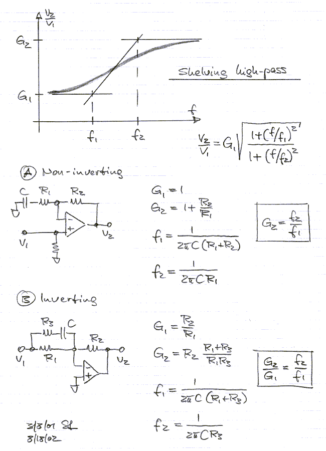
The webpage on top also talks a lot about filtering. The original article is about distortion for guitars and says that one should aim for keeping frequencies from 40Hz to 30kHz (NB: There is a serious error in the HP filter calculations in the article, see the end of this section). It may be different for a synth but that's a good starting point.The article discusses high pass and low pass filtering in a non-inverting amplifier. The chosen circuit is often referred to as shelving filters elsewhere, it is not the most common circuit in examples on the web.
Shelving filters actually have two parts, the "normal" high or lowpass filter, and then a second part where it flattens out again at a lower or higher frequency with lower gain, but where the gain stays at this level instead of continuing to drop off, letting all frequencies below (for HP) or above (for LP) pass. - see http://www.linkwitzlab.com/filters.htm#5.
Here are the sub-circuits and formulas needed for calculating the 3dB points:
The full circuit (NB: Other component names than the original):

The second parts of the shelving filter: Both these have gain = 1. To find the frequencies, replace R1 in the HP formula with (R1 + R2), and R2 in the LP formula with (R1*R2) / (R1 + R2).
For example:
Given the values
R1 = 1kOhm
R2 = 10kOhm
C1 = 50nF
C2 = 470pF
For the HP filter:
HP filter frequency: 3.1kHz (Gain = 11)
Lower frequency: 290Hz (Gain = 1 for all freqs below this)
For the LP filter:
LP filter frequency: 33.9kHz (Gain = 11)
higher frequency: 373kHz (Gain = 1 for all freqs above this)
PS: In the "Design your own distortion" article HP frequency capacitor selection calculation is wrong. 1 / (2 * PI * 1000 * 40) is not 0.039uF, it is 3.98uF. This explains my inability to get the distortion working without removing the cap during my simulation - I simulated using a 400Hz sine wave, this is well below the 3.1kHz HP cutoff, meaning it has unity gain and is not at all distorted.
In general, there is a lot of info about filtering missing from the "Design your own distortion" article. The Tube Screamer analysis at https://www.electrosmash.com/tube-screamer-analysis has a much better description, talking about how the filter frequencies are affected by changes in the gain of the distortion and how bass frequencies are passed undistorted (but also un-amplified).
When deciding on component values, one first chooses the gain, then calculate the necessary capacitors.
See also
https://www.premierguitar.com/articles/diode-stew-1
https://sound-au.com/articles/soft-clip.htm
https://anasounds.com/od-disto-fuzz-differences/
https://www.electrosmash.com/tube-screamer-analysis