Showing posts with label pink noise. Show all posts

Sunday, May 24, 2020

Noise tested


I tested the first board tonight, the triple noise. Two external parts are needed, a 2N3904 with the collector unconnected, the base connected to GND and the emitter connected to IN, and a 50k trimpot for adjusting the gain of the input.

It works perfectly. Rainy white, oceany pink and deep, rumbling red noise. Mmmm... I breadboarded this back in 2017 and had a lot of fun playing around with it with my then 3 year old daugter. "Daddy, can we go listen to the rain?"


Friday, September 22, 2017

Alesis Andromeda A6

While searching for noise samples to compare my breadboarded noise against, I had a look at the Andromeda A6 circuit diagram. It is fun to study what the big guys think are good designs and I've picked up a few ideas already. I will probably post more as I go anlong.

My first findings

Separate center reference voltage

The A6 seems to use a reference voltage, PMID/PDMID in place of ground whenever ground would be expected on any of the inputs of an opamp. My guess is that PMID/PDMID means Power Middle/Power Digital Middle or something like that, as ground in these places would normally be the center of the wave.

The PxMID originates with a 5V voltage regulator. I've calculated PxMID to be 2.05V. The A6 uses +/- 12V internally, with an offset of +2V this means that any positive amplitude is reduced to +10V minus any opamp limitations.

The PMID line is littered with bypass caps. I assume that by using a separate, well regulated reference voltage, one may get rid of some noise from other components, and also that its hard to get 0V from a regulator, thats why it's 2.05V (?).

Noise


The A6 has most of its analog circuitry inside a bunch of ASICs. The noise section however, is discrete. Only one noise source is used for all voices and it supplies white, pink and red noise.

The noise source seems fairly standard, it is based around a zener diode (which is the same technique as using a transistor without connecting the collector). The pink noise filter seems to be a true pink noise approximation (3dB/oct) as it uses a multiple filter sections in the same fashion as Elliot Sound Products. It is not entirely similar as it has the filter sections connected to between the positive input and ground, whereas the Elliot version have them in the feedback loop, but I assume this is only because the A6 one is a non-inverting filter and the Elliot an inverting filter. All noise outputs are connected to an inverting amp which also adds the PMID reference and acts as a low pass filter with cutoff at 493Hz.

Analog pots


All analog pots (that are read digitally) have 10nF caps across them - I assume this is to stabilize values or prevent that noise from one pot falsely triggers another one. 8 5kOhm pots are multiplexed through one CD4051 mux.

FX bus


The FX send has both positive and negative sends that are inverted versions of each other. Not sure if this means that it uses a balanced bus but it could be likely. Further investigation necessary :-D

Master volume


Master volume is a physical pot connected directly in the audio path, no VCA is used. No master volume saving is possible which makes sense.

Monday, September 11, 2017

Noise research

I intend for the XM8 to have noise as a waveform for both oscillators, and also to be able to switch between various 'colors' of noise. At the very least, white and pink noise should be present, possibly even red. But what exactly does this mean?

White noise is noise where the signal has equal intensity at all frequencies. In the synth world, it is commonly generated by using a transistor with one leg disconnected.

Pink noise is a signal where each octave carries the same amount of noise energy. But how is this achieved in practice?

According to Wikipedia, pink noise falls off at 3dB per octave. To get pink noise one filters white noise through a filter with 3dB/octave drop off.

Problem is, most basic active low pass filter has a 6dB drop off (which would actually give us red noise if used). So how may this be solved?

This page shows one method - use multiple filter sections to approximate a 3dB filter with a flat response. The more sections the better, but even four sections is pretty good for a 20-20 000kHz signal.

As a side note - the same page mentions NP capacitors, bipolar electrolytics, and says that film capacitors cannot replace them - this is interesting information as I've stumbled across NP in other circuits.

A similar approach seems to be in use on this page, which is a modification for the Sequential Circuits Pro One. It uses fewer sections (two?) and has an additional cap (C3).

But how does one calculate the frequency of each section?

In a normal active low pass filter (6dB), the frequency is 1/(2*PI*R2*C) and the gain is -R2/R1 where R2 is the resistor in the feedback loop.

It seems that the same holds true for each section in the multi section filter. For example:

1/6.28*100nF*1MOhm) = 1.59Hz
1/6.28*33nF*330kOhm) = 14.6Hz
...
which matches the frequencies next to the sections.

This would mean that the lower section of the Pro one filter is 338.8Hz, but the rest - the 270k and 3.3n combined gives us a 268.1Hz filter which seems a bit strange - however, I'm not sure this is the way to calculate the combined frequencies.

As for the gain, if the same formula as before is correct, it would be -270k/15k = -18.

The pink noise filter in the pro one matches the inverting shelving low pass filter found on this page. However, the only formula, found in the gif, is missing the lone cap in the feedback circuit.

Funny enough, the same filter topology is found in the BOSS CE-2 pedal's de-emphasis filter :). The de-emphasis filter reduces treble, which of course means it is a low pass filter of sorts. :)

On that page, the circuit is fully explained. When calculating the frequencies, the lone cap is omitted. It says that it is an LP of some sort but it is not essential when calculating the shelving frequencies.

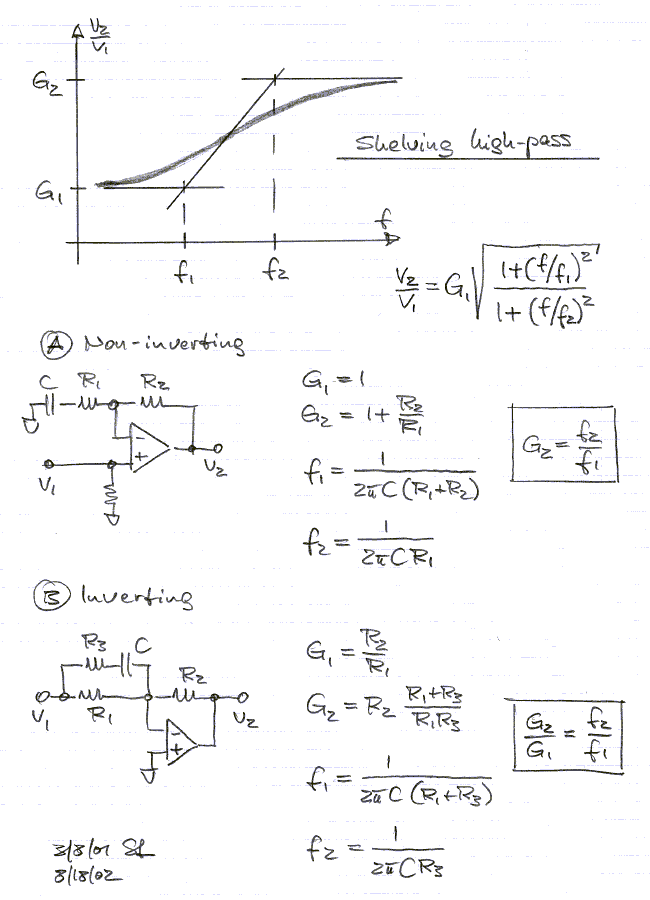
The filter right after the transistor in the pro one circuit is a simple non-inverting HP filter. C2 and U1b forms a shelving HP filter like this.

The first filter in the Ray Wilson Noise Cornucopia is a simplified non-inverting amplifier filter as shown here and here. Its gain is 1 + R10/R9 (=48), the frequency is 1/(2*PI*R10*C4), or approx 34kHz.

ERROR: det er et lowpass non inverting shelving filter.