Showing posts with label PIC32. Show all posts

Thursday, July 23, 2020

PCM player, DAC, PIC32MX and I2S

I have multiple options for a wave player/sampled attack/wavetable oscillator.

- I can add a DAC to the Voice controller and control it directly there - using a I2S Audio DAC will probably give a very high audio quality

- I can make a separate board with the same DAC, an extra MCU and external memory

- I can try to use the DCOs - they already have a 16bit DAC and I think I have exposed enough SPI pins to make it possible to access external SPI memory. This is the cheapest option but the sound quality must be tested.

In any case, when making the Voice board I should leave room for an optional wave card. It doesn't need its own VCA as the DAC should be good enough for volume control as well.


PIC32 and I2S Dac

It seems most Audio DACs these days use I2S for communicating with the host. The PIC32MX (and other low-end PIC MCUs) don't have I2S support built in, but here is something that seems to make it work:

https://www.aidanmocke.com/blog/2018/11/22/i2s/

https://hackaday.io/project/28965-pic32mx-music-box-with-fm-synthesis-and-i2s-dac

https://tutorial.cytron.io/2017/08/13/i2s-pic32mxmz-introduction/


DAC in general

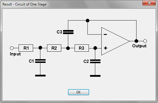
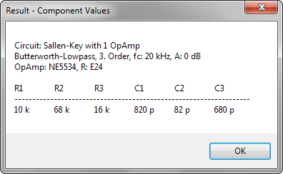
DACs need a reconstruction filter to remove unwanted frequencies. Here is an example that claims to be good:

https://www.analogfilters.com/high-quality-reconstruction-lowpass-filter-for-digital-audio/

Circuit

Components

https://www.softwaredidaktik.de/active-filters/download/

Sunday, March 26, 2017

DCO: SPI and DAC accuracy

A few compromises have to be made when making the DCO. There are however a few things that must be done right.

First of all, we cannot afford to lose any input commands. This will put the SPI input buffer in an unknown state, possibly locking up the DCO.

With this in mind, we can do a few calculations.

First of all - each frequency update is based on a 16bit integer. The SPI buffer is only 8 bits long, so two bytes must be transferred. Each transfer triggers an interrupt, and that interrupt must copy the transferred byte from the SPI buffer to somewhere else before the next byte arrives.

Fortunately, the SPI buffer is, as it says, buffered. This means that it is not written until the last bit of the byte is received. In addition, there is a short delay between bytes.

As an example, when running the SPI bus at 200kHz, a byte is 40uS long. The delay between two bytes is 7.5uS (when output from node.js on a Raspberry PI).

Running the MCU at 20MHz we have an instruction clock of 5MHz, and each instruction takes 0.2uS. This means that with a 200kHz SPI bus and 20MHz clock, we have 237 instruction cycles to handle a received byte.

This is of course much more than we need - as long as the interrupt handler triggers immediately. But for the DCO to be as accurate as possible, we have given priority to the timer that sets the output wave period. The SPI interrupt will be blocked if a timer interrupt has been received and will not be treated until the timer interrupt handler returns. Thus, we have to make sure the time it takes to enter the timer interrupt handler, do whatever it needs to do, return from the handler and then enter the SPI (low priority) interrupt handler, takes less than 237 instructions - if not, we may be inside the timer interrupt handler when the next SPI byte arrives and we'll lose the previous byte.

This sounds all good, right? The time it takes to reset the timer is not that long. Well, we do actually have a problem. If we are to both reset the timer AND change the DAC value (that controls the current that charges the integrator capacitor making the saw wave), we run into trouble. The DAC is written to using SPI, and we have to write three bytes to set it. Unless the DAC SPI runs at several MHz, we do not have time to write to it within the 47uS we have available. In simple terms, we cannot write to the DAC inside the interrupt handler.

So what is the consequence of this? 

The only other place to write to the DAC is inside the main program loop. As we will be at an arbitrary place in the code when a timer interrupt triggers, we will get a delay from when the timer triggers to where the DAC update call is found (+ the time spent writing to the DAC).

To reduce the maximum delay, we may check if a DAC update has been requested and update the DAC at several spots in the main loop.

But how big is the consequence of delaying the DAC?

At 200kHz, updating the DAC takes approximately 135uS = 675 instruction cycles. This delay is unavoidable.

The longest single method within the main loop, recalculating the frequency, takes 723 cycles. If we break this up into 5 intervals, we'll add around 150cycles to the maximum delay, which will then be around 825 cycles or 165uS.

What does this mean?

It means that for 165uS, the DAC will output the wrong voltage, and the capacitor will charge too fast or too slow. If it charges too slow, the capacitor will be at less than 5V when the charging is reset by the period timer. If it charges too fast, it will be at more than 5V. But how much?

Let's look at the two extremes:

Going from 16.5Hz to 20kHz

Here, the DAC will have a very low charge current. The period at 20kHz is 50uS. This means that for a little more than three periods, the charging will be way too low, in fact probably so low that the wave will look completely flat. However, this is only for 3 of 20.000 cycles within a second. Question is if it is audible.

Going from 20kHz to 16.5Hz

The DAC will have a very high charge current. It charges at the same level as when the frequency is 20kHz, which means that after 50uS, the output value is 5V and after 150uS it has reached 15V (but the buffer opamp or other parts of the circuit probably saturates, keeping the maximum at around 14.3V. The cap stays at this level for one full charging cycle, around 61mS. This is not a very ideal situation.

This is of course in the extreme cases. Most often the change in pitch will be small, but a few octaves are still likely.

What can be done to remedy this?

1) Increased DAC SPI speed - pushing the speed to 2MHz will reduce the write delay to 13.5uS, with a total of 43.5uS including the delay before we reach the reset DAC code. This is if the MCU and DAC can handle the increased SPI speed

2) Increase the MCU speed from 20MHz to 32MHz - this will reduce the maximum time before the DAC write is started from 30uS to 18.75uS (as each instruction now takes 0.125uS instead of 0.2uS.

3) Check more often if we need to update the DAC, further reducing the maximum time before the DAC is written to

4) If the DAC SPI speed is sufficiently high, put the write back into the interrupt routine, removing the delay before a write altogether.

If 1) is possible, and the rest of the timer interrupt handler takes less than 47.5uS - 13.5uS = 34uS, 4) is certainly the best option.


Input SPI speed

We chose 200kHz as the SPI speed at the start of this post. At this speed, 16 bytes will take 47.5uS to transfer (inc delay between bytes), giving an effective transfer rate of 21kB/s.  The Xonik M8 voice controller runs at less than 4k updates/second, so this is sufficient for updating tree DCOs at that rate. The PIC32 has a multi-byte SPI buffer, so we may actually write all bytes to the SPI buffer and forget about them, leaving the voice card MCU to do other duties while the buffer is written (though we have to write to the separate DCOs one at the time as the chip select lines must be changed between the DCO writes.

To further improve the performance of the main MCU (and reduce the delay between when a frequency update is requested and a new frequency is visible on the output), we should calculate the maximum time spent in the period timer interrupt handler and optimize the SPI speed such that the time spent transferring a byte is just barely longer than this.


Maximum delay

The maximum delay from a byte request has been received at the main voice controller to it is visible at the DCO input may be calculated as follows:

2 x matrix calculation time
+ 2 x byte transfer time
+ 1 x transfer delay
+ 1 x time spent calculating new frequency params
+ 1 x delay writing to timer registers
+ 1 x time that must be left for an update
+ 1 x longest cycle time
+ 1 x time within period interrupt handler
+ 1 x maximum delay before DAC write starts
+ 1 x DAC write time.

2 x matrix calc time because the command may arrive just after a calc has started and be written at the end of a calc update


Update: SPI and DAC speeds

The MAX5216 SPI can run at 50Mhz. The PIC SPI runs at maximum Fosc/4, which equals 5MHz with a 20MHz crystal, 8MHz with a 32Mhz. In any case, transferring 24 bits takes approx 27 instruction cycles, so setting the DAC in the interrupt routine is well within what is feasible. Thus, the delay from period start to the DAC is set is 27 * 0.125uS = 3.4uS + any cycles between the timer reset and the call to set the DAC - 7 cycles + the time it takes to call the SPI function - an estimate may be 40 cycles = 5uS in total (at 32MHz).

This means that in the case of a too-high charging current, the cap will be charged at max for about 1/10th of the charge time at 20kHz, contributing about 0.5V too much to the end result (5.5V instead of 5V). This is probably tolerable.

Similarly, the whole interrupt function will take 33 cycles (timer) + 40 cycles (DAC). Add 10 cycles to enter and store the SPI byte and the total is 83 cycles or 10.4uS. Transmission speed will then have to be more than 1.3uS per bit, which gives a max SPI speed of 769kHz (at 32MHz)

Update 2:

The only times we should have to update the charging current will be right after we have calculated and set a new frequency. For most frequencies, this update will happen right after an SPI write (for low frequencies we will get a delay, though). If we keep the DAC update outside of the interrupt handler, we will still normally not be inside the calculation routine for a new frequency when the interrupt returns, so the delay between timer update and DAC update will be minimal. We may still encounter a large delay as it may take up to one period from frequency calculation to the frequency has been set. If SPI bytes arrive faster than this (as they most likely will if the main controller runs at 2-4kHz), we may still be inside the calculation routine.

By moving the DAC update we'll shorten the delay to 43 cycles = 5.38uS, giving us a bit time of 0.673uS and a max SPI speed of 1.49MHz (at 32MHz clock speed)

Ultimately it all comes down to what is most important - a high SPI speed to minimize the time the master spends writing or a short delay before the DAC is set to assure a high max voltage accuracy.

As mentioned previously, we may use the multi-byte SPI buffer on the PIC32 based voice controller, so the exact write speed is not all that important (as we do writes as fire-and-forget) but faster is still better - we will have to write some special code that writes to the DCOs at regular intervals through one matrix recalculation cycle as we cannot afford wasting calculation time waiting for a write to complete before filling the SPI buffer with the next DCO values (Though perhaps it would be possible to come up with a chaining scheme where six bytes are clocked through the three DCOs before they are "commited" and the values read - perhaps by a chip select line going low or similar. The PIC32 is capable of generating an interrupt once the SPI buffer is empty, so it's easy to add a single line change when transmission is complete).
Sunday, February 21, 2016

XM8 32 channel CV works

I've spent some time the last few days getting the sample and hold part of the 32 channel DAC to work properly.

As is usual, I messed some things up in the initial design. The DAC board is connected to the 32ch sample/hold via a connector. This goes in a U-shape but I forgot that this means that pin 1 on connector one becomes pin 2 on the other and vice versa. As power as well as signals are transferred through this connector, nothing worked right. Weirdly enough though, nothing broke, it just got very hot.

From the initial tests I learned a few things:

- The type of opamp used with the DAC matters, at least visibly on the scope. Using a stock TL07x opamp produces slight a slight overshoot when the DAC output changes a lot. Using a AD8672 precision opamp instead removes the overshoot.

The S&H circuit shows a similar overshoot when it is set. As the S&H is all TL074 it could be that it is fixed in a similar manner. I just don't know how much it matters.
The output as seen between the DAC and the sample and hold shift register - the initial rising curve shows the output from the DAC. The drop is caused by the enabling of the shift register, connecting the DAC to the sample and hold which is currently at its most negative, so it takes a short amount of time before it charges to the same level as the DAC. The peak is where the charging of the sample and hold capacitor overshoots. It is of the same kind but more dramatic than then one we see in the DAC output photos above and may be caused by the TL074.
A more detailed photo showing the charging and overshoot.

- I connected the output of the S&H to the pitch and filter inputs of a Moog Little Phatty. It worked very well, but I got an audible clicking noise four times per second. It went away when I removed sampling of all but one input potentiometer from the PIC32, so it may not be a problem in real life where the potmeters will be sampled from a completely separate circuit.

- At very high frequencies there is a slight ringing to the sound, I presume this is some kind of aliasing. I could not hear much of it when I turned off sampling of all potmeters but it should be investigated further.

- Oscilloscopes have a horizontal scale calibration potmeter. I spent hours trying to understand why the results I got did not seem to match the output frequency I was expecting, untill I realised that I had made two crucial mistakes: The oscilloscope scale was way off (fixed by connecting a function generator) and I had not set the internal PLL divider in the PIC32 correctly (it was running five times slower than expected!)


The output of one of the 32 sample and hold cells when running at full speed with 32 operating cells. DAC switches between +/- 5V.


Just for fun: My test rig. From left: Four potmeters that sets the CV (read using the ADC in the PIC32), a solderless breadboard that just reconfigures one of the ribbon cables, the EasyPIC fusion 7 development board from Mikroelektronika, which contains the PIC32, and on top of it: four quarter inch jacks connected to outputs 29,30 ,31 and 32 of the DAC circuit. To the right: My Moog Little Phatty


Wednesday, February 10, 2016

XM8 DAC board works after all

It's been almost a year since I designed the XM8 DAC and sample and hold boards. When testing the original DAC board I couldn't make it work.I suspected I had broken the DAC chip, and at $20-30 per chip I did not want to waste another untill I had verified my design.

The AD5547 DAC is a 38 pin smd component, with 0.5mm pitch. A real pain in the ass to solder. To breadboard it I had to order an adapter PCB. First time off I got an 0.8mm pitch adapter which of course was useless. Then I designed and ordered another adapter. Due to lack of time and other projects having priority, I never got around to soldering and trying it.

About a week ago I finally worked up the courage and found the time to try breadboarding the circuit. It worked flawlessly and let me write a code example that could be adapted to the PCB version.

Today, after about one hour of trial and error, and with six toddlers screaming and crying around me, I got the original board working! Without any modification! (I did however mess up and somehow connected analog or digital ground to +3v3 (I think) when trying to connect the two grounds, giving me some very weird results. After reconnecting however, everything works like it should.

Here is a picture of the result. The code runs at almost maximum speed on an 80MHz PIC32MX. The output is increased by 10 every time the DAC is updated, giving us about 6500 steps per rise. The scope is set to 2v/square vertically which shows a perfect +/-5V swing.

Horisontally the scope is set to 0.5ms/square which means that each rise takes about 2,5ms which gives a frequency of about 400Hz and a sample rate of 2.5MHz

The assembly code of the loop is 23 commands long. On the 80MHz microcontroller we should be able to run the loop at about 3.5MHz if each command takes one clock cycle, so 2.5MHz seems entirely reasonable. I may have misunderstood something but I think this is the correct speed.

Sunday, December 20, 2015

Working node.js SPI code connecting a Raspberry PI with a PIC32MX

var SPI = require('spi');

var spi = new SPI.Spi('/dev/spidev0.0', {
    'mode': SPI.MODE['MODE_1'],   // clock idle low, clock phase active to idle.
    'chipSelect': SPI.CS['none'], // 'none', 'high' - defaults to low
    'maxSpeed': 8000000
  }, function(s){s.open();});

var rxbuf = new Buffer([ 0x00 ]);

var state = 0;

function writeToSpi(){
    var txbuf = new Buffer([ state ]);
    spi.transfer(txbuf, rxbuf, function(device, buf) {
        console.log("Wrote " + state + " to SPI");
        console.log("Received " + buf[0] + " from slave");
    });

    state++;
    setTimeout(writeToSpi, 100);
}

writeToSpi();

Thursday, April 2, 2015

PIC32 3.3V - 5V interfacing

According to the PIC32MX Family Reference Manual - chapter 12 I/O ports (http://ww1.microchip.com/downloads/en/DeviceDoc/61120D.pdf), PIC32s are 5V tolerant when the pins are in INPUT mode. I have read that this may only apply when pins are configured as digital, but unsure about this.

The Microchip Tips'n tricks guide has a chapter on 3.3-5V interfacing here: http://ww1.microchip.com/downloads/en/DeviceDoc/chapter%208.pdf

Sparkfun has an example of a bidirectional interfacing card here: https://learn.sparkfun.com/tutorials/using-the-logic-level-converter

This post indicates that it should be possible to drive a 5V PIC's SPI input using a 3.3V chip without interfacing. Let's see if that is true :-)

Monday, January 19, 2015

Maximising clock speeds

Just a short note on chrystals, clocks and instructions. On the PIC24 and PIC32 you have very high maximum MIPS, million instructions per second, counts. To reach these speeds, you should not use an extremely fast chrystal. Instead, you use what is called a PLL, phase locked loop module that is found within the mcu. This expects an input clock of between 4 and 5MHz, but multiplies this to get a much higher internal frequency. You may use a faster external chrystal, but this has to be divided down to be in the interval that the PLL expects by a prescaler (also found in the mcu).

Polysynth voice controller

The hardest thing right now is getting hold of paper. Fake t-shirts, booze and other crap, no problem, but finding a decent notebook is nearly impossible in the town of Patong. I found this at last (the killer bunny in the background is the daily art left by the cleaners):


So, we've looked at some of the tings we want to do on the voice card mcu, but what mcu should we use?

We have some initial requirements:
- dual SPI/I2C interface
- data flowing through the matrix should be 16 bit
- we want the run-through of the matrix to be fast to achieve a high output update rate, maybe as close to 44.1kHz as possible.

This last requirement may not be possible with "home made" samle and hold outputs but let's for the moment assume it is.

So far i have almost exclusively worked with the Microchip PIC16 and PIC18 MCU families. These are 8 bit, but it is still possible to work on 16 bit numbers. However, when it comes to multiplication of 16 bit integers, tings start taking a loooong time. In our matrix we want to do a lot of multiplications, so this is bad. To speed tings up we may precalculate a lookup table, but this would have too many entries to be possible, as the amount of ram available is very limited"

Another limitation is the maximum speed possible. From memory I think the maximum clock frequency for the 18F is around 40MHz. But each instruction takes 4 clock cycles, so the maximum speed is 10MIPS (million instructions per second). If we are aming for 44.1kHz, this leaves us with 226 instructions per refresh! Takling into account that multiplications take a lot of these and you quickly realize that the PIC18 doesn't quite cut it. I know the Matrix 12 probably does not have a lot more power than this, but it used 8 bit variables. If we did the same we could possibly make tings work, but we won't.

If we want to stick with the PIC family this leaves us three options - the dsPIC and PIC24, both 16 bit, and PIC32 which is 32 bit.

The PIC32 runs at up to 200MIPS, 20 times faster than the PIC18F. It packs a whooping 512kB of ram and has plenty of serial i/o and whatnot. It even has built in support for ethernet. Also, it can do 16bit x 16bit and 32bit x 16bit multiplications in 1 instruction! With 200MIPS we get 4535 instructions per update, so we should be able to use a quite large matrix.

So what are we waiting for? The PIC32 wins the shootout, right? Well, there are two things worth considering. First of all, the price. A PIC32 running at 200MIPS and with 512kB Ram costs close to $9 in quantities of 5000 and up. Not something that breaks the bank, but considering we need one per voice, it gets a bit expensive.

More importantly though, the PIC32 comes in surface mountable versions only. This makes it harder to prototype things. We may of course add in-circuit programming posibilities (and this is such a good idea that I would consider doing it any way) but it still is a bit of a hassle.

That leaves us with the PIC24 and the dsPIC. These are so similar that they share the same data sheet. The difference is that the dsPIC has a set of instructions specialised for digital signal processing, like doing large sum-products in a single instruction. Right now I see no use for this in our matrix (funny, as matrix multiplication is possibly something the dsPIC is very good at), so lets see if the PIC24 can do the job.

The PIC24 runs at up to 70MIPS, 7 times faster than the PIC18, so we get 1587 instructions per update. Not as much as we may have hoped for but still something. The PIC24 can also do 16bit x 16bit multiplication in one cycle (though i need to get this confirmed). It has two SPI interfaces and it comes in (among others) a 28pin through-hole version.  The cost is  around $3.50, which is a lot cheaper than the PIC32. All in all I am willing to give it a try. Except for having to redo the digital voice pcb much of the code and circuitry from a PIC24 version can be reused for a PIC32 version. One could also reduce the update frequency to get more time between updates. Besides, part of the fun is using a mcu with limited resources, you have to be clever :-)