Tuesday, April 5, 2022

Another post about knobs

I decided to have a go at sourcing knobs again. This time I've tried to find factories or wholesellers, but it is damn hard. The problem it seems, is that I'm looking for the rarest element known to man - black knobs without a pointer and with D-shaft instead of knurled shaft.

I've been able to get in touch with a couple of vendors and one factory in the UK so far. 

Here is an overview:

Cliff Electronic Components Ltd

They produce and sell a large range of knobs, many of which are white labeled and sold by RS Components (RS Pro brand), Conrad and similar. 

Unfortunately, noone stocks pointerless knobs, much less D-shaft versions.

Example of what IS available

https://www.conrad.de/de/p/cliff-fc7233-drehknopf-schwarz-x-h-30-mm-x-16-mm-1-st-704510.html

From Conrad

From RS
But one thing can be learned from this - There is a series named KMR from Cliff that looks good - slightly rounded compared to what I'm looking for, but that's fine if I could get all knobs from them.

https://www.cliffuk.co.uk/products/knobs/rotary.htm#kmr12

After contacting sales at Cliff I got this:


It looks like I need the US version of D-shaft for my encoders. 

There are two problems - I can't find a small (10mm in diameter) version of the pots, and the MOQ per type is 2000. The 15mm one would cost me GBP 0.526 / each, the 25mm GBP 1.332 / each and the 30mm GBP 0.963.

I could actually see myself buying the 15mm one, if it wasn't for the fact that it differs from my other pots.

PMDWay


PMDWay sells a 40mm knob that looks like the ones I want: https://pmdway.com/products/40x19mm-aluminium-knob


Again, it has a knurled shaft and is also too big. Cindy from PMDWay helped me search for alternatives but were unable to find anything. She suggested commissioning my own from a manufacturer, starting at https://www.globalsources.com/electronic-components

I DID find a knob on globalsources earlier, but the vendor is no longer on there:

https://www.globalsources.com/si/AS/Ningbo-Best/6008852396046/pdtl/aluminum-encoder-knob/1168713794.htm


Action Hardware

https://actionhardware.co.uk keeps popping up in my image searches, particularly two knobs:


Unfortunately,  both are unavailable. They are however willing to help me do custom orders. The MOQ is 1000 and approximate prices between GBP 0.65 and GBP 1.50 /pce.

Ian at Action hardware says they stock parts similar to what I'm looking for and suggests KM-2100 and KM-2600:


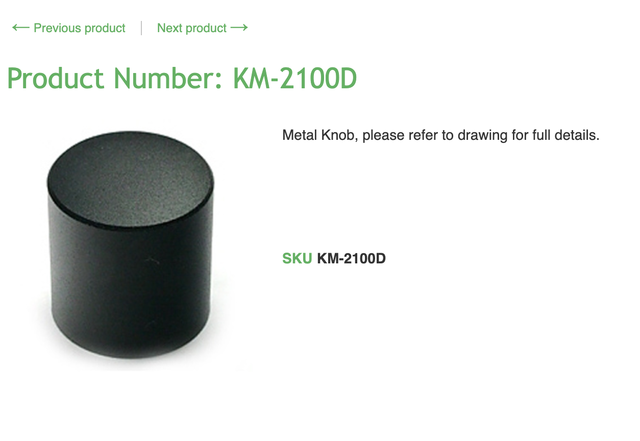
CHK is CHK Electronics Ltd, https://www.chk-electronics.com/home.php, but the knobs are sooo similar to the Cliff ones that I amost think they are the same or related. On the CHK site I found these:


This knob looks perfect, so does this, but there are no drawings to tell me the sizes. (KM-2100 is 14mm according to Ian, but KM-2500 remains a mystery)


Aliexpress

All the knobs I've found so far has been from Ali. Here is a list of what I've bought that looks good:

JU-HIVOR

https://www.aliexpress.com/item/32843175222.html


These are perfect - but unfortunately knurled shaft as always. I've bought 100 of these and they are my fallback solution if I can't find anything. 17mm in dia and 14 mm high. JU-HIVOR could not help me find anything.

DIKAVS

I was able to buy a nice knob here, but it is too low and now it's unavailable too.
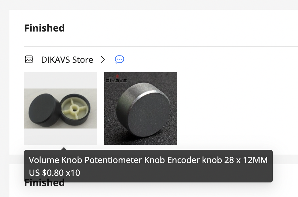

These are the best large knobs I've found - I snagged four 32mm and one 30mm ones, the last one they had. Knurled shaft of course, and nothing has appeared since. DIKAVS never got back to me when I asked for help either.


Luyu Store

https://www.aliexpress.com/item/4001093464710.html

Luyu has some reeeally good looking knobs, 10.2 x 16mm. Unfortunately, they are for switches and have 3.2mm square holes. It is possible to drill an 8mm hole and 3D print a D-shaft insert which is my fallback solution for smaller pots. Luyu did not get back to me when I tried contacting them.


Best Partner Mall

https://www.aliexpress.com/item/32952829517.html


These look great, but are too big for me and has that damn knurled shaft of course. 

Best partner mall have a lot of great knobs and I've bought a few alternatives from them too:

https://www.aliexpress.com/item/4000900076410.html

These are super nice! A bit costly but solid aluminum. If they had the same knobs in other sizes these would be my choice, even if they are quite expensive.

https://www.aliexpress.com/item/32921539254.html


Massive aluminum knobs with D-shaft. I consider using these for the main rotary encoder but it depends on what I find for the other knobs. Update: I actually bought mine from Warm Textile Home, see below


These are round shaft but that's ok for single pots. I liked that they did not look as much guitar knob.

Warm Textile Home

https://www.aliexpress.com/item/32802055908.html
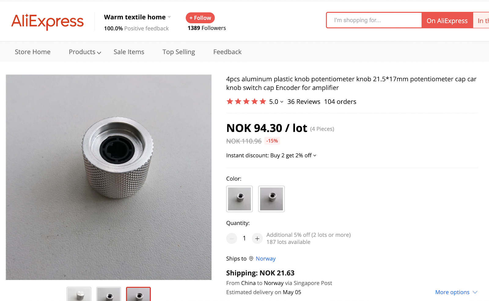

This is the same knob as from Best Partner Mail and the one I actually bought.

CW Switches Electric Store


This one is a bit of a mystery to me. I think it is the same knob as Best Partner Mail but I can't see that I've ordered from them.

Anyway, They have been super helpfull in finding alternatives. They say they can get me the one in the lower right corner with D-shaft. The MOQ is 500 and price $0.89 which is ok.
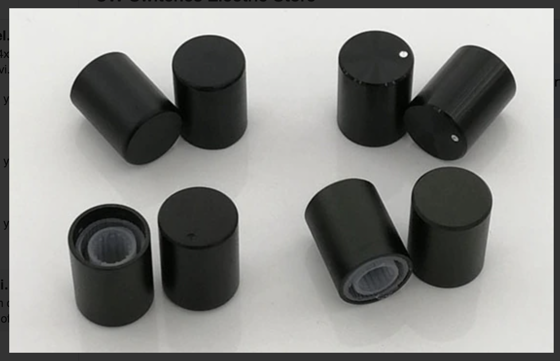

The same for 30 x 17, MOQ 500 and $1.68:


Then they suggested 15 x 17 D-axis:


This is a perfect one. I will ask for price and MOQ, and if it is within reach I will most likely buy it. 

I have also inquired about 10 x 16, 17 x 17 and 25 x 17, but that's where the dialogue stopped.

Shenzen Hengda Electronics

While not black, this is an honorable mention: A 24mm alu knob that may be a good alternative for the waveshaper/filter knobs. I have 10 of them.

https://www.aliexpress.com/item/1005003184444519.html

https://www.aliexpress.com/item/4001039507025.html

I reached out to Shenzen and they asked me for pics and details about what I need, but so far they haven't gotten back to me again.

Changshenghong

https://www.aliexpress.com/item/32873353173.html


Changshenghong has two sizes of pots that will go nicely with the ones above, though the 34mm one is a bit tall. Also, they are hideously expensive so I haven't bought any. I have not yet contacted Changshenghong ab out other variations.


HIFIw / HIFIvv / Hifi amplifier spare parts center

While not the same as the other knobs, they have some good looking knobs that MAY go well with my other guitar-ish knob:

https://www.aliexpress.com/item/32620216429.html


I've ordered a couple of these, possibly for the waveshape/filter knobs

SENGTERBELLE HIFI Audio World

https://www.aliexpress.com/item/32819963066.html

These look like smaller versions of the one above. They may be too small for me but I wanted to check them out anyway.


Other producers

Mentor

https://www.mentor.de.com/bauelemente/en/portfolio-2/portfolio-knobs/


Mentor have a few series of good looking knobs. Some are available at Elfa and other vendors, even without pointer: 

https://www.elfadistrelec.no/en/rotary-knob-without-line-aluminium-o30mm-mentor-513-61/p/11077374
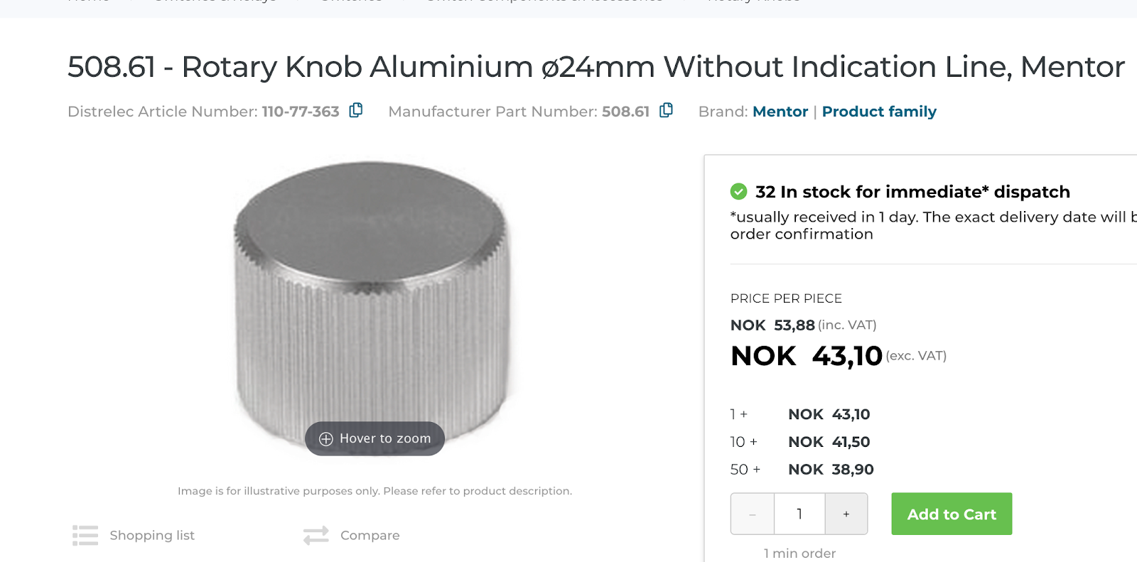
https://www.elfadistrelec.no/en/rotary-knob-aluminium-o24mm-without-indication-line-mentor-508-61/p/11077363?trackQuery=&pos=25&origPos=25&origPageSize=50


They seem to be set-screw/round shaft versions.

DuPPa

Not sure how I stumbled upon this, but I found and ordered some cool variations of the guitar knob, this one fits an encoder with transparent shaft and RGB led:


https://www.duppa.net/shop/aluminum-black-knob-with-ring/

I hoped these would look better in real life but they are, especially the gray ones, a bit scruffy. Not TOO bad though. Since the center cap is black I think I would go with the all black ones, so lets see how it compares to the other black guitar-knob-ish ones I have coming.

I did however try the gray one on a black background, and the result is pretty good, better than expected. The pics do not do it justice though


DIY

I posted a question about knobs on the Synth DIY list on facebook, and a friendly soul pointed out that I could have them CNC milled. He payed around 3 euros for the small ones, 4.5 for the middle and 5.5 for the big (in Sweden):


Final notes

Here's a quick comparison of some of the knobs
They all go fairly well with the black knobs. As long as there is some distance between the matte black ones and the guitar-ish ones they go together very well. I still lean towards the grey sandblasted one for waveshape etc as it is exactly the same as the black ones. We'll see.

I did another test on the 17x14mm black caps to see if I could get a tighter fit on a 6mm D-shaft (I have tried drilling a 6mm hole earlier and it slides on but there is no friction. This time I drilled one with a 5.7mm and one with 5.9mm drill bits. The 5.7mm does not work. The 5.9mm can be pressed on but it's too tight and I broke the cap when trying to pull it off. I think my conclusion has to be that it's not viable, which means that I either have to drill a larger hole (8mm) and add an insert, or just have a D-shaped insert, but in that case the small D-shape must create all the friction and I don't think it will work very well. All in all, If I can use the 15x17mm instead, I think that's the better option.


PS: Here is my post about custom D-shaft insert for the 10mm pot: https://atosynth.blogspot.com/2021/03/from-33mm-square-to-d-shaft.html
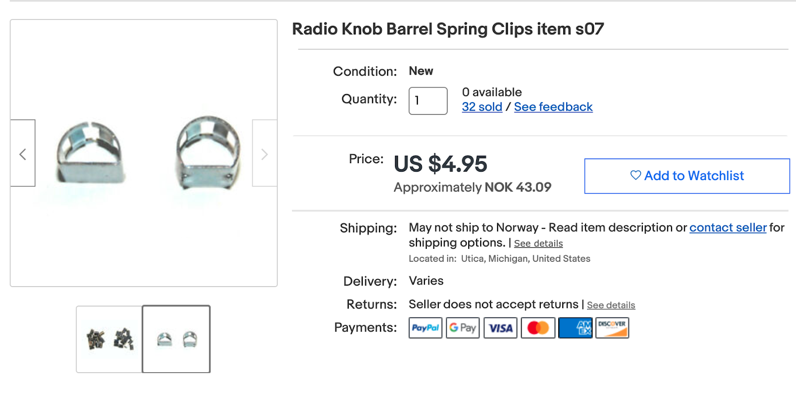
PPS: There are various inserts available but hard to find something usefull. Search for knob spring, d-shaft inserts, barrel spring, d-shaft knob adapter


https://forums.qrz.com/index.php?threads/retainer-d-shaped-and-flat-springs-for-radio-knobs.643669/
https://www.allelectronics.com/item/spr-14/metal-insert-for-1/4-half-moon-shaft/1.html

Another idea: Buy something like these and cut of the top: https://sharvielectronics.com/product/potentiometer-knob-3mm-d-shaft/


UPDATE:

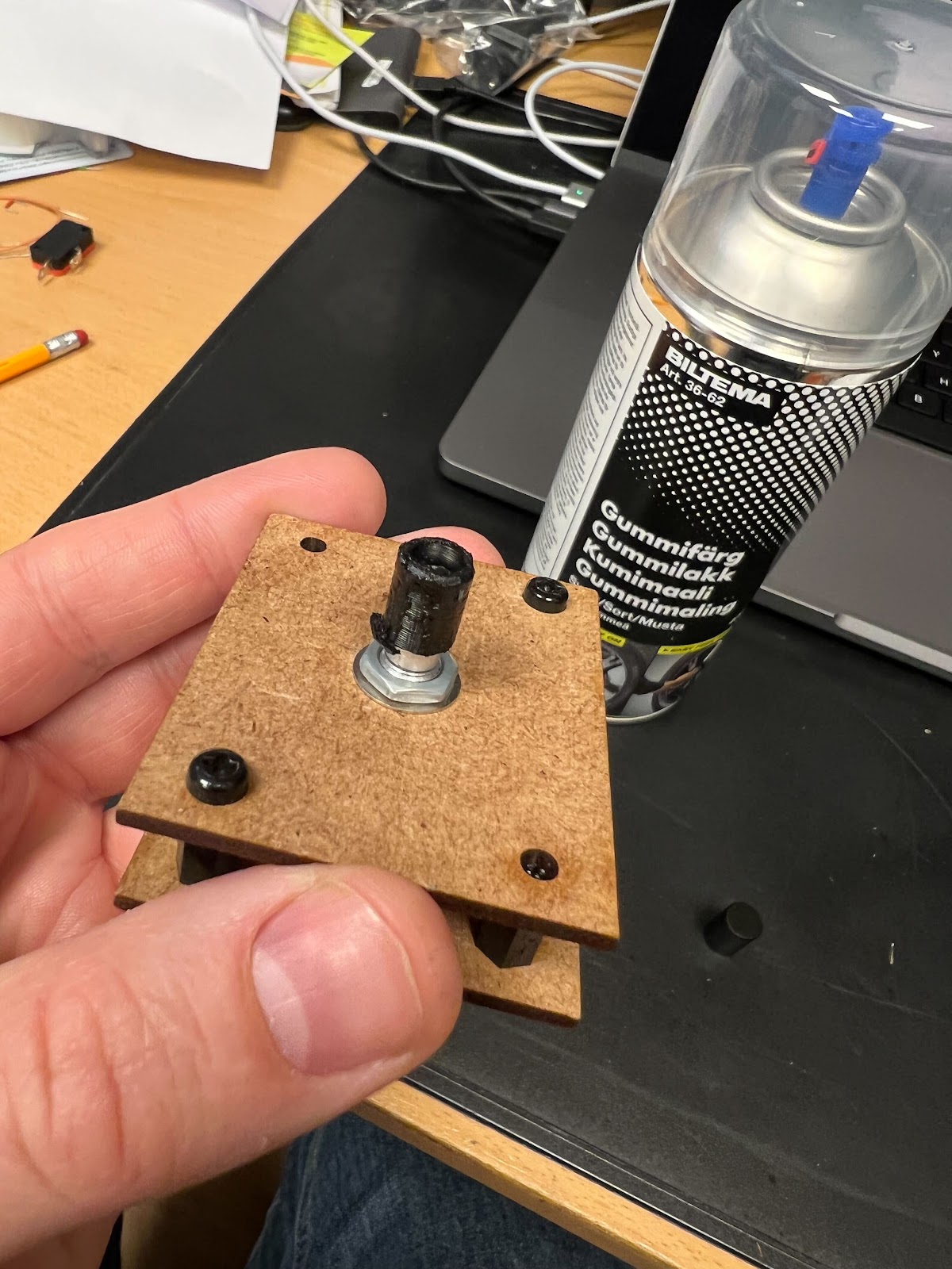
I tried spraying the 3D-printed insert with rubber spray and it works great! The knob sits firm but is still possible to remove. I will leave it on for some days and then try removing it again.


The grip was actually so good that it pulled the insert out of the cap (it had not been glued). This also showed that the rubber spray leaked through the 3D print. After letting it dry i put the cap back on and now it sits firmly again. 

I also tried spraying the outside of another cap. It adds a good grip but also removes the nice aluminum finish, and as far as I know it's not particularly durable, so I don't think I'll do it. It's nice to fall back to though, should the pots be too slippery. I did a black spray and was not very light handed so the finish was not the best, but I am sure it can be improved. I could also try transparent spray but that was sold out.

Thursday, March 31, 2022

Saving the DCOs

I've posted about this before, but I did a crucial mistake in rev 1.4 of the DCOs. Unfortunately, I also ordered a full set of them (40x) and the microcontroller and DAC (DAC8830) I used have since become unavailable at JLCPCB, so I can't just order a replacement.

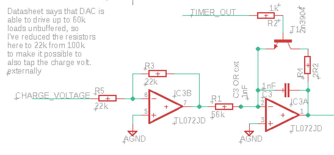
My mistake was that I reduced the resistor the DAC outputs through from 100k to 22k, thinking that it had to be less than 60k when in reality it should be MORE THAN 60k.

I need to replace R5 with a 60k resistor

Fixing this means desoldering at least one resistor, but after that I have some options.

The "correct fix"

The correct fix would be desoldering R3 and R5 and replace them with new 60k resistors. It is a bit finicky to do this, especially removing R3 will be hard. (UPDATE: Even this would not make the output perfect, see Update 3 below)

Easier fixes (?)

The DAC feeds into an inverting op amp with unity gain (Rf = Rin = 22k). 

By replacing only Rin with a 60k resistor, I would get an inverting amplifier that attenuates the signal to -Rf/Rin = -22k/60k = -0.37.

Unfortunately, attenuating inverting amps are known to self oscillate. The solution, as described here and here, is to put a resistor of the same value as Rf from the negative input to ground. 

There are a few ways to add this resistor. 

First, I may add it directly between leg 5 and 6 on IC3. It may be possible to use a 0603 resistor, or at least a 0402 directly, but it may be a bit hard.

IC3 pins 5 and 6 are in the lower right corner


Second, I may desolder R5 and put a tiny wire from the top pad to pin U1 (utility 1). Doing things that way means I could add a replacement for R5, as well as a resistor to ground, on the board the DCO plugs into. 

Charge current

Since the output from the inverting op amp now is much smaller, I also need to place a resistor in parallel with R1 to increase the capacitor charging current. I need to do this anyway, as the DAC output in my original design was 5V, but running the DCO from 3.3V means the DAC output now can never reach above 3.3V. 

Another option would be to simply amplify the DCO output. I do this right now on my prototype, I need to do some calculations and experimentation here to see what is the best solution.

Change nothing

The last option I have is to do a bit of measuring on the DAC output. When do we run into problems? Is the max 60kOhm load rule for the whole range or just for the higher values? Is it related to the output current?

If it is indeed current related, we may have a few options. First of all, maybe reducing the reference voltage, which in turn reduces the output current at max, is enough? 

Similarly, if the higher values are the issue, could I get away with using only 15 bits, leaving the MSB at 0? Testing is needed!

Update 1:

Measurements from the DCO


This is weird. I did a lot of measurements and calculations. The DAC voltages follows the pitch, no errors as we go up the scale (apart from some tiny errors at the bottom that may as well be with my probes).

However, I have connected 3.3V as Vref. According to my calculations this means the output voltages are off by 25%. BUT - when I replace Vref with 2.5V in my spreadsheet, I get exactly the output I see on the dac! The error is around 0.5%, and that's to be expected since I haven't included the slope part of the lookup. This is SO weird. I need to look at this again tomorrow.

Update 2:


Changing to a 2.5v reference made the max value drop from 2.17 to 1.66V (Expected is 2.84 and 2..16 respectively). The diff is still 23% and it is still consistent across the DAC range.

Next up: breadboard a new circuit and check if the output changes (and at what rate) when changing the resistor.

PS: the DAC output impedance is approximately 6.25 kΩ

Update 3:

I did some measuring during my lunch break, and the results are extremely uplifting:

I replaced the input resistor Rin and measured the DAC output for various values. Then my hunch told me to compare it to what would happen if we measured the mid point of a resistor divider between Vref and GND, where the top resistor is equal to the DAC output impedance (6.25k) and the bottom resistor is equal to Rin. 

The two voltage columns speak for themselves - it is clear that this is what is going on. This means that
- The output will probably be exactly the same between the various DACs I'm using
- Even if I changed to a 60k resistor, I would not get a perfect result

In other words, I can probably just leave the 22k Rin as it is, and compensate in the charging resistor part instead! This is just amazing!

Even better, I added a buffer after the DAC, to see if tapping the output for my wave player idea affects the output, and it absolutely doesn't :)

Update 4:

I tested connecting a resistor in parallel with R1 to increase the charging current. Originally I intended the max charging current to be 5V / 56kΩ = 89.3uA. Now the max DAC output is 1.94V if we use a 2.5V reference, so we need R1 to conform to 1.94V / R1 = 89.3uA, meaning R1 has to be 21725Ω. By putting a resistor in parallel with the current R1 we can lower the combined resistance - to get a combined resistance of 21.7kΩ the second resistor needs to be 35.5kΩ. If we choose a 36kΩ resistor, the combined resistance is 21.9kΩ and the current 88.6uA, fairly close to the ideal.

I tested this, and the wave amplitude instantly jumped to 9.4V (With a 3.3V reference, it passes 10V. The tops are cut off but I assume that is because the calibration output (connected to the microcontroller) is > 3.3V, I've seen this happen before).

So - all I have to do to make the DCOs work properly - with a 2.5V reference instead of 3.3V btw - is connecting a 36kΩ resistor in parallel with R1, and 75kΩ and 3.3kΩ resistors (in series, so 78.3k) in parallel with R7 to get the correct value at the MCU calibration pin - see https://atosynth.blogspot.com/2022/01/big-bug-weekend.html for calculations of R7


Increasing max frequency


Right now, the DCO has a range of 8Hz to 8kHz. I want to move this to 16Hz-16kHz (or 20Hz-20kHz).

This can be done either by decreasing C3 from 1nF to 500pF (560pF may be the closest option), or by changing the value of the resistor in parallel with R1:

We now need the max charging current to be 178.6uA, meaning R1 should be 10.86kΩ. The necessary parallel resistor would be 13.4kΩ. It is better to choose a slightly lower value than a too high one, so 12k may be the best standard value.

Update 5:

By swapping R1 with a combined resistance of 14.5kΩ and using a Vref of 2.5V I'm able to cover the full midi range (8Hz to 13.3kHz) with only 3 cent errors on the highest pitches. This does not leave room for pitch bend at top/bottom, but each note is exactly 512 steps up from the previous which is a nice number to work with in the voice controller.

Reducing to 9.1kΩ lets us add another 12 semitones, giving us a range of 5Hz to 21kHz, though I'm not sure it's worth it.

All in all, I think I should consider making a bootloader for the DCOs, there are so many things that could be changed after install, and having to manually change 16 (or 32!) of them would be a real pain.

Wednesday, February 16, 2022

Envelope time curve - midi mapping

After looking at the transfer function of the Little Phatty, I decided to redo the mapping for my XM8. In the same way as with the level function, I'd like to make it dynamically changeable, to be able to dial in the perfect transfer function per envelope.

The LP has an envelope time (per the manual) of 1ms to 10s (10.000ms).

The midi transfer function, with f(x) in ms, is thus

f(x) = 10^(x/(127/4)), for x=0 to 127


To get a changeable function, I looked at my previous work on envelope curves. I have a general function with built in steepness.

A function starting at 0,0 and ending at 1,1 with variable steepness can be written as

f(x) = a * 10^(steepness * x) - a

where

a = 1/((10^steepness) - 1)

Extending this to a case where we want a highest value for input and output, we get

f(x) = Y_max * ( a * 10^(steepness * (x/X_max)) - a)

where again

a = 1/((10^steepness) - 1)

Unlike the LP function, this starts at 0, since I use a 0-indexed time where 0 is the shortest possible time, around 1ms. If we want a different starting point, we get

f(x) = Y_min + (Y_max - Y_min) * (a * 10^(steepness * (x/X_max)) - a)


Sunday, February 13, 2022

Little Phatty envelopes

Envelope sustain level

I've been trying to make curves to map a linear pot to envelope sustain level. I've added a function that generates a dB-accurate mapping, with adjustable dB range, but I'm having a hard time dialing in a curve I find pleasing so I thought I'd have a look at what the Little Phatty does.

I took 128 measurements of the vol env output on my Little Phatty, one for each midi step. This is the result...


In other words, perfectly linear. I noticed that each step varies somewhat, so it is safe to assume that the internal resolution is much higher than 128.

Also, the pot is linear, midi 63 is straight up etc, so generated CV is 1:1 with the pot position.

The envelope CV feeds an LM13700 based VCA. It is in itself linear, but the control signal circuit may still change the envelope. I will have to simulate this to be certain, but since the envelope is in fact exponential in itself it is a good guess that control is still linear? But if so, the sustain level setting will not be very nice. I'll try that as well.


Update: Here is a plot of midi sustain value vs amplitude of a square wave:


It confuses me. In the beginning the output level increases rapidly, but then as we get higher the rate of change drops. But doesn't perceived loudness work the other way around?

Here is the plot overlaid on a recording of me turning the sustain pot fairly evenly:


It matches well so the curve is absolutely right. And it sounds ok too. In a way, it feels exactly like it looks, starting from the top things change fairly linearly until the pot is halfway (though it doesn't feel like it is HALF the volume. Then it drops much more rapidly.

I tried some new variations on my own synth. a 23dB curve, which (going down) ends at 2319, or 7% of max volume, sounds very linear to me. It is not fully off, so we may need to cap it at the lower end, which is exactly what the Little Phatty curve does - that one seems almost linear 3/4 of the way down. I tried doing something similar but it just doesn't sound good to me. I think I'll stick with the 23dB.

Closer look at envelope shape and times

While I had the LP hooked up I had a look at the envelope outputs. 


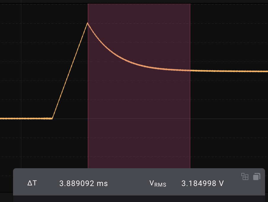
Shortest attack is 1.3ms, and the attack is linear

Decay to center is 3.9ms

Decay to bottom is approximately the same


Decay to 75% too


Release is in the same range, looks like approximately 5ms.


At 15, attack is 3.83ms

At 31, attack is around 12ms, or 10 times the fastest

At 47, attack is 38.3ms

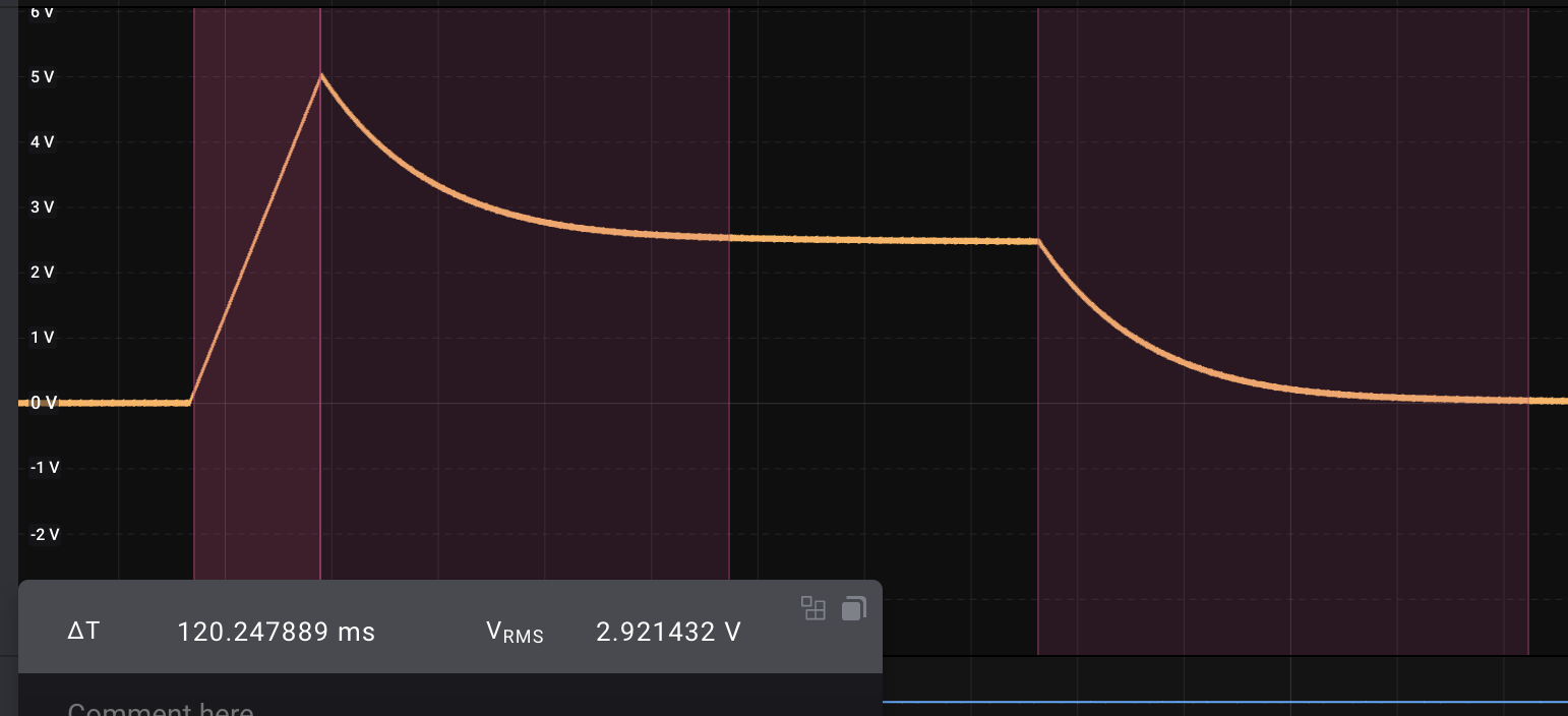
At 63, the envelope looks like this:


Attack is 120ms, decay around 385ms and release around 460ms, pretty much exactly 100 times the fastest.


At 95, Attack is 1.2s and the others are similarly 100 times the shortest. Something interesting to note too is that the envelope keeps dropping even after the initial decay...

In other words, we have exponential growth from 1ms to 10s, quite expected really :)

(The actual transfer function is f(x) = A*10^(x/32), where f(x) is the level, A is the time at X=0 (1.2ms if we cheat a little) and x is the midi value).

The manual says the ranges for all stages are 1 to 10s. It seems that this is not quite correct for decay and release, but attack is definitely close.


One final thing - sample & hold

Oh, and a little thing I noticed while studying the Slim Phatty schematics - Sample and hold buffers use 1nF caps and LF353, multiplexed through DG408s. The signal looks more noisy than what I get, but that is though a long signal cable. The dac is DAC8581, which has a settling time of 0.65uS for a 10V change.

Monday, January 31, 2022

Matrix recalc speeds

Sooo... Since I realised that the matrix recalculation takes too long, I did some quick calculations and a tiny fix.

By changing the matrix accumulator from an int64_t to an int32_t, I got a reduction from 81us/loop to 48us. Looks like this fixed the envelope "jitter".

Then I started looking at how much happens during recalculation.

We do a staggering 2719 iterations over various params. If we assume that we can achieve 600 instructions every us (600MHz), and we do 12000 loops every second, we have 600 000 000 / 12 000 = 50 000 instructions available to us per loop. Divide this by 2719 iterations.and we end up with 18 instructions per param calculation. That is WITHOUT taking into account everything else that happens during that time, like calculating envelopes, updating the S&H buffers and writing to the DAC.

This is surprisingly low. I am not sure I can make it work but it makes for a great challenge! I should really start looking into more efficient matrix multiplication. 

Update:

Removing amount != 0 checks, e.g. calculating ALL possible params all the time, makes the loop time jump from 48us to 105us.

But then, replacing / 32767 with >> 15 (/32768) brings the time down to 71us. We do get a tiny accumulated error here, I need to check the implications. But it means the worst case scenario is 71us/loop if everything is modulated all the time (?). Still too much, but not as bad as expected. Combining >> 15 with still having the amount check will be the best solution for now.

Not updating envelopes after calculations dropped from 48us to 31us, so we should definitely check for changes before updating.

Things to try: Swapping ints for 32 bit floats and using range [-1, 1]. Means we don't have to divide/shift every calc.

Inline array lookups instead of using variables (though the compiler should figure this out...)

Update 2:

Adding a check for each destination to see if it is necessary to calculate the matrix brought the time down from 48s to 11us (but this will get progressively worse when more things are dynamically modulated). 

Should also add a check to see if env/lfo params have changed before actually updating, as this is a costly process.

Sunday, January 30, 2022

Big Bug Weekend

This is another one of those not-too-exciting posts, but one that sums up a lot of stuff I've done over the weekend.

Filter

I started off with work on the filter. As mentioned in the previous post, it now tracks the keyboard. I also added a filter envelope, but envelope amount is still missing.

I then did some quick calculations on the consequences of using +/-12V instead of +/-15V.

First of all, the filter cutoff mixer has a 270k resistor to V-. It raises the initial cutoff frequency by 5.55 oct with -15v, and 4.44 oct with -12V. Similarly, we have a trimmer between +/-V which lets us trim the same range. We do lose some range when reducing from 15 to 12V, but I have not yet tried trimming the filter so I'm unsure if it's an issue.

Second, the reference current in the cutoff exponential converter uses a 1M5 res to -15V to generate a 0.01mV current. This will now be 0.008mV, and it linearly offsets the cutoff frequency. This can be trimmed away using the cutoff and tracking trimmer, but again I have not tried to do this.

Third, the dead bands for resonance and VCA, e.g. the minimum voltage needed to start changing the params, will change slightly - from 12mV to 12mV for resonance, and 10mV to 8mV for the VCA.

All in all, the filter will probably work well though it needs a bit more testing.

DCO

I decided to get the second DCO going yesterday. I had to find and set up my windows computer, but other than that programming it went without issues. I decided not to try to figure out more about why it outputs 5V instead of 10V at the moment, as I was simply too tired to look at the code. UPDATE: It is because the 3.3Vref combined with using a 22k load on the DAC actually turns it into a 0-2.5V range instead of 0-5, so the charging current is half of what it should be)

DCO calibration

I did however look into how to fix the calibration circuit. The DCO uses its Vcc as a reference when trying to calibrate wave amplitude, and also for detecting "overflows" when pitch changes.

The PIC16F18346 has an internal 6bit DAC which in my case uses Vcc as reference. This has been set to 26/32 * Vcc for calibration and 27/32 * Vcc for overflow detection. 

When Vcc changes from 5V to 3.3V, calibration threshold goes from 4.0625V to 2,68125.

The onboard calibration circuit is simply a resistor divider with a 100k and 68k resistor. It divides a 10V input down to 4.048V, so by using the 4.0625V threshold we should be able to get a 0-10V output from the DCO.

When using Vcc = 3.3V instead, we need to make divider divide 10V down to approx 2.68125. As both ends of the 68k resistor are exposed, we can but another resistor in parallel. Using a combination of a 75k and 3.3k resistor (in series, so 78.3k), we end up with 2.668V from a 10V input, which is close to the same "error" as the 5V version.

As for overflow detection, 27/32 * 3.3 = 2.78, which means the output will reach 10.4V before overflowing. That's about 4% higher than the correct value. I'm not sure if this is audible, we just have to test it.

DCO DAC ref voltage

This cannot be higher than 3.3V when running with Vcc = 3.3V. I have yet to calculate what this means for maximum charge current etc. 

DCO 2 on voice card controller

Now, this opened up a giant can of worms unfortunately. Once DCO 2 was in place, the top of the saw wave from both oscillators got cut off at around 4V. As the only thing connecting the two DCOs are the sync lines, I immediately suspected that something was going on there.

I completed the code for turning on and off sync, but that didn't help, so I decided to move DCO2 from its socket to a breadboard and run breadboard wires to the socket, to better be able to connect/disconnect the sync lines.

Unfortunately, while doing this, I swapped the DGND and +5V pins on DCO2. Fearing I broke something, I disconnected DCO2 and started testing the rest of the circuit. 

Now I noticed a sort of metallic sound on the attack portion of each note. This led me through a wild chase to pin down the problem. I swapped the DCOs, fortunately DCO2 still worked. I figured that the sound originated AFTER the filter and then realised it came from the envelope VCA CV. I tried replacing the CV DAC and sample & hold boards as well, with no result.

I then turned to the code and did a git diff. I quickly realised that I unintentionally updated DCO2 twice, once to the real CV and then to 0 to disable changes while debugging sync. This should really not have anything to do with the CV generation, but after a lot more debugging, it turns out that it somehow messes with the timings. It looks like every second update of the CV failed, and from the look of it one or more of the bits sent to the DAC was missing, or at least that is my theory. Removing the extra update fixed the metallic noise.

Envelope CV (bottom). The signal drops to an almost fixed level for every second update. The level follows the curve of the envelope, which leads me to believe that it's a case of missing bits in the DAC value.

I am quite certain that this issue will come back and bite me later!

DCO sync

Now, after all this, I finally went back to debug sync. I did realise that what was probably going on was something I've seen before - trying to input a voltage higher than Vcc to a pin on the MCU makes weird stuff happen. That was why I wanted to move DCO2 to the breadboard in the first place. I realised I've connected DCO out to the sync pin of the other DCO, meaning that it would see up to 10V! After carefully connecting DCO2 again, I could confirm that this was in fact the issue - though not exactly how I expected it to be.

What happens is that the OUTPUT of the DCO gets cut of at around 4V when connected to the sync pin. When I instead connected sync to the timer output of the other DCO, sync started working perfectly. I remember now that this was how I intended it to be done between two DCOs, I only opened up the posibility to also use an analog wave as input, but forgot that it has to be limited to 0-3.3v.

Hard sync. The waves are in phase in reality, I've only tapped them at different points in the circuit.


Missing +/-12V on the DCO debug headers 

This is just a tiny thing, but it threw me off for a bit. I have forgotten (?) to connect the analog power pins of the DCO to the debug pins next to the socket, so I didn't get any power to the DCO on the breadboard. This is fixed in v1.2.1 of the controller board.

Unexpected refresh rate and S&H caps

I can't remember what rate I was aiming for, but right now the S&H runs at 196kHz. That means around 12kHz per channel. I only wonder because I have a commented out line above it with twice that rate.

When replacing the S&H board, I realised that the one I have in the circuit uses 2.2nF caps. Not sure if I used the same board for testing in my earlier post, but it explains why I've seen a few examples where we couldn't charge the cap fast enough. However, it also tells me that 2.2nF is probably fine :)

Envelope nonlinearity and missing updates

This surprised me. When debugging the metallic noise, I realised that the envelope CV is not perfect, it has small drops along the way where it reverts to the previous sample instead of the next.

Turns out this is because the calculation of next step takes too much time, though not EVERY time for some reason, so the double buffered output array has not been updated and the old value is sent instead.

The output drops to the previous value for one cycle, then goes up again.

I added a counter that is incremented when this happens, and it looks like it actually happens A LOT. Matrix recalculations simply take too long, even with the very small number of params I'm using. This is extremely disappointing and something I need to look into

Here is a way of getting an average without constantly summing several numbers. I can use this to get average cycle time. If it overflows I can use two levels, first averaging 1000 and then averaging those again.


Update: It seems one update cycle takes about 80us. As it is run 12000 times per seconds, the updating alone takes 960000us, or 0.96s per second. This does of course include the time it takes to update the output, as that is interrupt based and happens during the calculations, but we need to look at what is actually taking so long. 80us should give us at least 600 * 80 = 48000 instructions to "play" with.

Testing using Little Phatty

I also had time to do a bit of testing and measuring with the Little Phatty.

Pitch bend

First of all, using the pitch bend on the LP made the stepping sounds go away, just as expected. The MPK25 simply does not have high enough resolution.

Clicks when filter keyboard tracking is off

I also confirmed that the LP makes some similar clicking sounds as the XM8 when filter keyboard tracking is turned off. Not entirely unexpected.

Pitch range

The LP pitch range is approximately 26Hz to 31000Hz when only using the keyboard - Osc set to 16' and lowest key + mod wheel all the way down = 26Hz, 2' Osc, highest key and mod wheel up = 31kHz (I'can't hear the last 5 semitones, and the last ones are pure sines on the scope).

The MPK25 sends midi note 0 to 120. Using midi from the MPK25 I was able to get down to approx 8.3Hz. As for the top, I can't get past oct#4 G# for some reason, and the pitch bend started working in the opposite direction??

I had some issues where bend up did not work for note 120, for 119 it works a bit so not entirely sure what is going on. I can't see from my notes if this was in fact for the LP or for XM8 though!

Electric Druid VCDO range

I started looking for what other DCOs do. The Electric Druid VCDO does 8-8kHz.

Juno range

The Juno apparently covers the entire midi spec range, by having a clock divider on the master clock for the two lowest octaves. It stays within 6 cents of the perfect pitch for all notes except midi note 127. More on this at Electric Druid.

Thursday, January 27, 2022

Filter cutoff - keyboard tracking

I did some work on the filter today. First, I switched from a 100k to a 36k resistor between the CV input and the 0-5V CV. This changes the filter range from 5 octaves to 14 octaves, like the original juno filter. 

I then added pitch to the filter cutoff cv in the matrix, making sure to compensate for the fact that the pitch range is 10 octaves and the filter is 14 octaves. Instant success! The filter tracked almost perfectly from the start, now the output amplitude stays constant between notes and most of the annoying clicks when changing note is gone!

I also added pitch bend. At the moment it has a lot of stepping when running from my MPK25, I will retry with pitch from the Little Phatty, I think this is only a midi issue. There is some noise on the pitch bend too. I first suspected that it was digital noise from the SPI bus, but when I did a small program change that updated the DCOs without actually changing the pitch, the clicks went away. Thus, they are entirely related to either DCO artifacts or the missing filter tracking.

Sunday, January 23, 2022

Emulator II PSU not working.

Crap. Testing the EII regulator board now, and something is seriously wrong. The power led keeps going on and off. 

I disconnected the +/-15V outputs and the 5V works fine. Reconnecting the +15V also works - but I can't trim the 13.2V all the way up, it stops at about 12.95V. That really sucks.

But the worst is that when I add -15V the flashing starts again. Damn.

Update: The -15V is caused by me messing up the polarity of the caps. Such a beginner mistake... The 13.2V is due to the PSU, even under load, only outputting +14V. I have an identical one that outputs 14.5V, that works as it should. Not sure if that means the first one is outside spec or what is going on...

Thursday, January 20, 2022

Voice card build and testing

I should really start off by screaming as loud as I can: "It's aliiiiiive!". This monday I hooked up a DCO, the waveshaper, a waveshape mixer, the Juno filter and an output VCA, all controlled by the voice controller and its internal modulation matrix. For the first time, I'm able to play my synthesizer using an external midi controller. It feels amazing! To think it took 7 years to get this far...

Anyway, it is not without bugs, but that's why I'm doing it this way in the first place, to test everything and how it works together.

There are a lot of things that work great right from the start. The waveshaper does its job perfectly, giving triangle, bi-directional saw, pulse with PWM and two sub oscillators with selectable square/saw output. 

The waveshape mixer CV generator I designed earlier works perfectly, as does the pulse wave amplitude control. 

The filter filters, though the range may be a bit lacking. It resonates beautifully too. I have yet to calibrate it and test it fully after moving from +/-15v to +/-12V. 

Finally, the output amp and envelope works great, though I had to fix a few rather hard to find bugs in my code.

Now, for each module, here are some things that must be fixed or improved.

Waveshaper

The sine wave amplitude is +/-4V while all the others are 5V. This can be fixed in the voice mixer by changing the input resistor or I can fix it on a new revision of the waveshaper.

The saw and triangle waves have noticeable ringing (noticeable on the scope, not necessarily audible). Adding caps in the feedback of the output will remove most of this. The rest goes away in the filter but I am not sure if it affects anything else. 

Pulse width: I don't think the pulse width is quite narrow enough.

When calibrating the symmetry of the sine wave, I can't seem to get a perfect setting that also gives a centered triangle wave. It is not a big issue though, but it means that the triangle is slightly "lower" than the other waveforms, perhaps by 0.5V or so. It is not audible, but it may affect how the circuit clips when mixing multiple oscillators. I'm going to leave it as it is for the time being.

The square wave sub oscillators are not centred. This is because the reference voltage used in centring is derived from -15V, and when changing this to -12V the reference is wrong. Again not audible but nice to fix.

The triangle and sine waves have a very visible notch at the end of the phase, more about that in the DCO paragraph.

Waveshape mixer

As I wrote in my last post, the AS3364 has a sort of dead band in both ends of the CV. Since all waveshape mixer CVs are generated from one input, it means that there is no way to compensate for this without changing the CV generator. In practice, the dead band means that one waveform fades out completely before the next one has reached its maximum. This is especially apparent in the saw to pulse cross fade, where the wave has become a square before the square has reached its top. It is not particularly pronounced so I don't think I'll do anything about it.

DCO

These are not properly wired up yet, so some of these things may go away - right now they run with the wrong calibration circuit and only produce a 0-5V wave when they should give us 0-10V (at least that's what the waveshaper expects). To compensate for this, I'm running the wave through a non-inverting op amp amplifier with 2x gain.

There are a few shortcomings/bugs in the DCO. First of all, some ringing is introduced along the way. I've added a cap to the feedback of the non inverting amp, a 15pF in parallel with the 56k resistor I'm currently using.

It looks like discharging the DCO cap goes too slowly. Either that, or we are limited by the slew rate of the op amps. In any case, this means that the drop from top to bottom of the saw wave is not instantaneous. When generating the triangle wave we invert half of the saw wave to get the "missing" portion of the triangle - but since the falling edge is not perfectly vertical, we get a notch at the end of the triangle phase. I can't say I hear it, but  at 8kHz it is very visible on the scope.
DCO discharge is not vertical enough, leaving a notch in the saw wave.

Adding a 5p cap across the DCO output op amp takes away much of the ringing at the start of each cycle


15p cap takes away even more of the ringing. Saw output from the waveshaper at the bottom, some new ringing has been reintroduced.

Clicking on envelope retriggers: When we play a new note without releasing the previous one, we get a bit of clicking. So far I've been able to identify two probable causes - output amplitude and centring after the filter, and glitches in the DCO.

The DCO glitches manifest themselves as discontinuities in the triangle wave, it suddenly and abruptly changes value. The reasons are:
  • When changing from a high to a lower pitch: It looks like the period timer is not reset. Instead, the period is reset when the original frequency would have been reset. This means the amplitude is too low and the start/end matching of the triangle fails.
Saw does not reach its maximum as it is reset at the "old" frequency
  • When changing from a low to a higher pitch: now the timer lasts too long, meaning the cap is charged more than it should. It reaches its max and flats out, both distorting the saw/tri and introducing a spike with too high amplitude. That would definitely sound like a click. 


The last of these is to be expected. The DCO is supposed to check the amplitude against a known voltage, but without calibration this won't work. The other one on the other hand, is stranger. I need to check the code.

I also got a more serious error while testing the very limits of the DCO. When playing OCT+4 on the MPK-25, switching between e and g makes the DCO drop to a much lower frequency for a single cycle before recovering. It happens consistently. No idea what makes it happen.


Finally, the range of the DCO is currently too narrow. It maxes out at around 8.5kHz but should reach at least the double or ideally above 20kHz. Replacing the integrator cap and regenerating the timer code will probably solve this.

Filter

As with the DCO, the filter cutoff range needs looking into. I have not tried calibrating the filter at all, so it may not be a real problem though, but it looks like the filter is not open enough with CV at 5v.

There is also something going on when changing the wave frequency. Obviously, when the wave frequency reaches the cutoff point, higher frequencies will be attenuated more, so with the filter at a fixed cutoff, switching between two notes will make the amplitude jump up and down. This may be part of the click-sound I'm hearing. Also, the filter has some form of DC filtering, so the balance/centring of the wave changes with waveform/content. This is particularly visible with narrow pulse waves and resonance. Again, a bit of calibration may improve this but I also need to see what other synths do. Also, introducing keyboard tracking means that relative amplitude should not change as much between the notes.

Some kind of noise at the start of the envelope (not visible in the CV). This was before I hooked up a probe to the filter output so I don't know where it originated from


Weird glitch in output, again, no idea what this was, especially since it is not at the start of the envelope.

Quick retriggering that changes frequency leads to amplitude changes after filter

Output from filter is not centred. Had a lot of resonance and wave was not symmetric around the X axis.


Envelopes

These are software, and mostly finished. I still need to hook them up to the GUI to make it easier to test them, but for now they are controlled through 7bit midi. As they have a very large range - 1ms to 30s, I have to use some kind of linear-to-exponential mapping, or we would not get any resolution at the lower parts of the range. 

I feel that the mapping I use now still does not have right response to it. Fortunately, I have a script to generate mappings with so it's only a question of tweaking this.

GUI

The GUI should - in theory - output everything needed to control the synth over midi already. But since I want to PLAY the synth using my Akai controller, I'm using up the only available midi port on the voice controller card. I need to find a way to merge the midi output from the GUI with the controller. I THINK that MidiPipe may do the trick.

AS3364 response confirmed

I did a new test of the CV response for the AS3364. Connecting a 5V to the input, and a 0-2V (actually 5V but through a 33k/22k resistor divider at the CV input) saw wave connected to the CV gave the following output:


As we see, it has a confirmed "deadband" at the bottom, it doesn't start to get linear until about 250mV CV. Similarly, linearity breaks down again at the top, around 1.8V. Mind you, this is NOT distortion of the input SIGNAL, it's only the control that flats out, so it doesn't have too much of a consequence. If it becomes a problem it may be trimmed out in the CV generation.

This is for one chip only, I have not yet tested multiple to see if they respond differently. Nor have I done any temperature testing - after all, we're still dealing with an expo converter inside the chip, though I'm not sure if that is a problem.

Monday, January 10, 2022

Voice Controller v1.2b testing, including 16ch sample & hold

I've finally started testing the voice controller card that I made last spring. It's been so long it's almost a bit scary to start testing.

Voice card controller with peripherials

In the image above: To the left is the PSU interface. At the moment I get +/-12V from a Doepfer PSU. A 5V input is available but not used as the Teensy gets 5V from USB and powers the rest of the circuit through its internal 3.3V regulator. To change this later requires a trace on the Teensy to be cut.

The teensy (4.1) is the long narrow board closest to the top. Below it is my custom DCO, and left and right of that is DCO memory and reconstruction filter respectively. 

The tiny chip on a tiny PCB to the right of the midi sockets is a DAC, the card has room for four of them to be run in parallel.

Each DAC controls a 16ch multiplexed sample & hold card - those are shown to the right. In theory this should give me 64 CVs to play around with when the card is fully populated.

At the bottom is two port expander cards, each with 16 i/o pins for a total of 32 digital pins that can control switches etc on the voice card.

Testing

So far I've tested: 

Midi in and out - both work flawlessly. I use an H11L1 optocoupler running at 3.3v, both resistors in the input circuit are 220Ohm.

The two DCO positions, they both work fine but I only had one working DCO so I couldn't test sync between them. DCOs are controlled through SPI1 (hardware SPI).

DCO with constantly changing frequency, showing how it does NOT reset on frequency changes. Mmmmm.... Calibration is not in place yet so it does not reach full amplitude.


Port expander. I had to write my own little lib for these but it works great. Shares SPI1 with the DCOs.

DAC in slot 1. It's controlled via bit banged SPI at 50MHz and works great :) 


Now, yesterday I did a bit of soldering for the first time in years. I've built an enclosure that I hoped could help me with my health issues, but I'm not satisfied, I still felt considerable discomfort afterwards. Not completely sure of why though, but that's for another post.

Anyway, that meant that today I'm able to test the sample & hold circuits. First tests are very promising. Running the DAC at half the reference voltage (3.3v from the Teensy at the moment) shows 3.279-3.284 on my Saleae Logic Pro 16 scope pins , and alternating between 0 and 3.3v on each s&h pin shows hardly any visible artifacts at the start of each charge cycle. I'm using a 470R resistor between the dac buffer and the s&h mux btw, and this is the S&H board with 1nF caps (I have some with 2.2nF too, I will experiment with both combinations later).

I see a tiiiny dip at the start of the cycle, it consistently drops to 3.274V. The Logic Pro resolution is 5mV, so exactly how much a constant value fluctuates and how much it drops on charging is unknown, but around 5 to 10mV at most seems to be a good estimate. On the breadboard this drop was 30 to 50mV, so we're almost at an order of magnitude improvement, that's a good thing. A quick test with a board with 2.2nF caps instead of 1nF made the dip go away completely - but such a board may not be able to achieve the refresh rate / charge speed we need.


The dip when charging, dropping from 3.284/3.279 to 3.274 on the scope

The hold time is approx 80uS and there is no visible droop during that time. It also means that our refresh rate is around 12.5kHz.

A 5mV drop means we're seeing a 0.1% error at that moment. However, it only lasts for 0.3uS (out of the 80uS per cycle). I think it would be very hard to notice even for pitch CV though it may introduce a slight vibrato, who knows.


Thursday, December 9, 2021

Roland M-240 PSU

I have an old Roland mixer, the M240. I've had it for years, ever since some idiot screwed me over when i bought it, promising to send me the power supply but never doing so. I did a little research of the internals here: http://atosynth.blogspot.com/2013/07/roland-m-240-power-supply.html

Today I finally googled a bit about it again, and found two interesting posts made about a year after mine:


https://djjondent.blogspot.com/2014/10/roland-m-240-mixer-power-supply.html

https://djjondent.blogspot.com/2014/11/roland-mixer-power-supply-replacement.html


Basically it says that the PSU is a simple centre tapped transformer with a diode rectifier and two caps. From Jon's posts it is clear that at least the Boss PSU he uses has two large filter caps in it - it's hard to read the ratings - 35V is clear but is it 220uF or 2200uF? In any case there are two 2200uF caps in the M240 so anything (or nothing?) would be fine I guess.


Jon uses the Boss ACE-120 but that is not the original PSU for the mixer and it is 300mA, not 500mA. I couldn't find an ACE-240 anywere either, so I had a look in the owner's manual for the M240. It says the following:


Aha, so for my 240V mixer I need the ACC-240A or E, not sure what the difference is - and it is rated at 32VA

It would be quite easy to build a power supply, but I will still have to find a matching plug and THAT won't be easy. 

Friday, August 20, 2021

Analogish bit crusher

 I just came across this great post about an analogish bit crusher and sample rate reducer from Juanito Moore and Kristian BlÃ¥sol in the Synth-DIY group on facebook:


When I made my mcu-based bit crusher I was thinking about doing something similar but couldn't think of how to do the actual bit crushing - this solves that :)

But that got me thinking - could we do away with the ADC too?

Turns out we can of course. By making a flash ADC using comparators for example:


Instead of the 8-to-3 line encoder we could put D flip-flops and clock them, to reduce sample rate. Maybe we could even find a way to re-use the flip-flop as a switch, to combine it with the bit crush-comparator outputs? D flip flops with preset and clear seem able to do this as long as preset/clear are level controlled, not edge.

We can also use the 40174 hex D-storage, which stores 6 bits of info (but does not have a preset though)

If we want to go all-analog we could instead use sample and hold buffers for the bits, though we may not be able to have a combination of both very high and low sample rates as the leakage during hold vs charge time during sample may be incompatible. This could be improved by using a second set of comparators on the output of the S&H so that a voltage drop won't be visible on the DAC side of things, but now things start getting a bit complicated :-D


All in all not a terribly practical project, but fun none the less.

Thursday, July 15, 2021

Opening a waveshare 2k screen

I bought this 9" 2k screen recently:

https://www.waveshare.com/product/raspberry-pi/displays/lcd-oled/9inch-2560x1600-monitor.htm 

https://www.waveshare.com/wiki/9inch_2560x1600_Monitor


As I intend to use it for my synth, I want to extract the screen from the box - or at very least find a way to safely mount it and attach the cables inside the synth.

I contacted waveshare support, and while they said that they could not do this for me (not a problem) for such a low volume, they did send me some great pics of how to open the rear, which also means that I can possibly access and move the connector boards. I may not be able to fully remove the screen though, so I need to create some kind of bezel for it.

Oh, and I almost forgot - accessing the insides means I can connect wires to the on/off button to control it digitally.


Here is a cool ribbon cable based hdmi: https://www.aliexpress.com/item/1005002200767476.html?spm=a2g0o.productlist.0.0.726a3ff1r9Ggaf&aem_p4p_detail=2021071512223512888029912608890037608317

Wednesday, July 14, 2021

Super saw analysis ideas

I found a post on Matrixsynth today that lead me to a second paper analysing the JP8000 super saw. 

The post: https://www.matrixsynth.com/2021/07/korg-nts-1-nutekt-digital-synthesizer.html

The project: https://github.com/GrahamJamesKeane/UberSaw

The project page: https://korgnts1beginnersguide.wordpress.com/

Adam Szabo: How to Emulate the Super Saw: https://korgnts1beginnersguide.files.wordpress.com/2021/07/szabo_adam_10131.pdf

Alex Shore - An Analysis of Roland’s Super Saw Oscillator and its Relation to Pads within Trance Music: https://korgnts1beginnersguide.files.wordpress.com/2021/07/ananalysisofrolandssupersawoscillatoranditsrelationtopadswithintrancemusic-researchproject-a.shore_.pdf


This got me thinking - I still think the detune response looks like it consists of three linear components instead of a 11th order polynom like Adam Szabo shows in his paper (I did in 2014 as well when making my analog 7-saw module).

I really want to test my theory in detail, but that requires some automation. Here's my idea:

- Control the JP through webMidi

- Loop through all midi values for detune

- Use a js spectrum analyzer, for example https://github.com/hvianna/audioMotion-analyzer to find the frequency components. We should be able to find 7 distinct maximums (the 7 oscillators). 

- For each maximum, record the pitch and amplitude, possibly as an average over several samples

- Build tables for each oscillator/detune setting and calculate spread and pot response to see what the actual response is.


Edit: I've been looking at the Web Audio API lately, and using it directly could be a good option. It works by chaining nodes, one of them being a FFT node. I assume that can be used for finding the maximums.