Showing posts with label Exponential. Show all posts

Sunday, February 13, 2022

Little Phatty envelopes

Envelope sustain level

I've been trying to make curves to map a linear pot to envelope sustain level. I've added a function that generates a dB-accurate mapping, with adjustable dB range, but I'm having a hard time dialing in a curve I find pleasing so I thought I'd have a look at what the Little Phatty does.

I took 128 measurements of the vol env output on my Little Phatty, one for each midi step. This is the result...


In other words, perfectly linear. I noticed that each step varies somewhat, so it is safe to assume that the internal resolution is much higher than 128.

Also, the pot is linear, midi 63 is straight up etc, so generated CV is 1:1 with the pot position.

The envelope CV feeds an LM13700 based VCA. It is in itself linear, but the control signal circuit may still change the envelope. I will have to simulate this to be certain, but since the envelope is in fact exponential in itself it is a good guess that control is still linear? But if so, the sustain level setting will not be very nice. I'll try that as well.


Update: Here is a plot of midi sustain value vs amplitude of a square wave:


It confuses me. In the beginning the output level increases rapidly, but then as we get higher the rate of change drops. But doesn't perceived loudness work the other way around?

Here is the plot overlaid on a recording of me turning the sustain pot fairly evenly:


It matches well so the curve is absolutely right. And it sounds ok too. In a way, it feels exactly like it looks, starting from the top things change fairly linearly until the pot is halfway (though it doesn't feel like it is HALF the volume. Then it drops much more rapidly.

I tried some new variations on my own synth. a 23dB curve, which (going down) ends at 2319, or 7% of max volume, sounds very linear to me. It is not fully off, so we may need to cap it at the lower end, which is exactly what the Little Phatty curve does - that one seems almost linear 3/4 of the way down. I tried doing something similar but it just doesn't sound good to me. I think I'll stick with the 23dB.

Closer look at envelope shape and times

While I had the LP hooked up I had a look at the envelope outputs. 


Shortest attack is 1.3ms, and the attack is linear

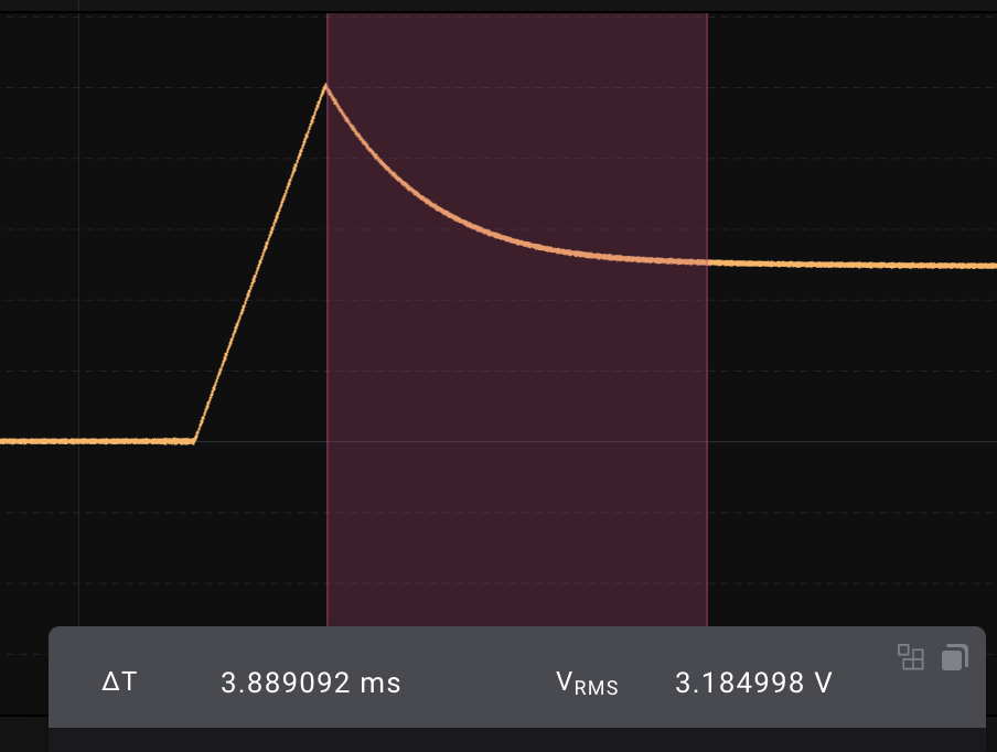
Decay to center is 3.9ms

Decay to bottom is approximately the same


Decay to 75% too


Release is in the same range, looks like approximately 5ms.


At 15, attack is 3.83ms

At 31, attack is around 12ms, or 10 times the fastest

At 47, attack is 38.3ms

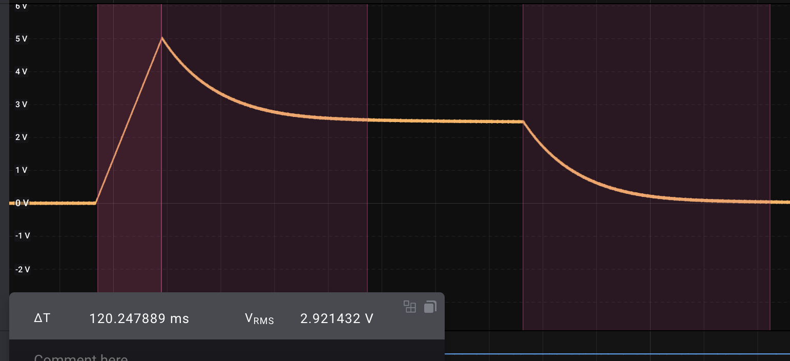
At 63, the envelope looks like this:


Attack is 120ms, decay around 385ms and release around 460ms, pretty much exactly 100 times the fastest.


At 95, Attack is 1.2s and the others are similarly 100 times the shortest. Something interesting to note too is that the envelope keeps dropping even after the initial decay...

In other words, we have exponential growth from 1ms to 10s, quite expected really :)

(The actual transfer function is f(x) = A*10^(x/32), where f(x) is the level, A is the time at X=0 (1.2ms if we cheat a little) and x is the midi value).

The manual says the ranges for all stages are 1 to 10s. It seems that this is not quite correct for decay and release, but attack is definitely close.


One final thing - sample & hold

Oh, and a little thing I noticed while studying the Slim Phatty schematics - Sample and hold buffers use 1nF caps and LF353, multiplexed through DG408s. The signal looks more noisy than what I get, but that is though a long signal cable. The dac is DAC8581, which has a settling time of 0.65uS for a 10V change.

Friday, June 11, 2021

Envelope stage curve calculations

For the XM8 we want different response curves to choose from for each stage. By default, the stage is linear. We then use lookup tables to get other responses.

Each curve is stretched in time and amplitude by the envelope code, so the only requirement is that a curve starts at (0,0) and ends at (1,1) (or, for ease of use here, starts at (0,1) and ends at (1,0).

Below are the general formulas for three types of curves - squared, exponential and logarithmic. As neither exponential nor logarithmic will pass through the necessary points by default, we add a multiplier and a constant to fit the curve. In addition, we add a parameter that can change the steepness of the curve to give the user some variation (the Andromeda A6 has three exponential and three logarithmic to choose froom.

The Modor synthesizer also has the option of using squared reciprocal and reciprocal. I've dropped these in favour of multiple variations of the others. 


General goal


We want various curves that go from (x, y) = (0, 0) to (1, 1),  or from (1,0) to (0,1):


Squared

A rising variant, going from (0,0) to (1,1), would be

y = x^2

The falling variant, going from (1,0) to (0, 1) would be

y = (1-x)^2 

These functions already fulfill the requirements.


Exponential

General exponential functions can be written as

y = ae^(bx) + c


where

- a transposes along x

- c transposes along y

- b selects steepness. Larger b = steeper curve

b chooses the "steepness" of the curve.


To solve, select a value for b and solve two eqations using the coordinates of the start and end points.


The solution for a rising curve is:

a = 1 / (e^b - 1)

c = -a

https://www.desmos.com/calculator/qquhqjlrjv


The solution for a falling curve is:

a = 1 / (1 - e^b)

c = (1-a)

https://www.desmos.com/calculator/73ufmkfxlb


Approximate values for b used by the Andromeda: 2.2 ("normal", exp 1), 4.4 (exp 2), 5.5 (exp3)


Logarithmic

For same range:

General formula

y = log(x+a) / b + c

where

- a transposes along x

- c transposes along y

- b selects steepness. Larger absolute value for b equals steeper curve. (positive values for rising curve, negative for falling)


The general solution:

Rising: (x, y) = (0, 0) to (1, 1):

a = 1 / (10^b - 1)

c = -log (a) / b

b > 0

https://www.desmos.com/calculator/tyfhantqj8


Falling: (x, y) = (0, 1) to (1, 0)

a = 10^b / (1-10^b)

c = -log(1+a) / b

b < 0

https://www.desmos.com/calculator/s9wahlimnm

The andromeda looks like it uses a b of approx 1.3, 1.7 and 2.2


For the natural logarithm, ln, the solution is:

y = ln(x+a) / b + c


Rising: (x, y) = (0, 0) to (1, 1):

a = 1 / (e^b - 1)

c = -ln (a) / b

b > 0

https://www.desmos.com/calculator/wxkxquiaqn

The andromeda looks like it uses a b of approx 3, 4 and 5


Falling: (x, y) = (0, 1) to (1, 0)

a = e^b / (1-e^b)

c = -ln(1+a) / b

b < 0


PS: The log and ln functions look exactly the same, only b varies.


Usage in envelope code

Our envelope lookup code uses 16bit unsigned ints, so both the x (time) and y (amplitude needs to go from 0 to 65535. This is easily achieved by dividing x with 65535 and multiplying the whole expression with 65535, ex:

y = 65535 * (ae^(-bx/65535) + c)


All testing was done with https://www.desmos.com/calculator


Wednesday, January 27, 2021

Trying to create a CV curve to convert exponential VCA to linear.

In this post I'll try to explain exactly how the xxx2164 (SSM2164, v2164, AS2164 etc) responds to CV and how it (in theory) can be linearised when controlled digitally. I've written V2164 throughout the post as this is the chip I have at hand, but they should all be similar.

NB: I write my math as I go along, so it reflects my way of thinking. It may not be the most direct route to the final result, nor the best way of explaining, but at least I think the results are correct

Whether or not the results are useful in practice are to be seen. The V2164 is temperature sensitive and may not follow the stated -0.033V/dB response at all (or indeed any) temperature. There may also be differences between chips, and the DAC resolution may not be high enough to prevent stepping even when using 16bit DACs.

The V2164 

V2164 has a -33mV/dB response, meaning a 33mV increase leads to a 1dB attenuation.

When using the V2164 with a 3.3V control signal, I realised that it very quickly gets very quiet and thus it's hard to set the exact gain/ attenuation that you want. As mentioned here, the usefull CV range is 2V which results in 2V / 0.033V = 60dB attenuation.

The signal amplitude is doubled/halved for every 6dB change (0.2V in our case) as noted here. That would as far as I understand, mean that the signal is halved 10 times at 2V. With a +/-5V signal input, output would be

$$((((((((((5 / 2) / 2) / 2) / 2) / 2) / 2) / 2) / 2) / 2) / 2) = 5 / 2^{10} = +/- 0.0049V$$

But what is the function / relation between CV and VCA response?


Decibel - change in amplitude 

At any time, the increase in dB between two levels \(a_0\) and \(a\), can be written as

$$d = 20 \cdot log_{10}({a \over a_0})$$

where \(log_{10}\) is the 10-logarithm. From now on I'll write just \(log\)

For example, if the initial amplitude a_0 was 1V and the new level a was 2V, the increase would be

$$d = 20 \cdot log({2 \over 1}) = 6.02dB$$

which is indeed what we said above - a doubling of amplitude is the same as a 6dB change. Let's confirm this with our calculation above - going from 0.0049V to 5V:

$$d = 20 \cdot log({5 \over 0.0049}) = 60.2dB$$

So, how can we rewrite the formula to represent the relationship between our CV and output amplitude?

Let's first express the amplitude change as a function of change in dB

$$d = 20 \cdot log({a \over a_0})$$ $$10^{({d \over 20})} = 10^{log({a \over a_0})} = {a \over a_0}$$ $${a \over a_0} = 10^{({d \over 20})}$$

Taking it one step further to make it easy to plot, we move \(a_0\) to the other side:

$$a = a_0 \cdot 10^{({d \over 20})}$$


Let's check with our initial ratio:

$$a = 1 \cdot 10^{({6.02 \over 20})} = 2$$

Just as expected. Here is a plot of this function:

X is change in dB, Y is amplitude. We can see that the initial amplitude is 1 and that 6dB gives an amplitude of 2. Increasing dB by another 6dB to 12dB shows another doubling of amplitude to 4


From decibel formula to CV response

One final step is necessary, we need to go from the general equation for change in decibel to response to our CV. This should be fairly easy. We know that the response is -0.033V per dB (note: negative volt, i.e. a voltage increase leads to attenuation, not amplification):

$$d_{dB} = {v_{V} \over {-0.033_{V \over dB}}}$$

which gives us a as a function of v volts:

$$a = a_0 \cdot 10^{({{v \over {-0.033}} \over 20})}$$ $$a = a_0 \cdot 10^{({v \over {-0.66}})}$$


Let's check:

Increasing the CV with 0.033V should attenuate the signal 1dB, meaning that a 0.2V signal should attenuate the signal 6dB, which means halving the amplitude. We choose 1 as the initial amplitude, because with CV = 0 the V2164 should have unity gain. While at it, let's rename amplitude a to gain g as that is really what we're talking about when it comes to the VCA:

$$g = g_0 \cdot 10^{({v \over {-0.66}})}$$

\(g_0 = 1\) (unity gain when CV is 0) gives us

$$g = 10^{({v \over {-0.66}})}$$

and finally

$$g = 10^{({0.2 \over {-0.66}})} = 0.5$$

Again, as expected. Here is a plot of the function:

X is CV in volts, Y is gain (unitless). As expected, the signal starts at 1 when the CV is 0, and drops exponentially when the CV increases. at 0.2V the gain has halved to 0.5


Finding the equation for a linear response

Great! Now we know what we're up against. Next, we need something that takes a number - our internal linear control signal, let's call it c - and converts it into something we can input to the VCA CV to counter the function above. We need something that increases it's drop at the same rate as the function above decreases its drop.

So let's see what we've got.


We want the following to be true:

$$10^{({f(c) \over {-0.66}})} = k \cdot c$$

where k is a constant (rate of change, stigningstall in norwegian), in other words, we want something that makes our exponential function linear. We already know that \(f(c) = v\) from our definition, so let's use that.


Now we need to figure out what the relationship between v and c is:

$$log(10^{({v \over {-0.66}})}) = log( k \cdot c)$$ $${v \over {-0.66}} = log( k \cdot c)$$ $$v = -0.66 \cdot log( k \cdot c)$$

This works fine for positive k (e.g. rising linear response), which is what we usually want. However, after \(k \cdot c = 1\) it becomes a negative number which we cannot represent directly with a DAC. Also, when \(k \cdot c = 0\), \(log(k \cdot c)\) is infinite, which means we can never really reach all the way down to 0 gain using an exponentially controlled VCA.

As x approaches 0 from above, y approaches infinity. When x (or rather \(k \cdot c\) in our case) is > 1, y is negative.


Combining the equation for v with our equation for g yields exactly what we want - a linear response (rate of change k times control signal c on the horizontal axis, gain g on the vertical).


For a negative k (e.g. falling response), \(log(k \cdot c)\) is not defined for positive control signals c as \(k \cdot c\) is a negative number. To still be able to use a positive control signal c to represent a falling curve, we need to add something to offset our zero point: \(log(p + k \cdot c)\) where p is the desired gain at c = 0 (e.g. what we get when we set c to 0 and combine our two equations). 

The combined response is not defined for positive values of c when k is negative. 

Adding a constant "shifts" the graph to the right. Here p is 2 and k = -0.5: we get a gain of 2 when c is 0 and a gain of 0 when c is 4. NB: This is just in theory, as explained above we cannot reach g = 2 for c = 0 because the logarithm approaches infinity. More on that further down.


p may still be present for positive values of k, however the same limitation applies - if \(p + k \cdot c < 0\) the result is not defined, and if \(-0.66 \cdot log(p + k \cdot c)\) is negative it cannot be represented directly by a DAC.


Our relation between c and v is thus:

$$v = -0.66 \cdot log( p + k \cdot c)$$

with the limitations

$$p + k \cdot c >= 0$$ $$log(p + k \cdot c) < 0$$


Using this in our equation for the VCA gives us

$$g = 10^{({{-0.66 \cdot log( p + k \cdot c)} \over {-0.66}})}$$ $$g = p + k \cdot c$$

which is indeed a straight line with gain p at \(c = 0\) and gain 0 at \(k \cdot c = -p\)


How to use this in practice

Now, we still have the issue of not being able to reach g = 0. We need to look back at what we said in the beginning, the effective CV range of the V2164 is 0 to 2V, and at 2V it has an attenuation of 60dB (or gain of -60dB). This is what we should use as our minimum value for g. The maximum value should be whatever we want as our maximum gain, noting that unity gain (g=1) is the highest we can get using a DAC directly connected to the VCA.

We need to know exactly what we mean by -60dB in this case. Here, it means -60dB down from unity gain. A change in dB from an initial value of a_0 to a new value a is written as 

$$d = 20 \cdot log({a \over a_0})$$

For us, \(a_0\) is 1 so 

$$20 \cdot log(a) = -60$$ $$log(a) = -3$$ $$a = 10^{-3} = 0.001$$

Let \(c_{start}\) and \(c_{end}\) be the two extremes for our control signal:

This gives us two equations from \(g = p + k \cdot c\)

I) \(g_{start} = p + k \cdot c_{start}\)

II) \(g_{end} = p + k \cdot c_{end}\)

We can now pick our \(g_{start}\), \(g_{end}\), \(c_{start}\) and \(c_{end}\) to find k and p.

Let's give two examples based on whether we want a rising or falling response to our control signal. We choose to use volts as the unit for our control signal and set 0V to 5V as the range. We could also choose the range to match whatever representation we use in our code, for example 0 to 65535 if we represent the control signal as an unsigned int.


For rising control signals

\(g_{start} = 0.001\), \(g_{end} = 1\), \(c_{start} = 0V\) and \(c_{end} = 5V\)

I) \(0.001 = p + k \cdot 0 => p = 0.001\)

II) \(1 = p + k \cdot 5V\)

I + II) \(k \cdot 5V = 1 - 0.001 => k = {0.999 \over 5}\)

Finally, we insert this into our formula for v, \(v = -0.66 \cdot log(p + k \cdot c)\)

\(v = -0.66 \cdot log(0.001 + {0.999 \over 5} \cdot c)\)

Our desired response. A 0 to 5V CV gives a gain of 0.001 to 1

For falling control signals:

\(g_{start} = 1\), \(g_{end} = 0.001\), \(c_{start} = 0V\) and \(c_{end} = 5V\)

I) \(1 = p + k \cdot 0 => p = 1\)

II) \(0.001 = p + k \cdot 5V\)

I + II) \(0.001 = 1 + k \cdot 5V => k \cdot 5V = 0.001 - 1 => k = \frac{-0.999}{5}\)


It should come as no surprise that k is indeed the negative version of the result for the rising control signal, the absolute value of the rate of change is the same for both.

Again we insert this into our formula for v, \(v = -0.66 \cdot log( p + k \cdot c)\)

$$v = -0.66 \cdot log( 1 + \frac{-0.999}{5} \cdot c)$$

Increased attenuation as CV increases. 5V CV gives a gain of 0.001

From CV seen at the VCA to signal that controls the DAC

We have one final step to make all this useful.

We have from the start assumed that whatever we are working with outputs voltages directly from our control signal, and that our \(c_{end}\) outputs exactly 2V. 

This of course is not true for a DAC. We can choose to use a DAC in two ways:

  1. We use a reference voltage of 2V. The max DAC value is then 2V
  2. We use a different reference voltage, say 5V, and use external circuitry to change this into our 2V.

In both cases, we need to know what DAC control signal results in 1V at the VCA control input

Ex: 

If we're using a 16bit DAC and a 2V reference, 1V is represented as 65536 / 2 - 1

If we're using a 16bit DAC and a 5V reference, 1V is represented as 65536 / 5 - 1


Let s be the DAC control signal, \(s_{1V}\) be the DAC control signal value that results in 1V at the VCA input, and v the output voltage seen at the VCA CV input. The relationship between v and d is then

$$v = \frac{d}{s_{1V}}$$


Entering this into our expression for v, \(v = -0.66 \cdot log( p + k \cdot c)\), gives us

$$\frac{s}{s_{1V}} = -0.66 \cdot log( p + k \cdot c)$$

$$s = -0.66 \cdot s_{1V} \cdot log( p + k \cdot c)$$

There is a possible pitfall to be aware of. How well the effort to linearise the VCA works in practice depends on the DAC resolution. The VCA attenuation increases rapidly in the beginning, a very small voltage change gives a huge attenuation. If the DAC resolution is not high enough, each step changes the voltage too much and we will get audible stepping for slow moving CVs.


Summary of useful results

The general equation to linearise the response of the V2164 is

$$s = -0.66 \cdot s_{1V} \cdot log( p + k \cdot c)$$

where 

  • \(s\) is the DAC control signal value, possibly an unsigned int for a 16bit DAC
  • \(s_{1V}\) is the DAC control signal value that gives 1V at the VCA input (e.g. 65536 / 5 - 1 with a 5v reference)
  • \(p\) is the desired VCA gain at c = 0
  • \(k\) is the rate of change (gain / control)
  • \(c\) is our internal control signal with a unit of our choosing
\(p\) and \(k\) are found by selecting min/max gain and min/max control signal values, and solving the following two equations with two unknowns:

I) \(g_{start} = p + k \cdot c_{start}\)

II) \(g_{end} = p + k \cdot c_{end}\)

In practice, gain can never reach 0. For a positive k, p must be > 0. For a negative k we need need to use a g_{end} > 0.

Remember

- k changes when we change between volts and int value for our internal control signal.

- c and s do not have to use the same units

- c is assumed to be positive in all calculations above, but it may very well be possible to use negative values here. I just haven't checked.

- low DAC resolution will lead to audible stepping


Further thoughts

If I remember correctly, the V2164 allows gain > 1 by using a negative CV.  Without actually trying, I would think that using the equations above would suffice for this as well. If you want to add 3dB of extra gain, just extend the desired attenuation down to -63dB and then add - 0.1V (3  * -0.033V) to the DAC output to shift everything 3dB up. I have not tested this though.

To linearise a different VCA with a different response, "just" replace -0.033V/dB in the initial equation for the CV response and the resulting linearising equation. The general cases are:

Let b be the CV response in volts per dB (-0.033V/dB for the V2164). We then get that:

gain as a function of CV is:

$$g = g_0 \cdot 10^{\frac{v}{b * 20}} $$

necessary linearising equation is

$$v = 20 \cdot b \cdot log( p + k \cdot c)$$

and the DAC control value for producing that v is

$$s = 20 \cdot b \cdot s_{1V} \cdot log( p + k \cdot c)$$


The end. Time to try this in real life!


Footnote: All graphs are made using https://www.desmos.com/calculator


Friday, January 22, 2021

Exponential VCA v2164 and CV response

A quick note on the effect of a linear CV on the V2164. I connected a pot between 3.3v and 0. When turning the pot, nothing is heard until the pot is 2/3 of the way to max (CV drops from 3.3 to 0 as the v2164 expects a reversed CV, 0 being max on/unity gain).

Measuring the CV at this point shows as expected, around 1.2V. This means that for the rest of the pot's travel, it has no audible effect. This further strengthens my belief in using linear VCAs for the XM8. Alternatively, one could use a 0 to 1.5v cv, but it will never fully turn off the VCA. 

I'm looking forward to testing the same with a CEM3360/AS3360


Update: This article says that the effective CV range is 2V, which is more like what I experienced:

http://www.sdiy.org/philgallo/mgbvca.html

Tuesday, January 19, 2021

Envelopes, VCAs and linear vs exponential

TL;DR: 

  • Use linear VCAs when controlling them digitally, even when controlling audio. That lets you generate whatever control slope you want in software.
  • The VCA response is always exponential, not logarithmic. The only time we're actually talking about something looking more like a logarithmic response is in classic "RC" envelopes where the attack part is more logarithmic. Logarithmic control signals are generally only used to linearise an exponential VCA.

The full text

Through testing the digital envelopes in combination with the v2164 VCA, I realised that all is not good. It was particularly hard to dial in the sustain level as it dropped so fast when turning the pot due to the exponential nature. This made me realise that I had to revisit the topic of envelopes to fully understand how it is done in practice.

My initial confusion stems from the fact that people keep saying that you should use exponential VCAs for audio because they more closely approximate the way our hearing works. While this may be true when using the VCA as a volume control alone, it isn't necessary true elsewhere in the synth.

There is a lot of confusion about the use of the terms log(arithmic) and exp(onential) in the synth world, both when talking about potentiometers, VCAs and envelopes. I'll not go into detail, but just conclude that the slope/response is almost always exponential, not logarithmic. The only time we're actually talking about something looking more like a logarithmic response is in classic "RC" envelopes where the attack part is more logarithmic, and even here it is just an exponential response turned "upside down" (charging a cap instead of uncharging it). Logarithmic control signals are generally only used to linearise the response of an exponential VCA.

Another thing that is repeated is that using an exponential envelope with a linear VCA is the same as using a linear envelope with an exponential VCA. That is almost true, but with an exponential envelope controlling a linear VCA, you get direct control of the sustain level whereas when a linear envelope controls an exponential VCA, we get the "mapped" version of the sustain level which is significantly lower than the control voltage - which may be what you want but I found it hard to actually get the necessary control.

There's another point to be made though. When people talk about exponential envelopes, I suspect they mean the classic ones that is the result of charging and discharging capacitors, "RC" response. Those have a rapid increase upwards at the start of the attack and a rapid decrease at the start of decay. Using a linear envelope with an exponential VCA would give you a slow attack. 

A better name for the stages in an "RC" response envelope seems to be concave upwards and concave downwards. This is not what you get with an exponential VCA controlled by a linear envelope. 

Top: A linear envelope. Middle: The effect of feeding the linear envelope above through an exponential VCA. Note that the attack slopes downward and that the sustain level is significantly lower than the linear input as an exponential VCA drops very fast in the beginning. An exponential envelope would have the same shape but you would of course control the sustain level directly. Bottom: "RC" response, the classic envelope shape you get from charging/discharging a capacitor.


A lot of other versions exists. When you dive into the realm of digitally generated envelopes you find stuff like the Alpha Juno multi stage envelopes where the slope changes on a per-stage basis.

Alpha Juno lets you set envelope by specifying Time and Level for each stage. Slope varies from stage to stage, sometimes being linear (1, 2) and sometimes exponential (3, 4). These envelopes are purely digital.


One question was still unanswered for me - with an exponential envelope, should one make it control an exponential or a linear VCA? I've concluded that it has to control a linear VCA. The issue with sustain level speaks clearly of this. You want the response of the envelope, not an exponential version of it - especially when doing digital envelopes as you can pretty much do whatever shape you like. Hopefully, the resolution of the CV is high enough to mimic exponential growth with a fairly good quality even at low volumes.


What VCA chip to use in the XM8

Having to use linear VCAs kind of sucks. I was hoping to use the v2164 quad VCA extensively because it offers four VCAs in a compact package and at a reasonable price. If envelopes should control linear VCAs, and if I want to be able to patch envelopes anywhere, I also need to use linear VCAs everywhere. My best option seems to be the AS3330, which is a dual lin/exp VCA costing almost twice that of the V2164 meaning I have to spend four times as much on VCAs. That in itself kind of suck, but it will also take twice the space on the PCB which REALLY sucks. 

I will give the V2164 a final try though. If I can generate a logarithmic control signal, the output response will be linear. There is a very standard circuit going around that does this by combining two 2164s, but that sort of defeats the purpose. I have to do it digitally. This may result in very low resolution for the higher volumes, we'll just have to see.

Update: AS3364 is a quad linear VCA, that may be a good option. Unfortunately it's +/- 12V, not 15. I've ordered 10 of them for testing. I also realised that I have both AS3330 and AS3360 chips that I can try if I want. The AS3364 seems to be a dual AS3360 but with the exponential inputs removed, the text and specs in the datasheet is almost identical. This is good as it makes it possible to replace the AS3364 (which is an Alpha Rpar specific chip) with two 3360s on an adapter board later, should one fail and no replacements be available.


Resources

https://www.muffwiggler.com/forum/viewtopic.php?t=217707

https://www.muffwiggler.com/forum/viewtopic.php?t=115675

https://www.gearslutz.com/board/electronic-music-instruments-and-electronic-music-production/984069-embarrassing-question-explain-alpha-junos-envelopes.html

https://musicianonamission.com/adsr/

https://www.muffwiggler.com/forum/viewtopic.php?t=102357

Tuesday, January 15, 2019

Juno filter: cap values and expo converter musings

After spending the last few weeks experimenting with the Juno filter, I have some thoughts. It seems the exact compnent values along the signal path are not terribly important to how the filter works. A lot of the filter is tweakable as we've seen in my previous posts - the input CV ranges, the VCA gain etc.

I have tried various cap values as well, and today I made a comparison of both cap values and changes to the expo converter.

Expo converter

The expo converter core is dependent on a reference current. Right now that is set up using a 1.5MOhm resistor, but changing this does not change the output curve, it only changes WHAT linear CV gives what output.

I tried swapping for a 1MOhm resistor, and using the base octave trimmer I could still get the necessary output range. Here are the currents through a single I_abc resistor:

Using 1.5MOhm resistor, the output current is:

Full trim and 5V CV range: 3.2nA to 1.377mA
Center trimmed: 165nA to 168uA

Using 1MOhm resistor, the output current is:

Full trim and 5V CV range: 4.9nA to 1.379mA
Center trimmed: 248nA to 238uA

The center trimmed range is well within the total range independent of resistor, with room to spare for additional octaves.

Filter caps

The Juno 106 uses 240pF caps, other Roland synths use 330pF, and we use 270pF. Here are the responses to a center trimmed CV using a 1.5MOhm reference resistor:

240pF
0V = 7.7Hz
5V = 6.4kHz
10V = 42kHz

270pF: 
0V = 7Hz
5V = 5.7kHz
10V = 39kHz

330pF
0V = 6.1kHz
5V = 4.7kHz
10V = 34kHz

Note that at 10V all of the outputs are at their max (I_abc is 1.38mA) so tracking is off. But all filters reach well above 20kHz. If one aims for a 40k cutoff 240pF and 270pF seem equally suited.


Wednesday, December 27, 2017

YAC, a DAC (floating point)

I started looking for Yamaha OPL2 (YM3812) and OPL3 (YMF262) chips on ebay yesterday, as I thought it would be nice to get some for future use. These vintage FM chips were everywhere in the late 80's and early 90's, particularly on Adlib and SoundBlaster sound cards.

I soon realised that one needs an additional chip - a DAC - as the chips are completely digital.

The DACs used are YM3014B for the OPL2 and YAC512 for the OPL3. Both are serial input DACs with what they call 16bit dynamic range. But they are not 16bit integer DACs. So what are they?

They are in fact floating point DACs, with one "normal" integer DAC (10bit), called the mantissa, and an exponential multiplier, the exponent, that sets the reference voltage. This is just like a floating point number which has a significand (the mantissa) and a base raised to the power of an exponent.

As the exponent changes, the width of each step of the 10bit DAC changes. This means that at the resolution is higher at the lower end of the scale, and it decreases (the step width increases) as one moves upwards.

The circuitry is presumably along the lines of this (though this patent is from 1990 and the YM3014B is much older than that), though the Yamaha datasheets call the exponential part an analog shifter:
Floating point DAC patent
The YAC512 supports two time multiplexed outputs from a single DAC through external sample and hold capacitors. The YM3014B is single channel and requires no sample and hold.

I wonder if it would be a good idea to use such a DAC for my DCO - it seems to be available for less than $1 a piece on ebay, though I'm not sure if those are fakes or not. The exponential nature of the DAC should fit an exponential scale well.

Tuesday, June 16, 2015

Exponential curve using lookup table

It has been a while since my last update. My daughter arrived on Norway's national day, the 17th of May. It's so incredibly nice and I am the proudest dad ever! It does take the focus away from other things though :-)

Just before she arrived, I bought a book from 1980, musical applications of microprocessors. It may sound outdated but in fact is a treasure - it explains lots about sound theory, filters, DAC and ADC etc.

Today I am reading about generating waveforms digitally. Since the book is from 1980, the available computers were incredibly slow, worse than many of today's microcontrollers. This is a plus, since it means it explains a lot of neat tricks to make things run faster.

For example, it shows how to generate a sine wave using a small lookup table and doing linear interpolation between the points (p. 388). If certain criteria are met, the task only requires two subtractions, an addition and one multiplication.

In the OMM, I intend to do linear to exponential conversion using a lookup table. With 16bit values this would require 128kB for a full table. This can be reduced dramatically if I accept a little inaccuracy and use the same interpolation. As long as the result is not used for controlling the frequency of a vco, it should not be much of a problem

Saving space would also allow me to implement for example both 50dB and 70dB curves etc.

Sunday, January 11, 2015

Exponential VCA with temperature correction

As promised in the previous post, here is a new take on the exponential VCA. This time the CV input has been modified and a tempco resistor added. This is the same scheme used in many VCOs for the pitch CV.

As the 1k 3300ppm tempco resistor is the most used tempco resistor in DIY designs, possibly making it easier to get hold of, I have decided to use it for this design as well. This, however, means that the input CV has to be amplified before it is attenuated by the resistor voltage divider formed by R21 and TR1.

There are two ways to build this circuit - trimmable and not trimmable. For the not-trimmable version, use the exact values found in the diagram - 57k (47k + 10k) on the CVTRIM input and 23k (22k + 1k) in the feedback loop. All resistors should be 1% or better metal film resistors.

For a trimmable version you may replace the CVTRIM input resistors with a 10k resistor. The input voltage should be around -2.6V, and you may connect a 20k or 25k potmeter between 0 and -15V to achieve this. This potmeter will subtract a voltage from the input CV, which affects the maximum and minimum amplification possible. Both move in the same direction, if the maximum drops, the minimum will also get lower.

You may also change R11 to a 18k resistor and R19 to a 10k potentiometer. This pot will affect the "distance" between the maximum and minimum amplification. Turning the potmeter to the right and increasing the resistance of R19 will make the maximum amplification drop, but at the same time the minimum gets higher (i.e. you will not be able to attenuate the signal as much).

CV (linear) and response (Exponential) without trimming. No tempco used but temperature is 24 degrees celcius. Trim voltage is -15V, not 15V as it says in the picture.


The maths behind this

The maximum input to the transistor base when no correction CV is added should be -0.2072V. Using the R21/TR1 resistor voltage divider means that the output from the IC1A opamp must be -11.8V.

This voltage should be reached when the CV is 5V, which means that the CV has to be amplified -11.8V/5V = -2.362 times.

We will almost achieve this if we select a 23k feedback resistor and a 10k input resistor.

To reach -70dB, the correction CV must be 0.106V at the transistor input. This means it has to be 6.042V at the opamp output due to the resistor voltage divider. If we  choose to input -15V at the CVTRIM input, we need an input resistor (R1+R3) = 23k * -15V/6,042V = 57.1k

Or

If we choose a 10k CVTRIM resistor, the input correction CV must be 6.042V * -10k/23k = -2.63V


UPDATE: As pointed out by MB in the comments, there is an error in the schematics. The output from IC1A/B should go to the top of the 56k resistor and the Q1/Q2 transistor bases should be connected to where the 56k meets the 1k tempco, as shown in my original sketch here:


Saturday, January 3, 2015

Exponential VCA, first try

After getting a very good result from the linear VCA, I felt like making an exponential version as well. The Lockbox VCA has an exponential converter, so why not try to use the same thing here?

I have written a long text about the exponential converter and learned a lot about it, so I had everything I needed in terms of theory ready. Reading this will give good insight to why the exponential converter is like it is and how it works, but it is not necessary to follow the reasoning in this post.

The most important result from the document is that the output current from the converter, Ic, can be written as:

   Ic = Is * e^(Vb/Vt)

where

  • Is is a constant reference current
  • Vb is the voltage at the base of a transistor in the converter, which is a fraction of the CV.
  • Vt is a constant that - unfortunately - changes with temperature.


The exponential curve

My big question when I started looking at the exponential VCA was how exactly the exponential curve should be. Where should it start?

Now, this may sound strange, one would always like the control current to be 0A when the CV is 0V, and at its maximum when the CV is at max. Unfortunately, the formula above will NEVER be zero. When the CV is 0V, e^(Vb/Vt) equals 1, and so Ic = Is. We may add a negative voltage so that e^(Vb/Vt) becomes less than one, but it will still never be zero.

The question then is, how close to zero do we have to get before we cannot hear the signal passing through the VCA any more?

Offness

I tried some component values and looked at the result on the scope. It looked good, but when I tried connecting the output to an amplifier, I could easily hear the sound even when the CV was 0V. After some googling, and realising that I had what I needed in my bookshelf, I discovered a few nice rules.

Douglas Self writes about this in the chapter "Volume and Balance control" of his book "Small signal audio design".

He states that a good volume control should cover at least 50dB, and at least -70dB attenuation is needed to get a good "offness", where you cannot hear much of the signal any more. But what the heck does that mean?

I will not go into details about decibels, but here is a rule of thumb: If you increase a signal 10 times, you have raised the volume by 20dB. Increase it a 100 times and you have raised it by 40dB. Similarly, divide the signal 10 times and you have decreased it by -20dB. Divide it by 100 and you have decreased it by -40dB.

Volume controls (and VCAs) work by attenuating the input signal. The input should be at its highest and the volume control only "pinches off" parts of it, reducing the volume. So, as a consequence of the previous paragraph, when the volume is reduced to 1/10th of the initial volume, it has been reduced by -20dB.

To figure out how much -50dB and -70dB are, we can use the formula

   Change in dB = 20 * log(Output/Input)

Where log is the 10-logarithm.

Refactoring the formula gives us that

   Output = Input * 10^(Change in dB / 20)

At -50 dB:

   Output = Input * 10^(-50 / 20) = Input * 0,00316

At -70 dB:

   Output = Input * 10^(-70 / 20) = Input * 0,000316

In other words, the output is 0.00316 times the input when reduced by -50dB and 0.000316 times the input when reduced by -70dB. So, now we got something to aim for.

What attenuation to aim for

So, should you go for the -50dB or -70dB slope? Well, that depends of course. I have build both, and there is a significant difference in the offness. There is a faint but clearly audible sound from the -50dB VCA even when the CV is at 0. With the -70dB VCA I had to walk up to the speaker and put my ear next to it, and even then could only hear an extremely low sound (my wife actually heard it before me).

The problem with the -70dB contra the -50dB is that what you gain in offness, you lose in fine control of the higher-volume parts. You have to turn the volume pot of the -70dB one a bit before you reach the starting point of the -50dB one so you get less pot travel for controlling the rest. The difference is not extreme but it's necessary to be aware of it.

I would probably go for the -70dB, but if you do not need the output to be completely off (maybe the output is masked by the output of other sounds?) you may choose the -50dB version.

-50dB curve. Straight line is CV, 0 to 5V. Curve is response of a 5V input signal. Note: not finely adjusted so top misses 5V a bit.
-70dB curve. Straight line is CV, 0 to 5V. Curve is response of a 5V input signal. Notice how the bend is sharper and starts later than on the -5dB one.

Calculating vital parameters

We already know from the linear VCA that a maximum control current of 1.515mA will give unity gain within the circuit used, so we'll use that as a starting point. I will only show calculations for -70dB, but it is similar for -50dB and -100dB.

With a maximum current of 1.515mA, the minimum current must be

   0.000316 * 1.515mA = 0.479 uA for -70dB attenuation.

To see what this means for input CV voltage, we need to use the exponential formula again.

Remember,

   Ic = Is * e^(Vb/Vt)

which means that

   Vb = Vt * (ln(Ic) - ln(Is))

Vt varies with temperature, it is in fact

   Vt = ((degrees in celcius +273.16)*1.38*10^-23) / (1.6*10^-19)

This means that at 20 degrees celcius ("room temperature"), Vt = 25.3mV

Is is a constant that we choose ourselves. From my initial trials I found that an Is of 15V / 510kOhm = 29.4uA worked fairly well, so I chose that for my further calculations

Now we  can find Vb:

   At 0.479uA, Vb = 25.3 * 10^-3 * (ln(0.479*10-6) - ln(29.4*10^-6)) = -100.6mV

   At 1.515mA, Vb = 25.3 * 10^-3 * (ln(1.515*10-3) - ln(29.4*10^-6)) = 96.27mV

In other words, the voltage span needed to control the VCA from 0 to -70dB is

   96.27mV - (-100.6mV) = 196.8mV

Ah, but our CV spans 5V, and it starts from 0, not -100.6mV? Well, that can easily be corrected by an opamp summer with gain < 1.

By using a 1k feedback resistor and a 25k input resistor, our 5V CV is reduced to a 0.2V CV. To move the starting point to -100mV we only need to add a negative voltage. If we use the negative supply rail, -15V, we have to divide it by 150 to get to -100mV. As it has to run through the same 1k feedback resistor, we need to run it through a 150k resistor to get this attenutation.

A word of confusion

I have neglected to mention one thing. The exponential converter described above requires a positive Vb and it has its positive reference current Is and control current Ic running down into the collectors of the exponential converter transistors.

The output of the opamp summer connected to the CV circuit however, inverts the voltage giving us a negative CV. At the same time, the LM13700 requires a positive current running INTO pin1.

Fortunately, a PNP-transistor based exponential converter works exactly opposite of the NPN based one described in my texts about the exponential converter. Instead of a positive Vb it requires a negative one, and its reference current Is must run out of the collector. So by connecting the reference current generating resistor to -15V instead of 15V we are good to go.

Temperature is a bastard

Although we now have a working exponential VCA, it only responds accurately to the CV when the temperature is exactly 20 degrees celcius. This is because of the Vt mentioned earlier.

To see just how bad this gets, we can do some quick calculations:

TemperatureVtIc maxPercentage of 20 degrees
023.6mV2.02mA133%
1024.4mV1.74mA115%
2025.4mV1.52mA100%
3026.1mV1.33mA88%
4027.0mV1.18mA78%
5027.9mV1.05mA69%

This may pose a bit of a problem. It is likely that the temperature will be higher rather than lower than 20 degrees, so the current will probably never be too high. Still, it may be a good idea to add a trimpot to the voltage that moves the starting point so that you can adjust your VCA to work best at your desired temperature. This will also alter the maximum attenuation, but not dramatically.

An exponential converter that works better with temperature changes will be suggested later.


Suggested resistor values for -50dB, -70dB and -100dB:

attenuationGain, R15CV, R4Trim, R3Trim if variable voltage/pot.
-50dB1k33k292k220k
-70dB1k25k150k120k
-100dB1k18k84k275k

If a trim pot or variable voltage is connected to the CVTRIM input, use the resistor value in the last column. If not, connect CVTRIM to -15V.
Dual exponential VCA with -50dB attenuation, 0-5V CV