Showing posts with label envelope. Show all posts

Thursday, January 9, 2025

Modulation matrix thoughts

I have a working modulation matrix on my XM8 prototype. But something is missing and I haven't had the time to put my finger on exactly what.

Here is a more thorough walkthrough of what could/should be supported.

1) A destination may be modulated by multiple sources, each with their own amount/weight. The sources are summed (to give for example vibrato by modulating a pitch CV by an LFO and summing it with the original pitch)


2) A source may modulate any number of destinations. Again, for example, the LFO may modulate multiple oscillators at the same time etc.


Now, these are dead given. But then we have a more complex one

3) A source may modulate the amount of another source. For example, a separate potentiometer may modulate the amount of LFO applied to the VCO pitch.


Then we have a special case

4) Multiple destinations may control a function, which in turn is the source of another modulation. For example, multiple pots may control an envelope. The output of the envelope may modulate the output VCA.


Strictly speaking, we could also let the destination directly act as a source, leading to

5) Any destination may be treated as the source of another modulation


6) Any destination may be treated as the amout of another modulation


Right here it feels like we're entering FM territory...


Summed up into some general rules:

  • A modulation path consists of a source, an amount multiplier and a destination.
  • A source may modulate a destination or the amount of another source
  • A source may modulate multiple destinations or amounts 
  • A destination may be modulated by multiple sources. The sources are summed after being multiplied by individual amounts
  • Multiple destinations may act together to control a function (LFO, envelope)
  • Pots, destinations and function outputs may all act as sources

It would be a good idea to hardwire most pots to specific destinations

Most amount coefficients in the matrix will be zero. It may be better to have a list of 'active' modulations to reduce the number of coefficientds, but that depends on the MCU and what optimizations it may do on the data.

I think my major mental breakthrough here is that I realized that sources, especially pots, must be able to control the amount.

Things I still wonder about

  • Will it always be correct to add, not multiply, the various modulation paths?
  • For simplicity, should we really allow any destination to act as a source?

Oh, and here are some resources for Teensy math:
- https://forum.pjrc.com/index.php?threads/linear-algebra-library-for-teensy-4-1-robotics-project.69778/
- https://github.com/PaulStoffregen/Audio/blob/master/utility/dspinst.h
 

PS: Multiplying and summing two vectors (or matrices) is called a dotproduct.

Wednesday, February 16, 2022

Envelope time curve - midi mapping

After looking at the transfer function of the Little Phatty, I decided to redo the mapping for my XM8. In the same way as with the level function, I'd like to make it dynamically changeable, to be able to dial in the perfect transfer function per envelope.

The LP has an envelope time (per the manual) of 1ms to 10s (10.000ms).

The midi transfer function, with f(x) in ms, is thus

f(x) = 10^(x/(127/4)), for x=0 to 127


To get a changeable function, I looked at my previous work on envelope curves. I have a general function with built in steepness.

A function starting at 0,0 and ending at 1,1 with variable steepness can be written as

f(x) = a * 10^(steepness * x) - a

where

a = 1/((10^steepness) - 1)

Extending this to a case where we want a highest value for input and output, we get

f(x) = Y_max * ( a * 10^(steepness * (x/X_max)) - a)

where again

a = 1/((10^steepness) - 1)

Unlike the LP function, this starts at 0, since I use a 0-indexed time where 0 is the shortest possible time, around 1ms. If we want a different starting point, we get

f(x) = Y_min + (Y_max - Y_min) * (a * 10^(steepness * (x/X_max)) - a)


Sunday, February 13, 2022

Little Phatty envelopes

Envelope sustain level

I've been trying to make curves to map a linear pot to envelope sustain level. I've added a function that generates a dB-accurate mapping, with adjustable dB range, but I'm having a hard time dialing in a curve I find pleasing so I thought I'd have a look at what the Little Phatty does.

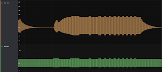
I took 128 measurements of the vol env output on my Little Phatty, one for each midi step. This is the result...


In other words, perfectly linear. I noticed that each step varies somewhat, so it is safe to assume that the internal resolution is much higher than 128.

Also, the pot is linear, midi 63 is straight up etc, so generated CV is 1:1 with the pot position.

The envelope CV feeds an LM13700 based VCA. It is in itself linear, but the control signal circuit may still change the envelope. I will have to simulate this to be certain, but since the envelope is in fact exponential in itself it is a good guess that control is still linear? But if so, the sustain level setting will not be very nice. I'll try that as well.


Update: Here is a plot of midi sustain value vs amplitude of a square wave:


It confuses me. In the beginning the output level increases rapidly, but then as we get higher the rate of change drops. But doesn't perceived loudness work the other way around?

Here is the plot overlaid on a recording of me turning the sustain pot fairly evenly:


It matches well so the curve is absolutely right. And it sounds ok too. In a way, it feels exactly like it looks, starting from the top things change fairly linearly until the pot is halfway (though it doesn't feel like it is HALF the volume. Then it drops much more rapidly.

I tried some new variations on my own synth. a 23dB curve, which (going down) ends at 2319, or 7% of max volume, sounds very linear to me. It is not fully off, so we may need to cap it at the lower end, which is exactly what the Little Phatty curve does - that one seems almost linear 3/4 of the way down. I tried doing something similar but it just doesn't sound good to me. I think I'll stick with the 23dB.

Closer look at envelope shape and times

While I had the LP hooked up I had a look at the envelope outputs. 


Shortest attack is 1.3ms, and the attack is linear

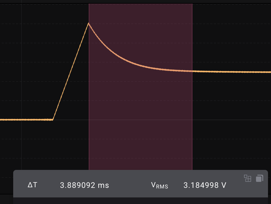
Decay to center is 3.9ms

Decay to bottom is approximately the same


Decay to 75% too


Release is in the same range, looks like approximately 5ms.


At 15, attack is 3.83ms

At 31, attack is around 12ms, or 10 times the fastest

At 47, attack is 38.3ms

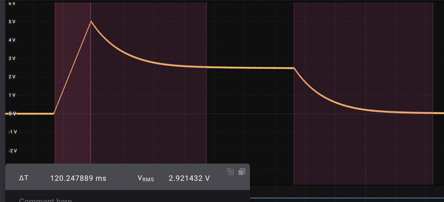
At 63, the envelope looks like this:


Attack is 120ms, decay around 385ms and release around 460ms, pretty much exactly 100 times the fastest.


At 95, Attack is 1.2s and the others are similarly 100 times the shortest. Something interesting to note too is that the envelope keeps dropping even after the initial decay...

In other words, we have exponential growth from 1ms to 10s, quite expected really :)

(The actual transfer function is f(x) = A*10^(x/32), where f(x) is the level, A is the time at X=0 (1.2ms if we cheat a little) and x is the midi value).

The manual says the ranges for all stages are 1 to 10s. It seems that this is not quite correct for decay and release, but attack is definitely close.


One final thing - sample & hold

Oh, and a little thing I noticed while studying the Slim Phatty schematics - Sample and hold buffers use 1nF caps and LF353, multiplexed through DG408s. The signal looks more noisy than what I get, but that is though a long signal cable. The dac is DAC8581, which has a settling time of 0.65uS for a 10V change.

Thursday, January 20, 2022

Voice card build and testing

I should really start off by screaming as loud as I can: "It's aliiiiiive!". This monday I hooked up a DCO, the waveshaper, a waveshape mixer, the Juno filter and an output VCA, all controlled by the voice controller and its internal modulation matrix. For the first time, I'm able to play my synthesizer using an external midi controller. It feels amazing! To think it took 7 years to get this far...

Anyway, it is not without bugs, but that's why I'm doing it this way in the first place, to test everything and how it works together.

There are a lot of things that work great right from the start. The waveshaper does its job perfectly, giving triangle, bi-directional saw, pulse with PWM and two sub oscillators with selectable square/saw output. 

The waveshape mixer CV generator I designed earlier works perfectly, as does the pulse wave amplitude control. 

The filter filters, though the range may be a bit lacking. It resonates beautifully too. I have yet to calibrate it and test it fully after moving from +/-15v to +/-12V. 

Finally, the output amp and envelope works great, though I had to fix a few rather hard to find bugs in my code.

Now, for each module, here are some things that must be fixed or improved.

Waveshaper

The sine wave amplitude is +/-4V while all the others are 5V. This can be fixed in the voice mixer by changing the input resistor or I can fix it on a new revision of the waveshaper.

The saw and triangle waves have noticeable ringing (noticeable on the scope, not necessarily audible). Adding caps in the feedback of the output will remove most of this. The rest goes away in the filter but I am not sure if it affects anything else. 

Pulse width: I don't think the pulse width is quite narrow enough.

When calibrating the symmetry of the sine wave, I can't seem to get a perfect setting that also gives a centered triangle wave. It is not a big issue though, but it means that the triangle is slightly "lower" than the other waveforms, perhaps by 0.5V or so. It is not audible, but it may affect how the circuit clips when mixing multiple oscillators. I'm going to leave it as it is for the time being.

The square wave sub oscillators are not centred. This is because the reference voltage used in centring is derived from -15V, and when changing this to -12V the reference is wrong. Again not audible but nice to fix.

The triangle and sine waves have a very visible notch at the end of the phase, more about that in the DCO paragraph.

Waveshape mixer

As I wrote in my last post, the AS3364 has a sort of dead band in both ends of the CV. Since all waveshape mixer CVs are generated from one input, it means that there is no way to compensate for this without changing the CV generator. In practice, the dead band means that one waveform fades out completely before the next one has reached its maximum. This is especially apparent in the saw to pulse cross fade, where the wave has become a square before the square has reached its top. It is not particularly pronounced so I don't think I'll do anything about it.

DCO

These are not properly wired up yet, so some of these things may go away - right now they run with the wrong calibration circuit and only produce a 0-5V wave when they should give us 0-10V (at least that's what the waveshaper expects). To compensate for this, I'm running the wave through a non-inverting op amp amplifier with 2x gain.

There are a few shortcomings/bugs in the DCO. First of all, some ringing is introduced along the way. I've added a cap to the feedback of the non inverting amp, a 15pF in parallel with the 56k resistor I'm currently using.

It looks like discharging the DCO cap goes too slowly. Either that, or we are limited by the slew rate of the op amps. In any case, this means that the drop from top to bottom of the saw wave is not instantaneous. When generating the triangle wave we invert half of the saw wave to get the "missing" portion of the triangle - but since the falling edge is not perfectly vertical, we get a notch at the end of the triangle phase. I can't say I hear it, but  at 8kHz it is very visible on the scope.
DCO discharge is not vertical enough, leaving a notch in the saw wave.

Adding a 5p cap across the DCO output op amp takes away much of the ringing at the start of each cycle


15p cap takes away even more of the ringing. Saw output from the waveshaper at the bottom, some new ringing has been reintroduced.

Clicking on envelope retriggers: When we play a new note without releasing the previous one, we get a bit of clicking. So far I've been able to identify two probable causes - output amplitude and centring after the filter, and glitches in the DCO.

The DCO glitches manifest themselves as discontinuities in the triangle wave, it suddenly and abruptly changes value. The reasons are:
  • When changing from a high to a lower pitch: It looks like the period timer is not reset. Instead, the period is reset when the original frequency would have been reset. This means the amplitude is too low and the start/end matching of the triangle fails.
Saw does not reach its maximum as it is reset at the "old" frequency
  • When changing from a low to a higher pitch: now the timer lasts too long, meaning the cap is charged more than it should. It reaches its max and flats out, both distorting the saw/tri and introducing a spike with too high amplitude. That would definitely sound like a click. 


The last of these is to be expected. The DCO is supposed to check the amplitude against a known voltage, but without calibration this won't work. The other one on the other hand, is stranger. I need to check the code.

I also got a more serious error while testing the very limits of the DCO. When playing OCT+4 on the MPK-25, switching between e and g makes the DCO drop to a much lower frequency for a single cycle before recovering. It happens consistently. No idea what makes it happen.


Finally, the range of the DCO is currently too narrow. It maxes out at around 8.5kHz but should reach at least the double or ideally above 20kHz. Replacing the integrator cap and regenerating the timer code will probably solve this.

Filter

As with the DCO, the filter cutoff range needs looking into. I have not tried calibrating the filter at all, so it may not be a real problem though, but it looks like the filter is not open enough with CV at 5v.

There is also something going on when changing the wave frequency. Obviously, when the wave frequency reaches the cutoff point, higher frequencies will be attenuated more, so with the filter at a fixed cutoff, switching between two notes will make the amplitude jump up and down. This may be part of the click-sound I'm hearing. Also, the filter has some form of DC filtering, so the balance/centring of the wave changes with waveform/content. This is particularly visible with narrow pulse waves and resonance. Again, a bit of calibration may improve this but I also need to see what other synths do. Also, introducing keyboard tracking means that relative amplitude should not change as much between the notes.

Some kind of noise at the start of the envelope (not visible in the CV). This was before I hooked up a probe to the filter output so I don't know where it originated from


Weird glitch in output, again, no idea what this was, especially since it is not at the start of the envelope.

Quick retriggering that changes frequency leads to amplitude changes after filter

Output from filter is not centred. Had a lot of resonance and wave was not symmetric around the X axis.


Envelopes

These are software, and mostly finished. I still need to hook them up to the GUI to make it easier to test them, but for now they are controlled through 7bit midi. As they have a very large range - 1ms to 30s, I have to use some kind of linear-to-exponential mapping, or we would not get any resolution at the lower parts of the range. 

I feel that the mapping I use now still does not have right response to it. Fortunately, I have a script to generate mappings with so it's only a question of tweaking this.

GUI

The GUI should - in theory - output everything needed to control the synth over midi already. But since I want to PLAY the synth using my Akai controller, I'm using up the only available midi port on the voice controller card. I need to find a way to merge the midi output from the GUI with the controller. I THINK that MidiPipe may do the trick.

Friday, June 11, 2021

Envelope stage curve calculations

For the XM8 we want different response curves to choose from for each stage. By default, the stage is linear. We then use lookup tables to get other responses.

Each curve is stretched in time and amplitude by the envelope code, so the only requirement is that a curve starts at (0,0) and ends at (1,1) (or, for ease of use here, starts at (0,1) and ends at (1,0).

Below are the general formulas for three types of curves - squared, exponential and logarithmic. As neither exponential nor logarithmic will pass through the necessary points by default, we add a multiplier and a constant to fit the curve. In addition, we add a parameter that can change the steepness of the curve to give the user some variation (the Andromeda A6 has three exponential and three logarithmic to choose froom.

The Modor synthesizer also has the option of using squared reciprocal and reciprocal. I've dropped these in favour of multiple variations of the others. 


General goal


We want various curves that go from (x, y) = (0, 0) to (1, 1),  or from (1,0) to (0,1):


Squared

A rising variant, going from (0,0) to (1,1), would be

y = x^2

The falling variant, going from (1,0) to (0, 1) would be

y = (1-x)^2 

These functions already fulfill the requirements.


Exponential

General exponential functions can be written as

y = ae^(bx) + c


where

- a transposes along x

- c transposes along y

- b selects steepness. Larger b = steeper curve

b chooses the "steepness" of the curve.


To solve, select a value for b and solve two eqations using the coordinates of the start and end points.


The solution for a rising curve is:

a = 1 / (e^b - 1)

c = -a

https://www.desmos.com/calculator/qquhqjlrjv


The solution for a falling curve is:

a = 1 / (1 - e^b)

c = (1-a)

https://www.desmos.com/calculator/73ufmkfxlb


Approximate values for b used by the Andromeda: 2.2 ("normal", exp 1), 4.4 (exp 2), 5.5 (exp3)


Logarithmic

For same range:

General formula

y = log(x+a) / b + c

where

- a transposes along x

- c transposes along y

- b selects steepness. Larger absolute value for b equals steeper curve. (positive values for rising curve, negative for falling)


The general solution:

Rising: (x, y) = (0, 0) to (1, 1):

a = 1 / (10^b - 1)

c = -log (a) / b

b > 0

https://www.desmos.com/calculator/tyfhantqj8


Falling: (x, y) = (0, 1) to (1, 0)

a = 10^b / (1-10^b)

c = -log(1+a) / b

b < 0

https://www.desmos.com/calculator/s9wahlimnm

The andromeda looks like it uses a b of approx 1.3, 1.7 and 2.2


For the natural logarithm, ln, the solution is:

y = ln(x+a) / b + c


Rising: (x, y) = (0, 0) to (1, 1):

a = 1 / (e^b - 1)

c = -ln (a) / b

b > 0

https://www.desmos.com/calculator/wxkxquiaqn

The andromeda looks like it uses a b of approx 3, 4 and 5


Falling: (x, y) = (0, 1) to (1, 0)

a = e^b / (1-e^b)

c = -ln(1+a) / b

b < 0


PS: The log and ln functions look exactly the same, only b varies.


Usage in envelope code

Our envelope lookup code uses 16bit unsigned ints, so both the x (time) and y (amplitude needs to go from 0 to 65535. This is easily achieved by dividing x with 65535 and multiplying the whole expression with 65535, ex:

y = 65535 * (ae^(-bx/65535) + c)


All testing was done with https://www.desmos.com/calculator


Tuesday, January 19, 2021

Envelopes, VCAs and linear vs exponential

TL;DR: 

  • Use linear VCAs when controlling them digitally, even when controlling audio. That lets you generate whatever control slope you want in software.
  • The VCA response is always exponential, not logarithmic. The only time we're actually talking about something looking more like a logarithmic response is in classic "RC" envelopes where the attack part is more logarithmic. Logarithmic control signals are generally only used to linearise an exponential VCA.

The full text

Through testing the digital envelopes in combination with the v2164 VCA, I realised that all is not good. It was particularly hard to dial in the sustain level as it dropped so fast when turning the pot due to the exponential nature. This made me realise that I had to revisit the topic of envelopes to fully understand how it is done in practice.

My initial confusion stems from the fact that people keep saying that you should use exponential VCAs for audio because they more closely approximate the way our hearing works. While this may be true when using the VCA as a volume control alone, it isn't necessary true elsewhere in the synth.

There is a lot of confusion about the use of the terms log(arithmic) and exp(onential) in the synth world, both when talking about potentiometers, VCAs and envelopes. I'll not go into detail, but just conclude that the slope/response is almost always exponential, not logarithmic. The only time we're actually talking about something looking more like a logarithmic response is in classic "RC" envelopes where the attack part is more logarithmic, and even here it is just an exponential response turned "upside down" (charging a cap instead of uncharging it). Logarithmic control signals are generally only used to linearise the response of an exponential VCA.

Another thing that is repeated is that using an exponential envelope with a linear VCA is the same as using a linear envelope with an exponential VCA. That is almost true, but with an exponential envelope controlling a linear VCA, you get direct control of the sustain level whereas when a linear envelope controls an exponential VCA, we get the "mapped" version of the sustain level which is significantly lower than the control voltage - which may be what you want but I found it hard to actually get the necessary control.

There's another point to be made though. When people talk about exponential envelopes, I suspect they mean the classic ones that is the result of charging and discharging capacitors, "RC" response. Those have a rapid increase upwards at the start of the attack and a rapid decrease at the start of decay. Using a linear envelope with an exponential VCA would give you a slow attack. 

A better name for the stages in an "RC" response envelope seems to be concave upwards and concave downwards. This is not what you get with an exponential VCA controlled by a linear envelope. 

Top: A linear envelope. Middle: The effect of feeding the linear envelope above through an exponential VCA. Note that the attack slopes downward and that the sustain level is significantly lower than the linear input as an exponential VCA drops very fast in the beginning. An exponential envelope would have the same shape but you would of course control the sustain level directly. Bottom: "RC" response, the classic envelope shape you get from charging/discharging a capacitor.


A lot of other versions exists. When you dive into the realm of digitally generated envelopes you find stuff like the Alpha Juno multi stage envelopes where the slope changes on a per-stage basis.

Alpha Juno lets you set envelope by specifying Time and Level for each stage. Slope varies from stage to stage, sometimes being linear (1, 2) and sometimes exponential (3, 4). These envelopes are purely digital.


One question was still unanswered for me - with an exponential envelope, should one make it control an exponential or a linear VCA? I've concluded that it has to control a linear VCA. The issue with sustain level speaks clearly of this. You want the response of the envelope, not an exponential version of it - especially when doing digital envelopes as you can pretty much do whatever shape you like. Hopefully, the resolution of the CV is high enough to mimic exponential growth with a fairly good quality even at low volumes.


What VCA chip to use in the XM8

Having to use linear VCAs kind of sucks. I was hoping to use the v2164 quad VCA extensively because it offers four VCAs in a compact package and at a reasonable price. If envelopes should control linear VCAs, and if I want to be able to patch envelopes anywhere, I also need to use linear VCAs everywhere. My best option seems to be the AS3330, which is a dual lin/exp VCA costing almost twice that of the V2164 meaning I have to spend four times as much on VCAs. That in itself kind of suck, but it will also take twice the space on the PCB which REALLY sucks. 

I will give the V2164 a final try though. If I can generate a logarithmic control signal, the output response will be linear. There is a very standard circuit going around that does this by combining two 2164s, but that sort of defeats the purpose. I have to do it digitally. This may result in very low resolution for the higher volumes, we'll just have to see.

Update: AS3364 is a quad linear VCA, that may be a good option. Unfortunately it's +/- 12V, not 15. I've ordered 10 of them for testing. I also realised that I have both AS3330 and AS3360 chips that I can try if I want. The AS3364 seems to be a dual AS3360 but with the exponential inputs removed, the text and specs in the datasheet is almost identical. This is good as it makes it possible to replace the AS3364 (which is an Alpha Rpar specific chip) with two 3360s on an adapter board later, should one fail and no replacements be available.


Resources

https://www.muffwiggler.com/forum/viewtopic.php?t=217707

https://www.muffwiggler.com/forum/viewtopic.php?t=115675

https://www.gearslutz.com/board/electronic-music-instruments-and-electronic-music-production/984069-embarrassing-question-explain-alpha-junos-envelopes.html

https://musicianonamission.com/adsr/

https://www.muffwiggler.com/forum/viewtopic.php?t=102357

First test with envelopes

It's alive! Last night I did the first test with a DCO, envelope and VCA. It worked quite well, some "thud" sounds at the start of the envelope, and a big issue with the DCO pitch that I later tracked down to it ignoring the low 8 bits of the pitch int, but it does indeed play notes :-D 

Here is a video of the test: https://www.youtube.com/watch?v=0isvi7EzVX4

I have yet to figure out the exact pitch bug but I have to send six bytes instead of three and every 2nd byte is ignored. It may have been intentional and should be a fairly easy fix. Also, I should considering resetting SPI buffers etc on SS high.

I did run into some issues with high DCO update frequencies (>100 times per second) so that needs to be checked too.

The envelopes however, works a bit strange. I guess that exponential VCAs is the reason, I had to have a very high value for the sustain level to get any sound. I will study this closer.

Also, to speed things up in the CV department (now the CVs have a 1kHz refresh rate) I need to replace the clock and mux, here are some alternative clocks:

https://datasheet.lcsc.com/szlcsc/Texas-Instruments-TI-SN74HC4040DR_C6848.pdf

https://datasheet.lcsc.com/szlcsc/TOSHIBA-74VHC163FT_C150161.pdf

SN74HC393


Sunday, December 20, 2020

Muliplexed evelopes

I've dreaded doing the envelopes for a long time, mostly because there is always something crazy happening that takes a long time to debug. But now I have a very good working prototype.

I looked at my previous post here: http://atosynth.blogspot.com/2015/02/sample-and-hold-acquisition-time.html

Using 10nF sample and hold caps I wrote (5 years ago...) that an update time of 25uF seems appropriate. I have, however, not shown the original circuit, I have to go back and check if I buffered the op amp or not - because when I redid it now I could not get the desired speed. I had to run updates for at least 50uS. When I added an opamp after the dac however, things changed. I can't see any difference even when I run updates at 16uS. 

So, I've written an arduino program that updates a dac every 25uS. This is multiplexed to as many channels as possible, and the overall refresh rate is 1kHz.  I had a lot of issues related to starting/stopping the various times and ended up with a 25uS timer running all the time, just turning off the DAC update when all channels have been updated.

The output chain goes like this:

DAC8830 -> TL07x buffer -> CD4051 mux -> output buffer, 10nF cap + TL07x 

The mux is controlled by aCD4520 clock (only two pins needed for clock, one for next and one for reset-to-zero). Before an update, the inhibit signal of the mux is raised, turning off the outputs. The clock is progressed, switching to the next output. The DAC is updated and settles in 1uS, then inhibit is turned off and the output turned on. It is left to charge the cap for the remainder of the time between DAC updates, approximately 16uS. Rinse and repeat.

I tried updating a square wave at 1kHz too, it looks surprisingly good. The edges are slightly rounded, but that seems to be an artefact of the caps as increasing the charge time does not affect it.

DAC control. 1: chip select, 2: SPI clock. 3: DAC data, 4: mux inhibit

1kHz square wave on one of the outputs

Envelope output, 1kHz sample rate

Closeup of steps. Each step is held by the sample and hold cap, the DAC is disconnected right after the start of each step