Then a minimal, DIL14 version that just includes the S&H caps in the same space a normal TL074 takes. Sort of a drop-in replacement for a TL074, almost.
And finally an alternative version with slightly different routing. Not sure what will work best in practice so I made two variants.
After discovering that JLCPCB.com can do surface mount assembly incredibly cheap, I suddenly got back into working on the XM8 again. It has been on hold for some time since I got a son last May, but now I'm on paternity leave and he actually sleeps quite a lot!
Anyway, I have finished SMD versions of the Moog ladder filter, Juno 6/60/106 OTA filter and Jupiter 6 SVF, all in extended versions with much more functionality than the originals.
I've also revisited my DCO design, created new S&H cards, ring modulation, noise (white, pink, red), waveshaper, quad VCAs (v2164 based), CEM3340 oscillator cards and finally a prototype of a 32 diode LED-ring for potentiometer/encoder visualisations (phew).
I am waiting for all but the VCA, JP6 filter, CEM3340 and diode ring to arrive, production finished a week ago. I'm super exited! I'll post some images separately.
In the meantime I've also tried doing a more detailed version of the XM8 synth-voice schemas:
Signal flow, pre wave bus (VCOs, DCOs, other sources)
Signal flow, post wave bus (filters etc)
Details of the waveshapers. Not sure I will do super saw.
I was trying to find info about how the JP8 crossmod works last night, but ended up answering a post about it instead. Here is what I wrote:
TL;DR:
JP8 and JP6 crossmod is exponential FM of DCO 1 by DCO 2, JX-8P is amplitude modulation (ring modulation) of DCO 2 by DCO 1 (plus sync if wanted).
Details:
All of this should be fairly easy to figure out from the service manuals for the various synths.
Right now I'm looking at the JP8 service manual. Here, the output from VCO 2 - tapped after the waveform selector - is fed back to the exponential (v/oct) input of VCO 1. There is nothing going into the reference current input of VCO 1 (the circuit around op amp 1A on page 12 of the service manual), so the JP 8 has no linear FM.
The signal from VCO 2 goes through IC18A, which is a BA662 OTA, this acts as a voltage controlled amplifier/attenuator, and this is what is controlled by the panel potentiometer.
The same is the case for the JP-6, although here the signal is fed through a CEM3360 VCA. It is still sent back to the exponential input of VCO 2. Nothing is fed into pin 13 of the CEM3340 VCO so the JP-6 has no linear FM either.
The JX-8P is completely different. It doesn't have VCOs, it has DCOs, meaning the frequency is digitally controlled. It does NOT let the output of DCO 2 control the frequency of DCO 1, neither exponentially nor linearly. Instead, when crossmod is enabled (pos 1 or 2 on the PG-800 switch), the output of DCO 1 controls the amplitude (volume) of DCO 2, which I guess means that the output of DCO 2 is now DCO 1 times DCO 2, or exactly what is described as ring modulation in figure 2 here (given that it follows the gain requirements stated): https://www.keyboardmag.com/gear/on-synthesizers-amplitude-and-ring-modulation
PS: This means that, unlike what OP says about crossmod on the JX-8P, DCO 1 does NOT modulate the FREQUENCY of DCO 2, it modulates the AMPLITUDE.
In the circuit diagram the control for this part of the X-mod is labeled 'Metal', so it is very possible that this has the same effect as 'Metal' on the JX-3p, which is also described as a ring modulator type of sound. Interestingly enough, I cannot find any similar circuit on the JX-3p.
The JX-8P (and JX-3P) does also have a sync input on DCO 1 going to Q18, which is the transistor that resets the sawtooth of DCO 1 (i.e. sets the frequency). Sync comes from the same input that resets DCO 2, so whenever DCO 2 resets, so does DCO 1 (which means this is just normal hard sync I guess).
I tried for a day or two to decode the PPG wave tape format, in hopes of seeing the original single cycle waveforms in there somewhere. I did get some traction on decoding the tape format itself, but never enough to find the waveforms.
On this page it is possible to download the Blofeld User Wavetables. They are said to contain among other things the ROM waves of the Prophet VS, MicroWave and SQ80. Only problem is, the site had them as a Blofeld sysex midi file only. I couldn't find any sysex reader, but I found the next best thing, a project that converts wave files to Blofeld sysex files: https://github.com/alvare/wave2blofeld
Reversing the process, with some trial and error, and voilá - I now have a raw PCM file containing the waveforms in 16 bit signed little-endian single channel.
There are some issues though:
- In the original mid file there are some discontinuities, places where I would expect to find a sample at positive max, but instead find one at negative max. I suspect this is due to a rounding error when the mid file was created?
- Even after correcting for max-errors, there still seem to be places with error, but where the peaks are not completely at max.
- All samples are 21 bit in the midi file. I have truncated them to 16bit but as there is data in the lower 5 bytes, we lose some precision.
- Some of the wavetables have very low amplitude, I suspect these could be doubled.
- Each sysex block has two more bytes right after the initial 0x70 than what is written by the wave2blofeld.
In general, the format is fairly easy. Each wave has its own sysex block. These start with:
Wave data starts at byte 11. Each sample is three bytes long and the original 21bit sample can be
Wave data starts at byte 11. A wave is 128 samples long. Each sample is three bytes long and the original 21 bit sample can be recovered as sample = (block[i] << 14) + (block[i + 1] << 7) + (block[i + 2])
To convert to a 16 bit value, simply shift right 5. ( >> 5). PS: Data is stored as 21 bit signed.
The wavetable name is found at block length - 18, and is 14 bytes long. Standard ASCII values are used.
The four last bytes are
[408]: 0x00[409]: 0x00[410]: checksum
[411]: 0xF7
Each wavetable consists of 64 waves and each wave is 128 bytes long.
PS: There is data between sysex blocks as well. If decoded, it reads something along the lines of 'Blofeld UserWT', and before each wave it says 'UWTxx wave yy' where xx is the wavetable position and yy is the wave number. I have not cared to look closer into this as it is unimportant for the waves.
Wow, it's been a while since I've posted anything. But christmas is here, I'm back at my in-laws and the creative juices are flowing once again ;)
This morning I started out searching for drum machine roms - more specifically for the Linn drum machines, but extended to the DMX/DX, Sequential Circuits Drumtraks and finally the sample roms for the 909.
I found most at http://www.electrongate.com/dmxfiles/index.html - and the Linn drum ones can be found using the wayback machine and searching for electrongate, they have been removed from the Electrongate site for copyright reasons. The 909 roms can be found as 8-bit wav files at http://www.colinfraser.com/tr909/my909.htm (they are shifted by two bits to get 8 bits, the two lowest bits are not used). The original 6 bit hex files can be found at https://nuxx.net/wiki/9090
But having found these, I started wondering if I could find more famous and useful roms. I remembered searching for the PPG Wave waveforms many years ago. I can't remember if I actually found them, but this time around it was near impossible. I did find some stuff but it's for the Waveterm and probably not the original waves.
I did however realise that it is hard to search for something without knowing the proper terms. After a while I found a post where someone were looking for the same thing, so here are some useful terms:
- Waveform
By definition "a curve showing the shape of a wave at a given time."
- Single cycle waveforms
This is as the name suggests, one cycle of a (complex) waveform. For a sine wave it would be one top and one bottom. By searching for this I found Adventurekid (https://www.adventurekid.se/akrt/waveforms/) which has a ton of waveforms.
- Wavetable
Now, this is where it gets confusing. There are various definitions, but a good one seems to be:
A table of (single cycle) waveforms. Often, these are varied over a wavetable, and moving/interpolating between them changes the timbre of a tone.
- Table-lookup
As in 'table-lookup oscillator', using part of a wavetable as the source of an oscillator
I just has an idea - would it be possible to make a planner using a single VCA? If one lets the VCA control the volume linearly for one channel, then subtract the result from the other, one would get louder as the other gets quieter. It could then be followed by two expo converters. EDIT: Not sure how I thought this could work, the expo converters would indeed increase the tops, but not linearly so we get distortion. Could the "Better balance control" ideas from https://sound-au.com/project01.htm be adapted somehow?)
There are some immediate problems with this - getting a correct 50% balance requires tuning, the expo conversion, if done using transistors, will require matched transistors which will also be heavily affected by temperature, and the audio signal must be unipolar or the transistors biased in a special manner.
But would it work in practice? That would be a fun little experiment :) not sure it will save us any parts compared to two lm13700 based linear VCAs controlled by a computer though.
EDIT: I've tested the LINEAR version of this and it works well.
Just something I seem to search for over and over: An oven/heater circuit for keeping the exponential converter transistor pair at a constant temperature level to prevent detuning when temperature changes:
The minibrute. Uses ca3083, the microbrute uses lm3046 combined with ca3083 in a different combination as it also has a different expo converter. Expo pair is part of u10 (first two transistors).
It's that time of the year again - I'm on vacation in Nordfjord and finally have both the time and the energy to think about the XM8 project.
Some days ago I did a CEM3340 circuit design based on the data sheet and the implementations found in the Prophet 5 and Memorymoog, as well as others, found on https://electricdruid.net/cem3340-vco-voltage-controlled-oscillator-designs/. I have yet to test the circuit, but it has the following features:
- All three waveforms
- Soft sync
- FM modulation
- +/-5V waves
- Pulse wave hysteresis
- HF tracking and osc scale trimmers
I will try the circuit using the AS3340 come fall. I also need to see if the circuit has any issues with PWM affecting pitch, it is mentioned both in the data sheet and elsewhere, for example here.
Untested circuit
Next up is the digital oscillator/sample player. It should be able to do both sample playback (for sampled attacks, D50 style, and sampled waveforms like the PPG and Waldorf synths. Some keywords/ideas: Pitch changing using FFT, needs 24 bit for good quality. Use stereo dac, allow separate outputs to each of the output busses.
I worked so hard trying to finish the JP6 filter this month. It's a really shitty filter to breadbord, but I finally got it working in all modes.
I thought I had it finished last week, but after trying to replace the output VCA with an opamp to be able to tap output pre-VCA, I can't get a proper single SVF BP output - it's a lot higher than it should. I did break parts of an DG409 in the process, so I'm not sure if that's part of it. I will have to breadboard a proper switch again later.
Anyway, here is how I THINK it should be:
The overdrive does not work very well btw. It overdrives way too much I think.
Missing in this schematic: Overload indicator circuit, like this:
The last of the three filters I intend to do (at least initially) for the XM8 is on my breadbord. Well, partially anyway.
I have had so much trouble getting it to work, to the point where I ripped it apart and started over. Even then, I could not get it right. The times I could see a signal it quickly latched up etc.
Last night I finally got parts of it up and running after swapping out some opamps and going over the wirings again. I had among other things connected the I_abc of one of the cells to its own output, and connected a cap to the input instead of the output of another. Sigh. I am getting a bit stressed as my wife is having a baby sometime in May, so I'm pushing on to get the filter finished by then. Guess I'm a bit too tired!
Unfortunately, even if I could get a good signal for parts of the range, when the cutoff CV pot was above halfway I only got a lot of weird stuff.
I am currently using a 4x multiplier for the CV to get a full cutoff range. In my simulations, I got some strange oscillation on the signal at about 5.5V CV, which corresponds approximately to this point - which made me suspect that this was my problem.
And here I did what I had promised myself not to do until I had a working prototype: I looked at the System 80 Jove schematics. Sadly, they were almost identical to mine (no surprise there, as both are based on the Jupiter 6 service manual), but the Jove filter uses J112 JFETs instead of the opamp buffers.
I noticed that it also used 18k resistors on the OTA controls where I use 10k. I tried replacing the resistors in my simulation, and now the oscillation stopped - simply because the Iabc would never get high enough for the oscillation to start.
I did measure the cutoff for some currents in my simulation:
Now, I tried replacing the resistors on the breadboard as well, but it didn't really change anything.
So, next up, I gave up on the TL082s. I only have two TL072s left and I suspect they are broken, so I hooked up a TL074 and ran wires to it. And suddenly the circuit worked! However, I did get the same oscillation, but sooner than expected.
I then replaced the 18k resistors with 10k again. This time the oscillation was gone!
But then, when I put my multimeter across the resistor to measure current, it returned - but only at very high cutoff.
More over, I realised that one of the 18k resistors had in fact been 1.5k. So my guess is that when the resistors are too different, one of the cells amplify more than the others and we get problems like this.
Anyway, I'm happy that I could get the filter working, and even better, that it worked at very high frequencies (>30kHz).
I use the same circuit to control various VCAs. To completely turn these off I have added a deadband at the start, usually 100mV wide (meaning that nothing happens before the CV is > 100mV.
As the input resistor / max output current varies, the resistor from the summing point to -15V needs to be adjusted as well. Here is how to do that:
Once you've picked your R_cv, R_db is found using the formula above. I_abc is the OTA control current, usually connected through a 10k resistor to prevent currents > 2mA which would kill the LM13700.
I built a digitally controllable switching circuit for the moog filter. I doubled up the differential buffer and connected one after the second pole and one after the fourth, giving 12dB and 24dB respectively.
After connecting a Vishay DG403 as a dual SPDT, I realised that the two outputs did not have the same DC offset anymore, so I had to move the balance trimmer to before the switch and duplicate it as well.
Resonance feedback is tapped after the 24dB buffer but before the switch, so resonance is always based on 24dB.
As the moog filter overloads nicely by feeding back the output, we need a way to know when the filter starts overloading.
We do know how high the maximum input signal may be, so overloading happens when the input passes this threshold.
The following circuit lights up the led whenever the input is too high. In the analog domain, the brightness of the led corresponds to how much of the signal is too high, as it will rapidly turn on and off.
If we choose to remove the led and connect the output to an MCU instead, a positive (5v) signal means overloading and 0 means not overloading - for a single signal cycle.
Doing this digitally lets us also filter the signal - we may trigger a "overloading" flag whenever the input is high, set a timer to clear the flag, and reset the timer whenever a new high input is received. That way we get a continous overload if the time between a low and a high overload input is short enough.
Some MCUs even have built in comparators, which lets us supply a reference voltage on one pin and the input on the other, meaning we do not need the pullup resistor or LM311.
In the XM8 I intend to have replaceable filters. For our filter, the reference voltage should be generated by the filter circuit using a trimpot or resistor divider, and the signal to measure should be tapped after the input mixer.
By doing it this way we don't need a separate comparator for each filter.
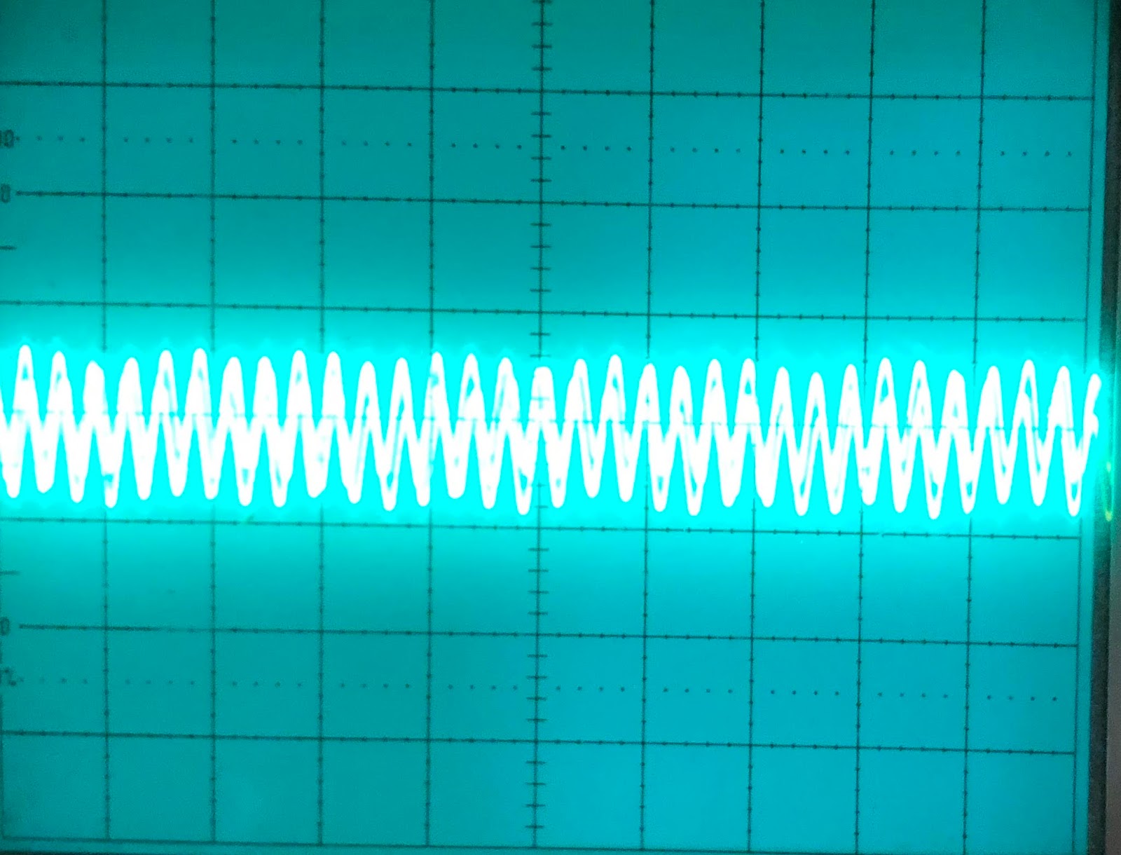
I spent the last few days breadboarding the moog filter, and got it mostly working yesterday. But cutoff did not work as expected. On the scope I could see that the wave amplitude got slightly smaller when turning the pot counter clockwise, but at the same time the centering of the wave dropped (adding a negative dc component) and the wave got distorted.
After a lot of debugging I switched what transistors in the CA3046 I used for the bottom pair of the ladder, the one with the common emitter. I had chosen not to use the internally connected pair because of the way I breadboarded the circuit.
This fixed things. Studying the datasheet for the CA3046 I discovered this:
Pin 13 is connected to the substrate, and should be connected to the most negative part of the circuit!
This means that the transistor between pins 12-13-14 CANNOT be used as a normal transistor after all. Switching it for 6-7-8 worked well. Instead, I tied 13 to -15V. I am using two more CA3046s on the breadboard and have to rewire them too to free up pin 13. I am having an issue where the DC component of the signal increases as the cutoff drops, not sure if that's related.
Anyway - I remembered that I have intended to use a different dual transistor for the Xonik VCO. Looking through my parts box tonight I found these:
BCM847BS
BCM857BS
They are matched dual transistors. They are however in tiny SOT-363 packages. For the 'production' version of the filter they pose no problem but they suck for prototyping. Still, they may be a good replacement for all transistors in the filter.
Update: They also come in SOT-666 and SOT-457/TSOP-6:
TSOP-6 seems a little easier to handle so perhaps I'll look for that instead.
To get a feel of how my filter is performing, I took a closer look at the Moog Little Phatty, and how its output looks on the scope.
Waveforms
The LP does not have discrete selectable waveforms. Instead, it has a continously changeable waveform that starts as a triangle wave, goes through saw and sqare and then ends up as a pulse wave.
This is what it looks like when turning:
Here are the four variations that most closely resembles the four mentioned waveforms:
Pulse wave. Notice how it is no longer centered around 0V - instead, the TOP is at 0V.
There are two things to notice:
First of all, the wave is not straight, it curves slightly. The triangle wave is actually on its way to becoming a sine wave, and the saw wave is almost like a half sine with an abrupt but not instant fall to the bottom. These photos are taken at a rather high frequency, but the effect becomes even more pronounced as the frequency drops. This means that the perceived level of the triangle wave is significantly lower than that of the other waveforms, just like with a sine wave. It also probably introduces different overtones than the waveforms from a 'cleaner' waveshaper does, which may greatly affect the character of the synth. Interesting!
Second, the wave is not always centered around 0V. This is something I've wondered a lot about after looking at various service manuals - a lot of them use a capacitor to center the wave, which means that waves with uneven energy levels above and below 0V would end up not being sentered. This is clearly the case with the LP - look at the photo of the pulse wave above, it has its TOP at 0V. This is fine and inaudible as long as the output does not start clipping, and mixing multiple oscillators that are not synced would probably reduce the offset. Still, it's interesting to see that this is actually done in professional instruments. I worked hard on my waveshaper to prevent this, perhaps it's unnecessary.
Resonance and self oscillation amplitude
Here is a video of what happens when I turn on resonance with the cutoff set to max. I then gradually reduce the cutoff to introduce self oscillation:
As you can see, the amplitude is quickly reduced to less than 50%. Then, when adding self oscillation, the self oscillation has an amplitude closer to (but less than) the original signal. It never overpowers the original:
Original wave, no resonance
Full resonance and filter fully open
Cutoff turned down, filter is self oscillating
Resonance pot response
In my last post I explained how I found that the resonance CV for the juno filter definitely not was exponential, but not sure if reverse exponential (using a reverse log pot) or linear was the best. Here is how the LP responds:
All pics are taken with the cutoff slightly higher than middle. Self resonance becomes visible about when the pot pointing to the right. This is independent of cutoff, and is fairly similar to the linear pot in my Juno VCF circuit.
Oscillator mixing
The little phatty has two oscillators. I would expect mixing them to simply sum them up, but it seems the total is less than the sum. I did the summing by running two similar waveforms on both oscillators and synching oscillator 1 and 2. The sum reached it's peak with oscillator 1 at 100% and oscillator 2 at 50%, after this further summing only changed the shape of the output slightly. It seems to me that the synth does some soft clipping or similar, which becomes more apparent when using overload.
Overload
Overload increases the amplitude of the signal. At first it appeared that it only doubled the amplitude:
But when lowering the cutoff and then turning on overload, we see that the wave is heavily distorted:
Switching to a different waveform shows this even more. It seems that the actual amplification is much more than doubled, but that the Little Phatty uses something like a compander/limiter circuit to soft clip the output (or maybe not - it starts stretching long before the edges reach the peak) - see how the middle of the wave is much more amplified than the top/bottom: