Tuesday, February 14, 2023

Filter CV range calculations

Update: I've used 17.9mV throughout this post as the V/oct input to the exponential converter. Not sure where I got this number from, but in my posts on temperature compensation I use 17.5mV per octave at 20C. The change in range per degree is approximately 60uV. This places 17.9V 0.4mV or 400/60 = 6.67 degrees up, at 26.67C. I've recalculated things and it doesn't really change anything except for the tracking so I've left this post as is. 

Now here's the fun part of the last post :-) 

I did a quick measurement of the input CV to the exponential converter.

For an output of 150nA we need an input of 72mV

For an output of 1.16mA we need an input of -149mV


This means we have a total range 231mV. With the expected 17.9mV/octave this covers 12.9 octaves. If we want to cover 14 octaves, we need 17.9 mV * 14 = 250.6mV.

It looks like 14 oct may be hard to achieve in practice, as < 150nA will give an output that always attenuates, and one additional octave when we're at 1.16mA would need 2.32mV which is much more than the max we're able to generate. But for the sake of this discussion, let's go for a 14V range, starting at 72mV.

We then want to add +/-3 octaves of tuneability, to cover temperature changes and parts differences. Normally, these 3 octaves will be useless, but being able to change the input voltage by a similar amount will give a voltage at the expo converter that is +/- 3*17.9mV.

To cover this, the range seen at the expo converter should have a range of 17.9mV * 20 = 358mV. It should start at 72mv - 3 * 17.9mV = 125.7mV and go down to -232.3mV

We know that the maximum output of the CV summer is around +/-10V with +/-12V rails. That means that if we set -10V out of the CV summer to end up as -232.3mV, we need an 1/43 attenuator.

Selecting a nice and round number for the attenuator, 1/40, we would need -9.25V in to reach -232.3mV

That would put the top voltage at 5.03V, giving a range of 5.03V - -9.25V = 14.28V

ok, so that is the MOST we can do. But let's pick a number that is easier to work with. Let's restrict the output of the CV summer to a range of 10V. Having a 0-5V CV input (that should cover 20 octaves) means we can use a -2x gain, that's pretty neat.

So, with a 10V range in, and a 358mV range out of the voltage divider before the expo converter, we need a 10V/0.358V = 27.93 attenuation. We already have a 560Ohm tempco at the bottom of the divider. Picking a 15kOhm resistor at the top will give us a 27.78 attenuation, that's pretty close - it gives 360mV out for 10V in.

Applying this to the original output values gives us:

Needed input top: 125.7mV * 27.78 = 3.49V

Needed input bottom: -232.3mV * 27.78 = -6.45V


So - we need a circuit that produces a 0 to -10V output from a 0-5V input, and then offsets that output by 3.49V

We already know that the first part is achieved by a -2x gain. Using a 100k feedback resistor we could use a 50k input to achieve that.

For the 3.49V we connect a resistor to -12V. The gain has to be 3.49 / -12 = -0.2908. With a 100k feedback resistor we thus require a 344k resistor. 

The nearest standard value is 330k or 360k if using a more fine grained scale. Using a 360k resistor will give a gain of 100 / 360 = 0.278 and an output of 3.33V. A 330k resistor gives a gain of 100/330 = 0.303 and an output of 3.64V. Let's go for the 360k first, just because -3.33(3333)V is such a nice number. The range at the input is now 3.33333V to -6.666V (mmmmm!).

Converting back to the output at the expo converter, we get 3.33/27.78 = 120mV and -6.66/27.78 = -240mV. 

If we instead go for the 330k resistor, it would set the range at 3.64 / 27.78 = 131mV to -6.36 / 27.78 = -228.9mV

Now, none of these cover the entire range we originally wanted. The 360k resistor is 5.7mV away from reaching the lowest point, the 330k resistor is 3.4mV away from the highest point. The worst offset is thus about 0.31 octave away from our intended range. As we have 3 octaves to work with in both directions, I'd say both options will work.

Backtracking a bit more, we get that our new range, 360mV (for the 360k resistor, or 359.9 for the 330k resistor), covers 360mV/17.9mV = 20.11 octaves. That's fairly accurate without any kind of tuning, which is a very good starting point!

To sum it up:

Use a 50k resistor between CV input and the negative op amp terminal

Use a 100k feedback resistor

Use a 330k resistor between -12V and the negative op amp terminal

Use a 15k resistor on top of the voltage divider (connected to the op amp output)

Use a 560R resistor to ground at the bottom of the divider

NB: 15V/-15V supply is really 12V/-12V, I just couldn't be bothered changing the labels.

Update:

When using 17.5mV the range is instead 124.5mV to -229.5mV. 20 octaves would be 350mV. Using a 0-10V input to the resistor divider would give perfect tracking for a 28.57 attenuation, which would require a 15.44k resistor on top.

If we keep the 15k resistor we will get 0.486V/octave instead of 0.5 at the input. It doesn't matter too much as we have a lot of tuning range, though we COULD combine a 15k and a 470Ohm resistor if we wanted to.

Now it's time to test this. Quick Batman, to the LTSpice-mobile!

(We have one last issue to tackle though, temperature compensation. But let's not spoil the fun yet!)


Edit: testing

Red: CV input, Blue: CV summer output, Green: I_abc

My calculations are correct. I see a 3.64V to -6.36V output after the CV (With a 330k offset resistor). 

The voltage at the expo converter is 130.87mV down to -161.3mV, after that it flattens out meaning we've reached the limit of the converter at its 25C state (we needed it to reac -149mV for a 1.16mA current so that's ok). This happens when CV is 4.44V btw.

I_abc is 15nA to 1.28mA.

Light blue: expo converter base voltage, Green: I_abc

We do see a bit of non-linearity when the expo converter base voltage reaches around -122mV (CV is around 3.6V). Not sure what is going on there, I saw the same thing with the unchanged circuit. It would mean that the last octave (-122mV to 149.9mV) is not tracking properly, though this either should not be a problem because it is so high anyway, or we have a bit of room to calibrate it out. 

Frequency response

I did some fairly manual frequency response measurements, plotting the filter response for various CVs and reading the -3dB cutoff frequency. It's not entirely accurate but gives a good indication:

CV: Frequency

0.75V: 3.48Hz (oct 0, but never gets above -2.2dB)

1.00V: 8.6Hz (oct 1)

1.25V: 17.9Hz (oct 2)

1.50V: 36Hz (oct 3) "Baseline" for expectations later

1.75V: 74.33Hz (oct 4)

2.00V: 150Hz (oct 5)

2.25V: 304Hz (oct 6)

2.50V: 606Hz (oct 7)

2.75V: 1.21kHz (oct 8)

3.00V: 2.34kHz (oct 9)

3.25V: 4.47kHz (oct 10)

3.50V: 8.20kHz (oct 11, expected 9.2kHz)

3.75V: 14.1kHz (oct 12, expected 18.4kHz)

4.00V: 22.34kHz (oct 13, expected 36.8kHz)

4.25V: 32.8kHz (oct 14, expected 73.7kHz)

4.50V: 41.9kHz (additional octave, highest reachable cutoff)

As we can see, tracking is quite accurate from between oct 1 and 2 up to between octave 10 and 11. We will be able to tune in 40kHz as well, with an additional 0.5V CV (=2 octaves) left for temperature compensation etc, meaning we can get a workable 4Hz to 40kHz.

PS: Since it looks like the most compensation is needed at the top range, we could perhaps go for the 360k shifting resistor option instead, it will shift everything up by about 2/3 octave and allow more calibration on top.


Temperature compensation

We're using a 560Ohm tempco. Let's see what PPM rating it should ideally have. Now, tempco values are usually defined with a 0% change at 25 degrees. At 25 degrees, we would expect the expo converter to need 17.5mV + 5 * 0.06mV = 17.8mV per octave. Let's calculate the necessary input voltage:

V_in * 560 / (15000+560) = 0.0178V, V_in = 0.494V

Now, if the temperature rises by 10 degrees, we would need 17.8mV + 10 * 0.06mV = 18.4mV for the same change. To keep the CV input equal, we see that

0.494 * x / (15000 + x) = 0.0184V

x = 580.32Ohm. In other words, the resistance needs to change by 20Ohm or 0.5Ohm per degree.

From my previos work I have that

560 * (1 + x * (10^-6)/10) = 580

x*10^-6 = 580/560 - 1

x = (580/560 - 1) / 10^-6 = 3571

Which should mean that the resistor should have a 3571ppm/C temperature coefficient.

The ones I have, Vishay Linear PTC, TFPT0805L5600FV (684-1021 from RS components), are nowhere near this. They are 4110+/-400 ppm/K, and a simple example says they are expected to be 560 * 1.042 = 583.52 at 35 degrees. The worst case scenario should be 1.046, = 585.76, let's round to 586. While this may not be good enough for a VCO, I think it has a fair chance of working for a VCF. Let's calculate.

The output of the voltage divider at 35 degrees should be near

0.494V * 586 / 15586 = 18.57mV, or 0.17mV off from what we expected.

At 35 degrees, a semitone is 18.4mV / 12  = 1.533mV. 0.17mV equals 11cents of error. Over a 14 octave range, the accumulated error will be 155 cents or 1.5 semitones. 

If instead the temperature rose by 25 degrees to 50C, the resistor should be at 1.110 * 560 = 622Ohm. The needed output would be 17.8mV + 0.06 * 25 = 19.3mV. The output from the divider would be 19.67 or 0.37mV off, equaling 24 cents, and over 14 octaves 338 cents, equaling 3.5 semitones.

Without temperature compensation

To get a better understanding of what we are up against, let's see what the offset looks like if we don't use a tempco.

Starting again at 25 degrees, we know that 0.494V in gives 17.8mV out.

But then, at 35 degrees, it STILL gives approximately 17.8mV out, while the exponential converter needs 18.4mV. We have a 0.6mV error instead of the 1mV we would get with the tempco.

Over 14 octaves that accumulates to 8.4mV or 5.5 semitones - or almost half an octave. This is for a 10V change. If the change is more drastic, say 25 degrees, the error will be 0.06 * 25 = 1.5mV/oct for a total of 21mV, or 1.14 octaves. As we have a +/-3 octave tuneability, this should also be within reach. We would, however, need to know the temperature!

Keeping multiple VCFs tracking

With a tempco in place, and assuming that it is somehow affected at least not too much differently than the internal temperature of the expo converter, and also assuming that the VCFs won't drift THAT much from each other in terms of temperature, say +/-5 degrees, we COULD see as little as 0.38 semitones difference (given all VCFs are tuned to the middle freq, we would see a +/-7 oct range to drift in). This would not be perceptible in terms of cutoff but perhaps for resonance. 

WITHOUT the tempco, we have different option - measuring temperature and keeping several lookup tables. Apparently, this is what some Sequential synths do their VCO calibration, making them playable without warmup. 

We would however need a temperature sensor close to the expo converter. It is an exciting thought and I should definitely explore it further, especially seeing as thermistors are hard to get, expensive (2-3USD per chip) and have to be manually soldered.

It may even be an idea to use a temperature sensor for tuning the filters even with the thermistor in place...

A thought about tuning

I started wondering about how to best tune the cutoff. We can send a sine-like wave and see how it is attenuated. This will work up to the maximul DCO frequency which is something like 20kHz, but above that, in the most troublesome territory, we have no built-in source (though we could possibly use a VCO, but they are themselves not completely stable).

But we DO have resonance. If the resonant frequency is directly and proportionately related to the cutoff frequency, could we measure the resonance wave (e.g. just frequency counting) instead?

Monday, February 13, 2023

Tuneable filter with 14 octave span

I intend to make the juno filter tuneable in software. To do this, I hoped to add a 20 octave range to the CV and just use that. But simulating the filter gave a few surprises:
- when using a 25k input resistor to get 20 oct range, the output of the initial op amp exceeds the rails, so it will clip.
- the maximum cutoff for the filter at the current implementation is around 48kHz
- Below 7-ish Hz the filter acts like a band pass filter so the input is always attenuated, meaning lower frequencies are not possible.

Now, the two last facts are not a big problem. They happen on the filter side of the exponential converter, which is not as temperature sensitive so range hopefully won't change that much with temperature.

The expo converter however will change a lot, meaning the input needed to get a certain output will not stay the same. THIS is where we need to apply tuning relative to temperature.

So what I need to look at is the circuit before the expo converter transistor pair. I need to make sure that THAT can go above and below what is needed for control at 25 degrees celcius. To do this I've started out mapping out what currents into the filter core gives what cutoff. Here is a short table:

2mA = 47.2kHz
1.5mA = 45kHz
1.2mA = 43.5kHz
1.1mA = 42.5kHz
1.0mA = 41.5kHz
0.8mA = 38.6kHz
0.7mA = 36.5kHz
0.6mA = 34.2kHz
0.5mA = 31.3kHz
0.4mA = 27.3kHz
0.3mA = 22.5kHz
0.2mA = 16.3kHz
0.1mA = 8.7kHz
50uA = 4.4kHz
25uA = 2.23kHz
12.5uA = 1.11kHz
6.25uA = 553Hz
3.125uA = 274Hz
1.56uA = 136Hz
781nA = 67.4Hz
390nA = 33Hz
195nA = 16Hz
97.7nA = 7.64Hz
48.8nA= n/a, alltid under -3dB

So... from around 100nA and up to 0.2mA, the tracking seems to follow the rule of doubling the current = double the -3dB cutoff point. After that it falls off a bit. I think that a range of approx 4-40kHz is fine, that's about 13.5 octaves. 

That means that the input range we're looking for is about 100nA to 1.2mA. Next up will be looking at the circuit as it is and see what the input to the expo converter is at these currents. Then I'll see if I can change how the circuit works to allow the input to go lower and higher than this. At a stable 25degrees this won't have any impact (it simply won't work), but it will allow us to correct for changes later. Maybe.

A bit more testing

I did some more measuring and calculations today. First of all, I calculated the necessary resistor to get 1V/oct response. The Juno uses a resistor voltage divider with a 560Ohm tempco at the bottom. To get 1V in = 17.9mV out (17.9mV is the magic number for expo converters at 25C), the top resistor needs to be 31.745k to get perfect tracking. In the current design this is achieved by a 20k multiturn pot combined with a 10k and 8k2 resistor. 

In the 12V version of the filter, we have a few issues.

Without any changes, Iabc tops out at 1.07mA. We need at least 1.16mA to reach 40kHz.
Allowing a 20V input (or rather, changing to a 25k input to get 20 octaves from 5V input) will not work as the cv input opamp output will hit the low power rail (-12v) before going all the way.

So, what can be done:

1) By switching the 10k input resistors on the LM13700 Iabc inputs for 8.2k ones, we get a max Iabc of 1.3mA

2) By decreasing the top resistor in the resistor divider, we can get a response that is lower than 1V oct, for example 0.8V/oct. This means that the range output by the cv input summer can be within the power rails. 

I did some inital trials without calculating too much. For easier reading I use a 0-20V CV input with a 100k input resistor. Swapping R34 with a 5k (reducing the top resistor by 5k) and replacing 10k Iabc resistors with 8.2k, I get a CV AFTER the summer that goes from 6 to -10V (at 15.6V input). The Iabc response goes from 25nA at 0V to 1.3mA at 14V. 150nA, which we know from earlier is about the lowest we need, is output at 2V input. 

20V CV input and around 0.8V/oct tracking. +/-12V filter

Red: CV input, Green: Voltage after summer, shows saturation at around 16V CV. Blue: I_abc, tops out when CV is around 14V.


This means that our useable range is around 12V, from 2V to 14V, and that we have around 2V above and below this. We already have a fairly useable tuning range.

So, what should I do next?

Given 20V in and 100k input res (will be changed to 5V/25k)

1) Find the range we need for 14 octaves (150nA to whatever)
2) Find a gain + resistor divider that puts 3 V in at 150nA and 17V in at whatever is needed for 14 octaves up.
3) Input summer must not saturate, eg. stay within +/-10V output for the full range.

This will be fun!

BUUUT. What about the tempco resistor? Will it still adjust itself correctly when the top resistor is no longer the same? Well, that needs to be checked. 

And for later: At what input audio does the filter start to distort?

EDIT: Input to expo conv: 72mV in = 150nA out, -159mV in = 1.16mA out

Thursday, February 9, 2023

Distortion 1.3 (?)

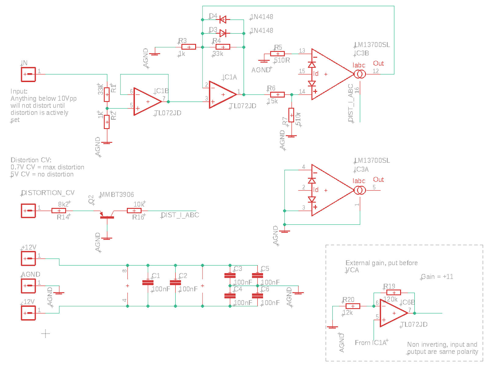
So after all the distortion testing, I've landed on a very simplified circuit:


This one only does soft clipping, but with a very reduced parts count compared to the soft/hard one.
It has no VCA and no switching, and CV control is simplified (which means that the upper 0.7V of the CV is not effective due to the voltage drop across the transistor, but it saves an op amp.

I had hoped that I could connect the output of IC1A directly to the VCA through a < 4.7k resistor, to make the VCA into a gain stage, but that introduced too much non-linearity into the equation. We need to use the non-inverting amplifier in the lower right corner, but it can be placed externally to save space on the distortion board. If we choose to have it on the board we should also reintroduce the CV circuit from the previous distortion to make cv 0-5V again.

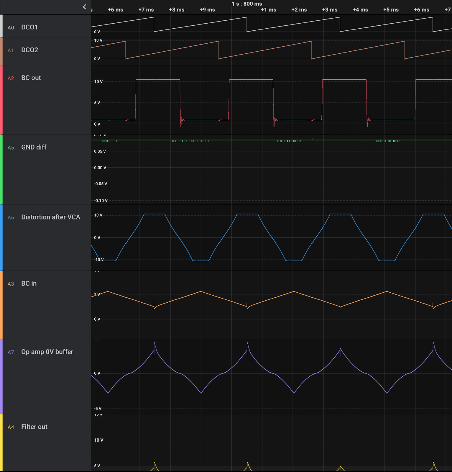
Bottom: Output of VCA shows that the almost linear triangle input has been distorted. This is when connecting the output of IC1A directly to the VCA through a 3k3 resistor.

When using an op amp gain stage in between, most of the non-linearity is gone. What is left is introduced by the distortion circuit, see the output above.


Sunday, February 5, 2023

Distortion again

After discovering that my hard clipping circuit introduced a lot of noise on the gnd line, I decided to put a 1k resistor before the clipping diodes. When doing soft clipping, this put the 1k inside the feedback loop, but this didn't seem to matter too much.

However, now the soft and hard clipping modes are very similar, to the point that I wonder if it is really necessary to have a hard clipping mode at all.

Soft clipping, four diodes and 1k in feedback


Hard clipping, two diodes


Hard clipping, four diodes

Now, it's very hard to tell the difference with a sine input, so perhaps I should redo this with a more discrete function to see how it actually performs. But more importantly, I should try this out in practice.

Soft saw(ish)


Hard saw(ish), two diodes

Soft triangle


Hard triangle, two diodes

Soft triangle, two diodes

If the conclusion is that hard and soft clipping is too similar, I may also look at ways of improving the soft clipping to keep amplitudes more the same without having to compensate in the output VCA.

Update:
TWO diodes soft clipping is much less similar, perhaps that's the reasonable option - only two diodes for clipping

Here is a +/-5v with matching soft and hard clipping - without any amplitude compensation:

The output ends up at around 7v in both cases, which is pretty cool. We COULD trim it down to 5v again but we could also just leave it.

Now, there is ONE problem with all of this - the input will only distort if less than +/-5v. Once we start summing oscillators stuff we'll get distortion from the get go. Not sure exactly how to handle this as we want to be able to get distortion from a single osc too, so perhaps this is better solved in dry/wet mixing? If not, we need to attenuate the input further or use an input gain vca which i REALLY don't want to do, especially if we have an output VCA as well (we do already have two output VCAs so it may be solved in software though).

Update 2:
I did a change of the circuit to use a 68k/1k resistor divider instead of a 33k/1k, and to compensate for this I put a 240k feedback resistor in place of the 120k at the output gain stage to keep unity gain.

Now 10V is allowed through the circuit undistorted. When I send +/-5v through, distortion starts at around 50% turn of the CV pot. For +/-10V it starts at around 25%. 

With the output gain at max distortion set to get a +/-10V distorted output for a 10V input, I get a +/-8V output for a soft clipped 5V, so a significant gain. For hard clipping it is even more, the clipping level is around +/-9v for 5v input (though the slope is likely not as steep.

Again, I need to try this in practice to see what feels best.

+/-5V input with max soft clipping

+/-10V input with max soft clipping

+/-5V input with max hard clipping

+/-10V input with max hard clipping

In practice the big difference is that with the 10v pass option we may actually end up clipping against the +/-112v rails if we don't carefully adjust the gain through the cycle.

With the 5v pass option, we clip much sooner, and the max output is much lower. It can never reach 10V even if the input is 10V.

All in all it DOES look like the 5v version performs fairly well. Without any gain correction - and the gain CV set to about 3.3V, we do get a bit of gain for the 5V input as distortion increases. For 10v there is a bit of distortion from the start, more for hard than soft clipping.

Soft clipping, 5v in, no distortion

Soft clipping, 5v in, max distortion

Soft clipping, 10v in, no distortion set gives a bit of distortion on output

Soft clipping, 10v in, max distortion gives a higher output than for 5v max distortion.


Hard clipping, 5v max distortion

Hard clipping, 10v max distortion, not much higher than for 5v

Hard clipping, 10v no distortion. Distorts from the start, and more than for soft clipping


Modified circuit with unity gain at max vca cv (or without cvm just a buffer).


High frequency filtering in audio output

One thing that I've put off for a long time is selecting filter caps for various op amp output drivers. 

Today I had a look at some datasheets to figure out what others are doing. 

Generally, it seems that filtering (by putting a cap in parallell with the feedback resistor in an inverting op amp) is only done at the last stage of the circuit, not within the circuit itself. It seems that very little filtering is done except for biasing using electrolytics in the audio path to center the signal. I assume the final filtering is just to stop radio frequencies, stuff that we don't want to escape the circuit perhaps?

Here is what I found

Self on audio (book) page 237: 100pF/4k7 = 339kHz

Self on audio (book) page 359: 27pF/10k = 589kHz

JP8 source mix: 10p/100k = 159kHz

JP8 VCA cont 15p/100k = 106kHz

Juno 6 out: 47p/3k3 = 1.02MHz - See juno 60 where the 3k3 is actually crossed out in the schematics and 27k written instead.

Juno 60 out: 47p/27k = 125kHz

Juno 106 out: 22p/33k = 219kHz - Interestingly enough, and supporting of my theory that filtering only happens at the last stage, the 106 has the same feedback resistor as the Juno 6 (3k3) right after the filter, but no cap, as it has a mixer at a later stage too, mixing in High-pass filter.

JX-3P out: 330p/10k = 48kHz

JX-8P synth mix: 100p/47k = 33.8kHz

JX-8P chorus: 100p/22k = 72kHz

THAT4301 reference: 47p/20k = 169kHz

Sooo, I can't say that the findings are exactly conclusive. Before starting this research I suspected that the cutoff would at very least be above 22kHz (being the upper limit of human hearing) and perhaps at least the double as we want to make sure to not remove anything wanted. Most of these results seem to support that, with roland ranging from 33kHz up to 219kHz (disregarding the Juno 6 which seems to be too high). I'd say somewhere between 100 and 150kHz is probably a nice compromise.

Now, I started looking at this to find a good cap for my distortion circuit, which has an output feedback resistor of 120k. Playing around with various caps and looking at the output of the scope, it seemed like 10p would give a result where frequencies up to 22kHz did not get much attenuated. Calculating the cutoff using 120k/10p gives 133kHz which incidentally fits nicely between 100k and 150k.

That said, as the distortion is in the middle of the circuit, I may as well skip filtering alltogether.

Friday, February 3, 2023

Tanh - a nice S-curve function

I was just made aware by a colleague that tanh makes for a nice ease-in/ease-out/S-curve function!

Here is a quick example that takes a normalised value x (0-1) and gives a nice curved version out. In this case, map is a function that moves the input from one range [0, 1] to another [-1, 1]

function easeInOutCool(steepness, x) {
  const mappedX = map(x, 0, 1, -1, 1);
  return (1 + Math.tanh(steepness * mappedX)) / 2;
}

Wednesday, February 1, 2023

DAC and ground in multicard systems

Now this has been a big mystery to me for a long time.

DACs tend to have two ground pins - digital and analog ground. It's not an insane thought to think that these should be connected to different ground planes. 

Reading up on this previously, the mantra has been that you could do this, but then the two ground planes should be connected under the DAC.

While this may be fine for a single DAC system, where the DAC is the only point where analog and digital meet up, my system is definitely nothing like this. I have multiple DACs on a single card, and multiple cards in the system. 

Connecting two DACs this way, with the grounds connected under both DACs, would (at least in my mind) create a ground loop which is not desireable. So what should a poor designer do?

Today I found this document: 

https://www.analog.com/media/en/training-seminars/tutorials/MT-031.pdf

"Grounding Data Converters and Solving the Mystery of "AGND" and "DGND" (MT-031)

It describes in detail how to approach this, including the multi-card issue. A short short summary is:

- AGND and DGND _pins_ should both be connected to AGND at the package
- If V_digital is not the same voltage as V_analog, V_digital should be decoupled to AGND
- AGND and DGND planes should be connected at each card through Schottky diodes to prevent a potential difference buildup

There are a lot of other considerations and preconditions that have to be met, but this at least provides some good guidelines and explanations.

Ferrite beads

One advice still troubles me a bit though. Using ferrite beads. They seem like the magical solution. The problem however, is that every DIY'er out there treat them like they are all created equal. I did read about this earlier and it seems this is not at all true - you have to know a lot more about your circuit and pick the correct bead. Without this, you just waste money and board space. 

I'll see if I can find more about this later.

Hard clipping problems

When testing the distortion circuit in the full FX module, I noticed that the bitcrusher output was affected by the distortion. Once the clipping started, I could see a similar small change in the bitcrusher.

After a lot of debugging, I've concluded that this is due to noise on the GND line. It looks like we're sinking enough current into the GND or something, to make it shift by more than +/-100mV


Green is GND at the distortion module in relation to GND at the Teensy. Red is bitcrusher output

The noise was even visible as far back as the waveshaper. 

I have tested a lot of stuff to see f I could fix it: caps in the signal path, bypass caps, buffered GND by using an op amp to get a separate 0V reference - that didn't work at all:

Purple is 0V at the op amp output, it is NOT a constant 0v...

I then tried inserting a 4.7uF cap and a 1k resistor in the path, after the main gain cell but before the hard clipping diodes. It removed most of the noise, we're left with about +/-5mV. However, the clipping is much more rounded and the max output is reduced from +/-6v to +/- 3.6 approx. I then realised that the 4.7uF cap isn't necessary.

I tried reducing the resistor, first to 560Ohm (+/- 12.5mV noise) and then 220hm (+/-28mV noise). It looks promising.

I now introduced the same 1k resistor in the soft clipping circuit (R8):

It is part of the feedback loop but it didn't really look like it affected the performance of the soft clipping. Not sure what is going on exactly.

I then tried using 4 instead of 2 diodes for hard clipping. This increased the output to +/-7.6V, but it isn't as hard clipped as before. I assume that I could compensate for this in the feedback amp but for now it is running at max.

Comparing the soft and hard clipping shows that they are quite similar, perhaps too similar:

Hard clipping with 560Ohm res and 2 diodes

Soft clipping with 1k res in feedback - the top and bottom is not as flat as the hard clipping

My next step is to simulate the new circuit. There are a few things to worry about such as the hard vs soft clipping, and more importantly that the 1k resistor feeds into a 12k and a 15k respectively, the division of current at this point is very dependent of the exact value of the resistors. 

Things to test: What happens if I tap the signal to the feedback amp BEFORE the 1k resistor? how exactly is the soft clipping affected by the 1k in its feedback? How different are the modes?

I am not extremely happy about this design, but maybe it is enough to save hard mode. The unpleasant truth is that without changes it simply cannot be used. 


Monday, January 30, 2023

Changing center and range of a signal

I needed to change a +/-12V input to 0-3.3V. This calculator has the solution in the form of a differential op amp calculator:

https://masteringelectronicsdesign.com/differential-amplifier-calculator-2/

PS: You may have to use a negative reference voltage.

Tuesday, January 10, 2023

DCO Calibration issue

After fixing the issues with calibration related to the compiler bug, I hoped everything would go smoothly. Unfortunately that was not the case.

After calibration, when running through frequencies, I would sometime see a kind of discontinuity, where the wave amplitude would drop to zero and then build back up to the correct height again over two periods. 

I looked at the DAC charging voltage and could see a kind of asymptotic behaviour where the charge voltage suddenly rose much faster than it should, and when it reached max, dropping back to zero but still rising with the same speed. Clearly the DAC output overflowed.

DAC Voltage error. The first little drop is only due to missing calibration. The asymptotic looking one is where the interpolation overflows and voltage drops to 0.


It took some testing to figure out what was going on: For a single sample in the calibration, the dac voltage was detected significantly lower than it should, and more importantly, lower than the previous sample. This meant that the slope multiplier should have been negative. But the slope multiplier is unsigned, so it overflowed and ended up with a large positive number instead.

Then, when interpolating between the two values, we would add a large number instead of subtracting, leading to the spike (and DAC overflow) we saw.

But why did we get the wrong value during calibration?

It happens during the first cycle of a single note calibration. For some reason, we detect that the wave amplitude is too high - higher than the comparator voltage - when in reality it is not. This leads to the binary search continuing in the wrong half of the voltage range and the calibrated voltage ends up being around 32768 instead of what it should have been.

DAC voltage calibration - 7th cycle starts off too low and never reaches back up to the correct voltage.


Debugging the issue is a pain in the ass, because we are dependent of the wave being reset at exactly the same point every time. If something changes, the voltage may not cross the comparator voltage, and while it seems we have fixed the error, it still might be there.

I strongly suspect that what happens is that the voltage reaches the comparator voltage AFTER we have changed the dac and timer to a new frequency, but before the interrupt handler resets the wave. My fix was to move clearing of the comparator flag into the interrupt routine, so we are guaranteed that a comparator interrupt stems from the current cycle, NOT anything before it. It looks like it works but who knows...

I also saw another strange thing - some of the cycles are of different lengths than they should be, by as much as +2us. But then, often the next cycle or the one after that is a bit shorter. I have not been able to properly explain what is going on. I suspected that the comparator interrupt may have been part of it, that it triggering would make the program enter the interrupt routine before the timer interrupt, and then staying there for long enough to delay the timer interrupt, but I have not been able to confirm this. My fix was to disable comparator interrupts once we get it once during the calibration period, to prevent the code from reentering the interrupt routine due to the comparator interrupt being high. When this was NOT done, we would probably enter the interrupt routine repeatedly until the timer interrupt fired and disabled the comparator.

Now everything seems to work properly and I've started working on a verify routine, one that runs through frequencies where I suspect the charge voltage may be too high (such as in the middle of interpolation) and checking if we hit the comparator voltage during normal operation.

Low range sweep after calibration

High range sweep after calibration


I do however suspect that that is not the case. Had the timer been exponential between two key points and the voltage linear we would see an error, but both are linearly interpolated meaning the voltage should match the frequency fairly well. 

We have another error too - a strange falloff at the end. The charging voltage is too low even if the DAC has not maxed out. The consequence is rather low as this is in the > 20kHz range but I still want to figure out what is going on.


Saturday, December 31, 2022

This year's x-mas gift from Mikroelektronika: A compiler bug

I have spent the last month chasing down an extremely strange bug. When I added a new global variable to my DCO, calibration stopped working.

I first spent a long time trying to figure out what was going on, and after a couple of weeks I ended up posting a rather vague description to the MikroC forums. 

What I was seeing was very weird - I had a double loop, and the inner loop ran fine the first time around but the second time the inner loop ran it skipped the first part. The outer loop was never re-executed but sometimes the program continued in the mail function afterwards.

I did a lot of testing but the results were always similar, some code was skipped and sometimes everything crashed. It felt like the program pointer moved to a different address. I started suspecting some kind of memory leak.

After the post in the forums I was asked to provide a minimal example - I normally do this anyway but this time I had a hard time doing so, as everytime I changed the program it started working.

Finally, I resorted to placing all variables and functions at absolute positions, as I suspected that some kind of memory collision was the problem. It took a looong time to get this right, and it wasn't always possible, but at last I managed to get a fully absolute-position program that still bugged in a similar way.

Now I gradually stipped the program down, re-running the code for every small change to make sure it still had the bug and that it could be brought back to working by moving something. I placed empty variables at absolute positions to prevent other, used variables from moving around, and also made sure that the empty spacers were not called upon anywhere in the code that was executed BEFORE the spot where the bug showed up.

This took me every spare moment from the 17th of December and the 13 days. Finally, yesterday, I had a minimal program with only a single function call inside the loop. Removing a single spacer variable made a single library variable (FLASH_write.savedINTCON) move too, and the program would start working. 

I was totally exhaused and posted a new question to the forums.

As I waited for answers, I used a diff tool to see if the two generated asm outputs from the working and non-working programs were different. They were not. I then did the same for the machine code listing file (.lst). Now I could see a single changed line! In the non-working version, a single instruction - MOVLB 0 - was missing. I took a screenshot and prepared to write a follow-up question.

When I logged in to the forum again, the user Janni had just posted an answer - and that was the exact same thing that I found. Janni confirmed that this was actually the error, the instruction changes RAM banks and when it is missing the function returns to the wrong part of the program, exactly what I was seeing.

Adding 'asm movlb 0;' after the call to FLASH_write fixes everything.

So here we are - it turned out to be a compiler bug after all. I am completely drained but incredibly happy that the error was found as I can't have any errors in the DCO.

Unfortunately, it seems Mikroelektronika stopped developing the MikroC compiler in 2019 so it is unlikely that the bug will ever be fixed. At least now I know what to look for if this ever happens again!

Happy new year everybody!

MikroC: Absolute positioning

I've spent the last weeks debugging a strange problem in MikroC, and to do that I had to absolute position every function and variable to make sure the program did not change in RAM and ROM.

Here is how to do that:

Global and local variables

Add absolute 0xXXXX to place at address 0xXXXX. If you have an initialiser it must be placed BEFORE the absolute. E.g.:

    unsigned short a absolute 0x0123;

    unsigned short a = 1 absolute 0x0123;

    unsigned short a[32] absolute 0x0123;

Variables need to be used somewhere to prevent the compiler from removing them. Also, the compiled code is different if the assignment is done on a separate line vs if it is done inline, which changes the size of functions.

For global variables they may be used in main simply by assigning to them. For arrays it's enough to assign something to the first position. E.g.:

    a = 1;

    a[0] = 1;

Function parameters

I have not been able to place these at absolute addresses

Internal library variables and function parameters

I have not been able to place these at absolute addresses

Functions

These are postfixed with org 0xXXXX:

    void myFunc() org 0x0123 { ... }

You may also put the address after an extern declaration in an h file:

    extern void myFunc() org 0x0123;

Library functions

These may also be positioned, just skip the function body:

    void libraryFunction() org 0x0123;

Collisions

Variable collisions are common, in cases where the compiler has decided that they won't conflict. In those cases, it is not possible to absolute only one of the colliding variables, as the compiler won't place anything else on an address occupied by an absolute'd variable.

That means that you have to set all variables to absolute for that particular address - and if one of them is a function parameter you're out of luck it seems as those cannot be absolutely placed (or at least I don't know how)

Sunday, November 6, 2022

Wavemixing and loudness

When designing the continuous wavemixer, I thought a bit about the fact that as you turn the dial, the (perceived) loudness of the output changes. As the number of harmonics in the signal changes, from none with the sine wave, to “all” in the square wave, the output sounds progressively louder even if the signal amplitude is the same.

This is most pronounced when going from sine to saw, but triangle to saw also has a noticeable difference, so I’ve contemplated changing the input mix to compensate for this. As the cross fade is computer controlled, I could also compensate in the source mix vca, which is good since it can be done after the hardware has been made.


When studying “off the shelf” VCO chips with built-in waveshapers, I noticed that the different wave outputs indeed have different amplitudes. I have not been sure if this is just a byproduct of how the waves are generated in hardware, or actually a design feature.


Today I read the data sheet for the AS3394 (a CEM3394 clone) because I was curious about building a simpler synth voice, and noticed that it has a built in waveform mixer/selector. And in the text, it is clearly stated that the waveforms have different amplitudes to keep the loudness the same. Saw is 27% larger than triangle, and square is 27% larger than square. 


Unfortunately, I cannot see the same numbers in the waveform plots on page 4, but it shows that triangle output is 50mV, saw is 45mV and square is 30mV. Now, 27% larger than 30 is 38, and 27% larger than 38 is 48.4, so we are very close to the real value for square, but saw does not make sense. However, the saw output on pin 9 is stated as 45mV as well, so this could just be a copy/paste error. The 27% text is lifted straight from the CEM data sheet which does not have a similar plot so it’s hard to tell if the original text is wrong or if the plot is wrong without measuring. I have bought an AS3394 so maybe I’ll get around to checking it sometime.


CEM3340


Tri: 0-5v

Saw: 0-10v

Square: 0-12v


Meaning square is 20% larger than saw, but saw is 100 larger than tri. Also, they are not centred, meaning they should be centred using a capacitor (or with separate centring circuitry - caps mess with pulses, they won’t be centred around 0. Not uncommon in real designs though, and something that will happen in the filter anyways, one just need to take it into account when mixing several sources to prevent clipping).


SSI2130


All outputs are 0-2.5V, though pulse goes slightly below 0 (-34mV)


For more on the waves, see:


Tri:


https://en.m.wikipedia.org/wiki/Triangle_wave


Saw:


https://en.m.wikipedia.org/wiki/Sawtooth_wave


Square:


wikipedia.orghttps://en.m.wikipedia.org › wikiSquare wave - Wikipedia

Saturday, July 30, 2022

XM8 as a vocoder

I have thought about the posibility of using the XM8 as a vocoder for a long time, but had decided to not go ahead with it due to the added complexity.

However, while designing the voice cards I realised that by just adding tiny modifications, I could at least leave the door open to adding a vocoder daughterboard later. Let me explain.

Vocoder architecture

A vocoder has some central components. First of all, it takes two inputs:

 - one (usually a voice) that is analysed for frequency content by dividing the input into frequency bands using bandpass filters. The amplitude of each band is captured using an envelope follower.

- another one (usually an instrument sound rich in harmonics) which is divided into the same frequency bands as the first one, and where the amplitude is controlled by the amplitude of the first input.

The effect is that the second input "mimics" the first, making the instrument "talk".

In addition to the inputs, a noise source is used, and amplitude is sampled (analog sample and hold) at intervals set by a variable clock.

Here is the block schematics of the classic ETI Vocoder DIY kit:


It has three main parts - analysis and synthesis at the top, and sound generation at the bottom. The two oscillators are used in place of the second input.

How to implement this in the XM8

Now, we would need to implement the whole analysis, sample and hold and voiced/unvoiced detection on the daughterboard. The output from the board would be 16 CVs that can control VCAs. 

The second input will be either 
- External audio - if we want to use a different source for our "instrument"
- Output from the low pass filter on voice card 1 - that way we can use everything on the voice card except the state variable filter as a mono synth. 

We would then feed the second input as External input to all voice cards. By sending the input directly to the SVF - this is already part of the architecture - we can use the SVF in place of the second block of band pass filters in the schema above. The cutoff frequency for each filter is fixed and can be calibrated (part of the existing design) digitally. As an added bonus, the cutoff frequency may be moved to change the voice pitch (or even invert or reorder the bands).

There are two additional important things in the ETI vocoder design:
 - the first and last frequency bands are made using low pass and high pass filtering respectively. Fortunately, this is supported by the SVF.
- every second band is phase inverted. This is also supported by our architecture.

Changes needed to the voice cards

- Add a CV input going to the SVF. 
- Add an output from the low pass filter (pre VCA), this will be used on the first voice card to use as the second input.

Changes needed to the main/input board

- Add a switch between external input and voice card 1 LPF output (this is a good idea anyway)
- Add a switch between this input and a third input used for vocoder noise source. This would be controlled by the voiced/unvoiced detector on the vocoder analysis board.
- CV outputs going to the vocoder board to control voice input volume etc.
- Chaining between synths - either we need a separate analysis board on synth two or we need 8 VCA inputs. We need a separate Ext audio out, tapped after ext audio mux, to send voice card 1/noise to second synth.

A four channel mux may be used, if we let the vocoder analysis board control A1 and input noise to input 3 and 4, the mainboard may control A0 to switch between external input and voice card 1 LPF. A1 would then effectively override the two inputs (and should have a pulldown resistor so that it is disabled if no vocoder daughterboard is fitted.


Usage: LPF filter VCA must be turned down on all voices, and Ext in turned up and connected to SVF for all. Voice card 1 may be used as input to the other sources.

As one XM8 probably ends up having only 8 voices, we need to chain two to get a full 16 band vocoder. Here is one way of doing that:

We need to have a single analysis board to be able to detect voiced/unvoiced properly. Bus chaining requires level matching between the synths, so ext bus input should probably have VCAs.

Things to test

I am unsure of the steepness of the bandpass in the ETI vocoder. The SVF has a 12dB bandpass.

Update: According to the Deliyannis bpf docs, one filter has 12dB cutoff, so two must have 24dB. That means that we may have to run the audio through both the LPF and the SVF (as HPF).

Deliyannis band pass filter

While reading about the human voice filter bank in the VP-330 (on the Oakleysound site) i realised that the ETI bandpass filter is called a Deliyannis bandpass filter or resonator, a calculator can be found here: 

https://www.changpuak.ch/electronics/Deliyannis_Bandpass.php

http://earmark.net/gesr/opamp/bpf.htm