Sunday, February 3, 2019

Moog Little Phatty - oscillator and filter, how does the output look

To get a feel of how my filter is performing, I took a closer look at the Moog Little Phatty, and how its output looks on the scope.

Waveforms

The LP does not have discrete selectable waveforms. Instead, it has a continously changeable waveform that starts as a triangle wave, goes through saw and sqare and then ends up as a pulse wave.

This is what it looks like when turning:


Here are the four variations that most closely resembles the four mentioned waveforms:


Pulse wave. Notice how it is no longer centered around 0V - instead, the TOP is at 0V.
There are two things to notice:

First of all, the wave is not straight, it curves slightly. The triangle wave is actually on its way to becoming a sine wave, and the saw wave is almost like a half sine with an abrupt but not instant fall to the bottom. These photos are taken at a rather high frequency, but the effect becomes even more pronounced as the frequency drops. This means that the perceived level of the triangle wave is significantly lower than that of the other waveforms, just like with a sine wave. It also probably introduces different overtones than the waveforms from a 'cleaner' waveshaper does, which may greatly affect the character of the synth. Interesting!

Second, the wave is not always centered around 0V. This is something I've wondered a lot about after looking at various service manuals - a lot of them use a capacitor to center the wave, which means that waves with uneven energy levels above and below 0V would end up not being sentered. This is clearly the case with the LP - look at the photo of the pulse wave above, it has its TOP at 0V. This is fine and inaudible as long as the output does not start clipping, and mixing multiple oscillators that are not synced would probably reduce the offset. Still, it's interesting to see that this is actually done in professional instruments. I worked hard on my waveshaper to prevent this, perhaps it's unnecessary.

Resonance and self oscillation amplitude

Here is a video of what happens when I turn on resonance with the cutoff set to max. I then gradually reduce the cutoff to introduce self oscillation:


As you can see, the amplitude is quickly reduced to less than 50%. Then, when adding self oscillation, the self oscillation has an amplitude closer to (but less than) the original signal. It never overpowers the original:

Original wave, no resonance

Full resonance and filter fully open

Cutoff turned down, filter is self oscillating
Resonance pot response

In my last post I explained how I found that the resonance CV for the juno filter definitely not was exponential, but not sure if reverse exponential (using a reverse log pot) or linear was the best. Here is how the LP responds:


All pics are taken with the cutoff slightly higher than middle. Self resonance becomes visible about when the pot pointing to the right. This is independent of cutoff, and is fairly similar to the linear pot in my Juno VCF circuit.


Oscillator mixing

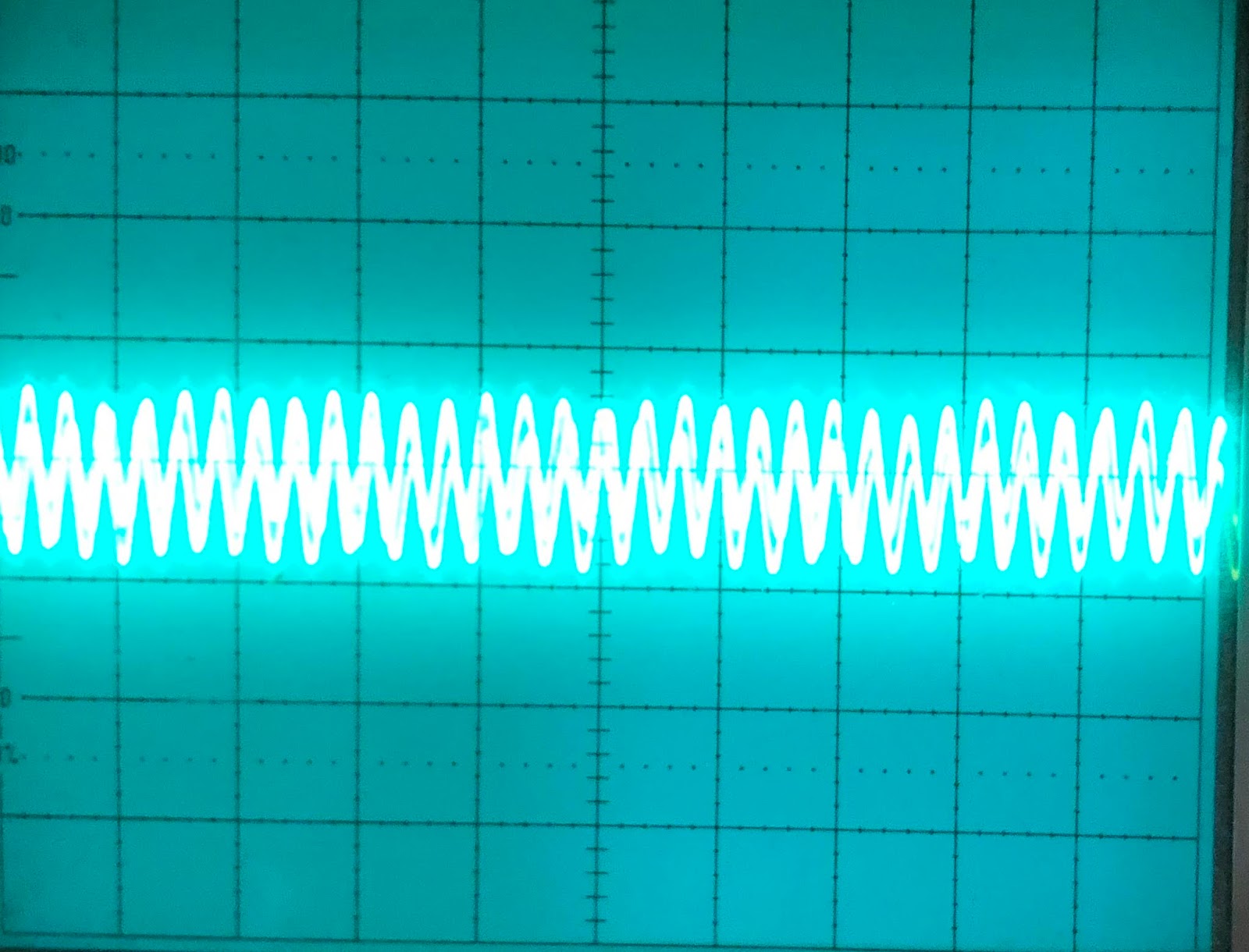
The little phatty has two oscillators. I would expect mixing them to simply sum them up, but it seems the total is less than the sum. I did the summing by running two similar waveforms on both oscillators and synching oscillator 1 and 2. The sum reached it's peak with oscillator 1 at 100% and oscillator 2 at 50%, after this further summing only changed the shape of the output slightly. It seems to me that the synth does some soft clipping or similar, which becomes more apparent when using overload.


Overload

Overload increases the amplitude of the signal. At first it appeared that it only doubled the amplitude:


But when lowering the cutoff and then turning on overload, we see that the wave is heavily distorted:


Switching to a different waveform shows this even more. It seems that the actual amplification is much more than doubled, but that the Little Phatty uses something like a compander/limiter circuit to soft clip the output (or maybe not - it starts stretching long before the edges reach the peak) - see how the middle of the wave is much more amplified than the top/bottom:


Overloading a triangle wave:


Overloading a saw wave:


Saturday, February 2, 2019

Juno filter IRL testing

After all this simulation it's time to start testing the circuit in real life.

I breadboarded everything, and it works great right off the bat.

CV

As I am not doing computer control at the moment, and I had no log pots around, I decided to go for the emulated log pots from Elliott and others. They work great! I did a log pot for the VCA CV.

Resonance

Resonance works great as well, and the filter has no problem self oscillating.

As for the resonance CV, it became apparent that its CV should NOT be exponential. It should either be linear or we should use a reverse log pot like in the minimoog - which one depends on how much movement you want in the beginning vs end. With a linear CV it takes quite some time before anything audible happens, and it's a bit hard to control the self oscillation once it starts. With the reverse log self oscillation starts a bit early but is easier to control. Fortunately making a simulated reverse log is as easy as a simulated log.

There are a few things to be aware of with the resonance when it self oscillates. The amplitude of the oscillation is related to the signal AFTER our input summer. If we apply a weak signal at the input and try to compensate by increasing the amplification in the output VCA, we will also increase the amplitude of the self oscillation, meaning it quickly overpowers the input signal in volume. Here id an example:

First we use a 100k resistor. We adjust so that our output is half that of the input signal, and by doubling the scale on the oscilloscope we get a overlapping waveform.


Then we add resonance and start self oscillation.


Now we replace the 100k input with a 200k input. To get a similar output amplitude we now have to turn the VCA CV fully right.

Input is attenuated to 50% by doubling input resistor

Unity gain is recovered by turning up VCA CV


 But look at what this does to the self oscillation - it is now much higher than the previous one.


Input resistor

I tried hooking the input up to the output from my macbook to process audio. I had to replace the input 100k resistor with a 10k one to get an ok output volume. But processing the input audio was great fun.

Overdrive

I decreased the input resistor and increased the feedback resistor even more to try to overdrive the filter. This did not work very well. I started getting hard clipping and if the input was high enough, something latched up and I had to cycle power.

Later I tried feeding the output back to the input summer instead, using a 20k linear pot as a voltage divider and an inverting opamp (because I have not swapped the inputs on the output OTA, the output is not in phase with the input). This proved so much nicer. I got a controllable overdrive that did a much softer clipping. It did also latch up stuff when the feedback was too high, but a great experiment all in all. I still have to look closely at the signal levels of the original signal to decide a proper range for the overdrive feedback. Oh, and of course the output level gets much higher, this has to be compensated elsewhere. Maybe its possible to tap the signal before the output VCA and do something to decrease the VCA gain CV when the overdrive CV increases. Or this could be done in software.

Monday, January 28, 2019

Jupiter 6 filter schematics cleanup

I've cleaned up the schematics a bit. This is the version with linear vca and resonance CVs, 10 modes, overdrive and possibly oscillation issues. It may change in the future.


Jupiter 6 All pass filter

This post

https://www.muffwiggler.com/forum/viewtopic.php?t=137105&start=all&postdays=0&postorder=asc&sid=3ef1fe17aeeff7d7fd87444b7188ac69

mentions that by mixing the input with 2 x the BP filter, you'll get an all pass filter. The same does this pdf:

https://www.analog.com/media/en/training-seminars/tutorials/MT-223.pdf


I tried this with some success. I had to disconnect the 33k resonance resistor, but after this I got a response with a slight 667 mdB notch.


I will try breadboarding this later.
The MT-223-pdf also mentions an alternative way of doing a notch filter:


Which gives this notch:


As opposed to the notch we get by mixing LP and HP:

Sunday, January 27, 2019

OTA filter cell

Fun fact - after looking for an explanation for the OTA used in the juno for a couple of years, I found it in my bookshelf because someone mentioned a circuit in the Musical Applications for Microprocessors book by Hal Chamberlin.

When trying to understand a circuit, I often look for visually similar circuits, but even though I have found several OTA filters, they are always different from the Juno one. But here is the clue: These are similar:

The typical Roland filter cell to the left, its equivalent to the right.
The left one is what you find in the Roland schematics, the right one is found in papers and OTA filter explanations elsewhere. It is explained in some detail in the section on voltage controlled filters, page 201 and onwards in 'Musical Applications for Microprocessors'.

The cell is really quite simple - the resistors, 68k and 560Ohm function as voltage dividers to reduce the input signal to the OTA. This is true for both the 68k on the input and the 68k in the feedback loop.

Jupiter 6 filter - overdrive and multiple output variations

Overdrive

With a 3.9k input gain feedback resistor I could easily pass a 20V p.p. wave through the filter without distortion. But I wanted to see if I could get a distortion similar to the moog filter, and yes, I could.

Swapping the 3.9k resistor with a 33k makes the filter overdrive close to 10V p.p, quite similar to the Moog.

This is of course pre-filter amplification. I have seen people talking about the minimoog doing feedback of the original signal through the external input jack, and this sounding better, so I'll try that next. I also need to come up with a good way to control overdrive, one that is not so dependent on input amplitude.
Input (green) vs output (blue). 33k input resistor, 50k output pot


Output variations

This being a state variable filter means it can produce a multitude of filter variations at the same time - low pass, band pass, high pass and notch. It is also two filters after one another, which means we can get various falloff. I've played around with this and come up with 10 variations that are more or less usefull:

12dB LP
24dB LP
12dB HP
24dB HP
6dB BP + 12dB LP
6dB BP + 12dB HP
Notch (first SVF)
Notch + LP
Notch + HP
Notch + BP

I am not sure of the usefullness of all these but the cost to add them all is very little. Here is how I indend to wire them, with resistor values giving the following 'plateau' gain.


Constant current inputs

Just like with the Juno and Moog filters, I've swapped the resonance and vca gain CV circuits for my own, linear designs. The VCA gain  control is exactly the same as for the Juno (but with slightly different part values), and has a similar deadband. The resonance on the other hand, is different. The resonance circuit works opposite of the one in the Juno, increasing the resonance OTA gain reduces the amount of resonance.

Because of this, increasing CV must decrease the output current. Also, when doing exponential conversion in software later, we must generate a negative exponentially decaying signal instead of an exponentially increasing one, which is too bad as it means that we cannot have a common control system for all filters. I will have to look closer into this.

CV vs I_abc for one resonance OTA, original Jupiter 6 circuit. With a linear response, a similar CV curve must be calulated in software.


Oh, and because of the way I did the linear control, we don't get a deadband.

Jupiter 6 filter - oscillation issue

I did a lot more work on the Jupiter 6 filter today.

First of all, I tried figuring out why I get oscillation on the input whenever cutoff CV was above 4.7V.

I have yet to figure out what is going on, but I tried replacing all ideal opamps with TL072 simulations and I still have the issue. I will have to breadboard the circuit to see if it is real or not.

But even so, there are a few things that make this happen:

1) When resonance CV is at 0V, I get oscillation if cutoff CV > 4.7 and input gain feedback resistor > 3.9k. With 4.7V CV I could use at least a 15k resistor without problems.

2) Decreasing the 33k resistor from input to the resonance OTA, or removing the line completely, fixes the problem

3) Increasing resonance also removes the issue.

All in all, it seems that anything that makes MORE current pass through the circuit causes this oscillation. I tried quickly reading up on op amp oscillation but no quick remedy was found. I also cut down on the circuit to the point where only the first SVF with constant current controls (no expo converters etc) and no output VCA was left and still had the issue.

Thursday, January 24, 2019

State variable filters, some quick resources

I found these resources while trying to understand how resonance defeat works in a state variable filter:

A very good general description
https://www.electronics-tutorials.ws/filter/state-variable-filter.html

Some more about gain and stuff
Says that passband gain should not be affected by Q (resonance)
http://sound.whsites.net/articles/state-variable.htm

All pass and equations
https://www.analog.com/media/en/training-seminars/tutorials/MT-223.pdf

Musical Applications of Microprocessors
Then I found this on a forum (which I unfortunately forgot to bookmark):

I first read about how SVFs work in Hal Chamberlin's book, Musical Applications of Microprocessors , where there's a lovely diagram of the filter's structure. I later spotted that same diagram in an article about an analogue computer. Apparently an SVF and a physical model of a spring have the same structure! Well, they're both dynamic systems that resonate, so I shouldn't be too suprised if they share the same mathematics.

Incidently I have this in my bookshelf, so I checked it, and it did indeed have a good diagram. But even better - it had an implementation using CA3080, which is almost exactly identical to the one in the Jupiter 6!


It's the first time I have come across that implementation, it even says that the capacitor-to-ground between the OTA and the buffer equals the configuration with the capacitor in the feedback loop of an opamp that I have seen elsewhere. Oh - and the book is from 1980, three years before the JP6 came on the market.


This one has both BP and band reject/notch. Oh, and it is missing the resistor i talked about in a previous post and has no change in gain for frequencies below the resonance frequency.


Matrix 12
I also looked at the Matrix 12 filter. It is NOT a state variable filter, it is a multimode filter, which mixes the output from four poles in various gain/variations to get 15 different responses. This matches well with what MT-223 above says about mixing different gains.

Cem chip used in the Matrix 12, CEM3372

https://pdf1.alldatasheet.com/datasheet-pdf/view/95160/ETC/CEM3372.html

On bandwidth vs Q:

Jupiter 6 filter resonance gain

When I first simulated the jupiter filter, I had made a mistake. I forgot to connect a 33k resistor from the negative terminal of the resonance OTA and to the filter input. I didn't notice, and all my plots looked good. More than that - I actually could add resonance without the lower frequencies getting attenuated. Reading up on state variable filters today indicates that this is a feature of this filter topology (http://sound.whsites.net/articles/state-variable.htm)

When I corrected this error though, to my great surprise, lower frequencies got heavily attenuated once resonance went up!

I have checked and rechecked and traced the original JP6 PCB but I always come to the same conclusion - the resistor is there.

I even went back and simulated the filter with and without the resistor, looking at both filter response and phase, and honestly, I can't see ANY difference, except for the attenuation.

Zero resonance without resistor

Zero resonance with resistor


Max resonance without resistor, same low frequency gain as no resonance

Max resonance with resistor. gain has fallen by 24dB


This begs the question: What is the purpose of this resistor/line?

Right now my only two conclusions are either that it is there to attenuate lower frequencies on purpose - exactly the thing other filter designers fight to. Or LTspice simulates the circuit incorrectly.

I guess won't get an answer to the last question until I breadboard the circuit.

Update: Scott Bernardi made a comment about the attenutation here: http://www.bernacomp.com/elec/og2/og3_4pmultimode.html - Without it the resonance would start clipping (depending on the rest of the circuit of course). That makes sense.


Jupiter 6 filter resonance

I'm feeling fairly satisfied with the Juno and Moog filters now, so it's time to do another round with the JP6 filter.

The cutoff control is not that interesting, I assume I can tweak the starting point just the same way I did with the two others, and reuse the expo converter from the Juno - after all, the filter core should function the same way, with a doubling in control current resulting in a doubling of frequency.

The resonance on the other hand, is completely different. The juno returns the difference of the filter output and filter input, tapped at the last stage, and returns it to the start of the filter. The jp6 on the other hand, returns the SUM of the output of the first stage and the filter input and returns it to the start of the filter, where it is also mixed with the output of the second stage.

I discovered quite early on that reusing the resonance control from the Juno filter did not work as it should. In fact, I got resonance with a 0V input and the resonance fell when increasing the CV. At last 10V was needed for a 'normal' response without resonance.

I went back to the datasheet, and discovered that the resonance OTAs are actually IR3109s, which means that they have built in exponential converters. This makes a huge difference of course. I went on to duplicate the expo converter from the juno filter, after all it should be a close approximation of the one from the IR3109, and add the rest of the JP6 control circuit. I also re-read the datasheet and it seems the JP6 DAC outputs up to 10.7V (see page 4b, DAC amplitude). Finally, each resonance CV feeds two voices and each voice has two resonance OTAs (In fact, two voices share one IR3109), so I added two additional OTAs to the simulation to get a correct split for the I_abc.

So far so good. But the OTA CV circuit has a trimmer in it. And this trimmer has a huge effect on not only how high the resonance peak gets, but on how little resonance we get too.


In the Juno filter, fully turning off the resonance OTA meant no resonance. In the JP6 on the other hand, there is no absolute 'no resonance' point. The OTAs 'defeat' resonance by feeding back more of the output of the first stage (and third stage), so turning it off means maximum resonance.

Here are some plots. First of the resonance CV from 0 to 10.7V and the corresponding I_abc current for each OTA. We can clearly see that the lower the CV, the higher the current - and higher I_abc means a higher gain in the OTA. There are three plots, each for a resonance trimmer setting of 0, 0.5 and 1 (wiper position).
Wiper at 0

Wiper at 0.5

Wiper at 1
Second series of plots show the corresponding frequency response is. Note that for a trimmer setting of 1, A 0V CV still results in a quite visible resonance. Wiper at 0 or 0.5 shows no bump, but which one is the correct one? Or is it somewhere in between?

Wiper at 0

Wiper at 0.5

Wiper at 1

Finally, a plot of trimmer position vs minimum resonance. The top green line is wiper at 0. All lines after the grey one (wiper at 0.5) shows a bump so they are definitely not correct, but are any of the others?

My conclusion then, which I guess is ultimately quite fun, is that I have to understand what is going on. How does this filter create resonance, and what exactly is it that the OTA output defeats. When knowing that, I can go back and calculate what the best output of the OTA is, and get the necessary theoretical gain.

OBTW: Why bother? Why not use the circuit like it is? Well, for one I would not know how to properly calibrate it, and second, I think I still like to keep the resonance control linear and do the expo conversion in software, the way the other filters do.

UPDATE: I tried reading up on Q, resonance etc. It is not easily understood exactly how it comes about. But I DID find some great reasources on state variable filters, that inspired me to try adding more features - tapping bandpass after pole 1 and 3 (6dB) and creating notch / AP versions. Very exciting!

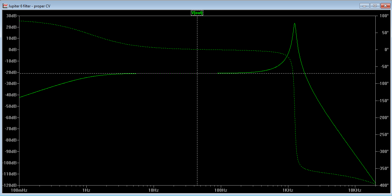
I ended up doing a quite crude comparison of the falloff between the Juno and Jupiter filters. I positioned a marker at resonance frequency and then measured the falloff from the 'plateau' down to it. I found the dropoff to be about 10.3dB and so I have adjusted the Jupiter filter to match this when the resonance CV is 0V by setting the resonance offset trimmer U23 to 0.25.

Juno filter 


Jupiter filter