Thursday, January 24, 2019

State variable filters, some quick resources

I found these resources while trying to understand how resonance defeat works in a state variable filter:

A very good general description
https://www.electronics-tutorials.ws/filter/state-variable-filter.html

Some more about gain and stuff
Says that passband gain should not be affected by Q (resonance)
http://sound.whsites.net/articles/state-variable.htm

All pass and equations
https://www.analog.com/media/en/training-seminars/tutorials/MT-223.pdf

Musical Applications of Microprocessors
Then I found this on a forum (which I unfortunately forgot to bookmark):

I first read about how SVFs work in Hal Chamberlin's book, Musical Applications of Microprocessors , where there's a lovely diagram of the filter's structure. I later spotted that same diagram in an article about an analogue computer. Apparently an SVF and a physical model of a spring have the same structure! Well, they're both dynamic systems that resonate, so I shouldn't be too suprised if they share the same mathematics.

Incidently I have this in my bookshelf, so I checked it, and it did indeed have a good diagram. But even better - it had an implementation using CA3080, which is almost exactly identical to the one in the Jupiter 6!


It's the first time I have come across that implementation, it even says that the capacitor-to-ground between the OTA and the buffer equals the configuration with the capacitor in the feedback loop of an opamp that I have seen elsewhere. Oh - and the book is from 1980, three years before the JP6 came on the market.


This one has both BP and band reject/notch. Oh, and it is missing the resistor i talked about in a previous post and has no change in gain for frequencies below the resonance frequency.


Matrix 12
I also looked at the Matrix 12 filter. It is NOT a state variable filter, it is a multimode filter, which mixes the output from four poles in various gain/variations to get 15 different responses. This matches well with what MT-223 above says about mixing different gains.

Cem chip used in the Matrix 12, CEM3372

https://pdf1.alldatasheet.com/datasheet-pdf/view/95160/ETC/CEM3372.html

On bandwidth vs Q:

Jupiter 6 filter resonance gain

When I first simulated the jupiter filter, I had made a mistake. I forgot to connect a 33k resistor from the negative terminal of the resonance OTA and to the filter input. I didn't notice, and all my plots looked good. More than that - I actually could add resonance without the lower frequencies getting attenuated. Reading up on state variable filters today indicates that this is a feature of this filter topology (http://sound.whsites.net/articles/state-variable.htm)

When I corrected this error though, to my great surprise, lower frequencies got heavily attenuated once resonance went up!

I have checked and rechecked and traced the original JP6 PCB but I always come to the same conclusion - the resistor is there.

I even went back and simulated the filter with and without the resistor, looking at both filter response and phase, and honestly, I can't see ANY difference, except for the attenuation.

Zero resonance without resistor

Zero resonance with resistor


Max resonance without resistor, same low frequency gain as no resonance

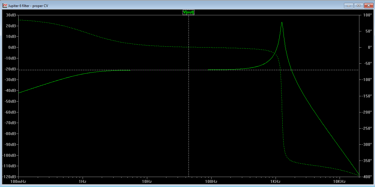
Max resonance with resistor. gain has fallen by 24dB


This begs the question: What is the purpose of this resistor/line?

Right now my only two conclusions are either that it is there to attenuate lower frequencies on purpose - exactly the thing other filter designers fight to. Or LTspice simulates the circuit incorrectly.

I guess won't get an answer to the last question until I breadboard the circuit.

Update: Scott Bernardi made a comment about the attenutation here: http://www.bernacomp.com/elec/og2/og3_4pmultimode.html - Without it the resonance would start clipping (depending on the rest of the circuit of course). That makes sense.


Jupiter 6 filter resonance

I'm feeling fairly satisfied with the Juno and Moog filters now, so it's time to do another round with the JP6 filter.

The cutoff control is not that interesting, I assume I can tweak the starting point just the same way I did with the two others, and reuse the expo converter from the Juno - after all, the filter core should function the same way, with a doubling in control current resulting in a doubling of frequency.

The resonance on the other hand, is completely different. The juno returns the difference of the filter output and filter input, tapped at the last stage, and returns it to the start of the filter. The jp6 on the other hand, returns the SUM of the output of the first stage and the filter input and returns it to the start of the filter, where it is also mixed with the output of the second stage.

I discovered quite early on that reusing the resonance control from the Juno filter did not work as it should. In fact, I got resonance with a 0V input and the resonance fell when increasing the CV. At last 10V was needed for a 'normal' response without resonance.

I went back to the datasheet, and discovered that the resonance OTAs are actually IR3109s, which means that they have built in exponential converters. This makes a huge difference of course. I went on to duplicate the expo converter from the juno filter, after all it should be a close approximation of the one from the IR3109, and add the rest of the JP6 control circuit. I also re-read the datasheet and it seems the JP6 DAC outputs up to 10.7V (see page 4b, DAC amplitude). Finally, each resonance CV feeds two voices and each voice has two resonance OTAs (In fact, two voices share one IR3109), so I added two additional OTAs to the simulation to get a correct split for the I_abc.

So far so good. But the OTA CV circuit has a trimmer in it. And this trimmer has a huge effect on not only how high the resonance peak gets, but on how little resonance we get too.


In the Juno filter, fully turning off the resonance OTA meant no resonance. In the JP6 on the other hand, there is no absolute 'no resonance' point. The OTAs 'defeat' resonance by feeding back more of the output of the first stage (and third stage), so turning it off means maximum resonance.

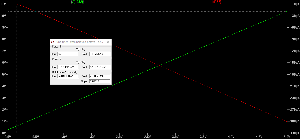
Here are some plots. First of the resonance CV from 0 to 10.7V and the corresponding I_abc current for each OTA. We can clearly see that the lower the CV, the higher the current - and higher I_abc means a higher gain in the OTA. There are three plots, each for a resonance trimmer setting of 0, 0.5 and 1 (wiper position).
Wiper at 0

Wiper at 0.5

Wiper at 1
Second series of plots show the corresponding frequency response is. Note that for a trimmer setting of 1, A 0V CV still results in a quite visible resonance. Wiper at 0 or 0.5 shows no bump, but which one is the correct one? Or is it somewhere in between?

Wiper at 0

Wiper at 0.5

Wiper at 1

Finally, a plot of trimmer position vs minimum resonance. The top green line is wiper at 0. All lines after the grey one (wiper at 0.5) shows a bump so they are definitely not correct, but are any of the others?

My conclusion then, which I guess is ultimately quite fun, is that I have to understand what is going on. How does this filter create resonance, and what exactly is it that the OTA output defeats. When knowing that, I can go back and calculate what the best output of the OTA is, and get the necessary theoretical gain.

OBTW: Why bother? Why not use the circuit like it is? Well, for one I would not know how to properly calibrate it, and second, I think I still like to keep the resonance control linear and do the expo conversion in software, the way the other filters do.

UPDATE: I tried reading up on Q, resonance etc. It is not easily understood exactly how it comes about. But I DID find some great reasources on state variable filters, that inspired me to try adding more features - tapping bandpass after pole 1 and 3 (6dB) and creating notch / AP versions. Very exciting!

I ended up doing a quite crude comparison of the falloff between the Juno and Jupiter filters. I positioned a marker at resonance frequency and then measured the falloff from the 'plateau' down to it. I found the dropoff to be about 10.3dB and so I have adjusted the Jupiter filter to match this when the resonance CV is 0V by setting the resonance offset trimmer U23 to 0.25.

Juno filter 


Jupiter filter

Monday, January 21, 2019

Juno and moog filter simulations for ltspice

I've uploaded the latest filter simulations:

Juno filter https://xonik.github.io/xm8/filters/juno/Xonik XM8 OTA filter.asc
Moog ladder filter https://xonik.github.io/xm8/filters/moog/Xonik XM8 ladder filter.asc

LM13700 OTA: https://xonik.github.io/xm8/filters/juno/LM13700.asy
Potentiometer: https://xonik.github.io/xm8/filters/juno/potentiometer_standard.asy

Moog ladder filter revised

After all the work I did on improving the range and controls of the Juno filter, I decided to have a closer look at the Moog filter. I have improved the following:

  • VCA CV is now similar to the Juno - it has an adjustable deadband at the start and a summing point for multiple CVs
  • Resonance CV is similar to the Juno in the same way
  • Cutoff CV summer has been altered to give a 10Hz cutoff from a 0V CV, with +/- 5.6 octaves trimability, fairly similar to the Juno.
  • I have added a tempco resistor to the exponential converter.
  • I have added an option to tap the audio output at 12dB/oct instead of 24. Resonance is still tapped at 24dB to get a nice high resonance. No switch has been drawn but either an electronic or mechanical DPDT switch will do.
  • I replaced the output buffer with a transinductance circuit and instead flipped the inputs to the VCA OTA to keep phase. This fixed the maximum cutoff frequency similarly to the Juno.
  • I added a linear FM input to the cutoff frequency.


In addition to all this, I've completely changed the signal attenuation/gain to enable overdriving.

Overdrive 

The Memorymoog schematics indicates that a 40mV p.p. at the transistor base of the bottom ladder transistor is the 'norm'. My simulations show severe distortion at this level. I could see distortion all the way down to 10mV p.p. I have suggested three component values that will work for 5, 10 and 20V p.p. input (with a 15mV p.p. base voltage at those values). This gives a slight distortion at the highest inputs, and further distortion should the input exceed the specification. For example, a 10V p.p wave maxes out at about 16V p.p even with much higher input.

How the overdrive sounds in practice is still unknown.

Input (blue) vs output (green), input is 8V to 30V p.p


Computer calibration

It would probably be possible to tune most parameters of the filter using lookup tables in the computer control. Here are some thoughts on that:

- If no deadband is needed (i.e. 0V input to the VCA CV gives an 'off' output), the U17 trim pot and R41 may removed. Keeping R41 but connecting it to -15, and changing the value to 1.5MOhm will give a 100mV deadband.

- The U13 VCA gain potentiometer can be replaced with a fixed resistor that gives a more-than-unity gain at max CV. By doing this, the VCA CV can be calculated in software to give a correct curve with a end point that results in unity gain.

- Similarly, U20 can be chosen in such way that it results in a resonance higher than what is wanted, and CV then corrected in software for max resonance.

- I would probably still keep the tracking potentiometer, but R36 can be replaced with a lower value, giving a lower frequency as a starting point. Then you could replace R32 with a 25k resistor to get 20 octaves of CV control, enabling proper calibration of lowest and highest cutoff.

- It IS also possible to replace the tracking pot U9 and resistor R23 with a 100k resistor. Tracking could then be adjusted in software.


Tuesday, January 15, 2019

Juno filter: cap values and expo converter musings

After spending the last few weeks experimenting with the Juno filter, I have some thoughts. It seems the exact compnent values along the signal path are not terribly important to how the filter works. A lot of the filter is tweakable as we've seen in my previous posts - the input CV ranges, the VCA gain etc.

I have tried various cap values as well, and today I made a comparison of both cap values and changes to the expo converter.

Expo converter

The expo converter core is dependent on a reference current. Right now that is set up using a 1.5MOhm resistor, but changing this does not change the output curve, it only changes WHAT linear CV gives what output.

I tried swapping for a 1MOhm resistor, and using the base octave trimmer I could still get the necessary output range. Here are the currents through a single I_abc resistor:

Using 1.5MOhm resistor, the output current is:

Full trim and 5V CV range: 3.2nA to 1.377mA
Center trimmed: 165nA to 168uA

Using 1MOhm resistor, the output current is:

Full trim and 5V CV range: 4.9nA to 1.379mA
Center trimmed: 248nA to 238uA

The center trimmed range is well within the total range independent of resistor, with room to spare for additional octaves.

Filter caps

The Juno 106 uses 240pF caps, other Roland synths use 330pF, and we use 270pF. Here are the responses to a center trimmed CV using a 1.5MOhm reference resistor:

240pF
0V = 7.7Hz
5V = 6.4kHz
10V = 42kHz

270pF: 
0V = 7Hz
5V = 5.7kHz
10V = 39kHz

330pF
0V = 6.1kHz
5V = 4.7kHz
10V = 34kHz

Note that at 10V all of the outputs are at their max (I_abc is 1.38mA) so tracking is off. But all filters reach well above 20kHz. If one aims for a 40k cutoff 240pF and 270pF seem equally suited.


Juno filter: VCA and Resonance CV circuit tweaking

I took a closer look at the Juno 106 circuit for VCA and Resonance CV to figure out what they did to the base-emitter voltage drop in the transistors in the circuit. While simulating it turned out that it actually uses a 10V resonance CV where I put 5V. This confirms my initial testing where I had to use 10V resonance CV to get a proper response.

Juno 106 VCA CV


Anyway, following the tuning instructions in the Juno 106 results in a response where the first 150mV of the CV does not output any I_abc current, because the transistor does not switch on until it sees a high enough voltage. This is practical as it will fully turn off the VCA. In my Xonik VCA I have assumed that 0V CV cuts off the output current, but if there are small differences in the supply lines or something we may still get a tiny output. The Juno does not have this problem because of the 'deadband'.

CV vs I_abc  (red) before calibration - notice deadband at the start of I_abc


CV vs I_abc after calibration, deadband ends at about 150mV

CV vs voltage at opamp output - notice that we get 10V at the start.

After calibrating the trimming I tested the current outputs:

VCA:
max -301uA

Resonance:
max -205 to -356 uA depending on the trimmer.

I wanted to add a mixing point for the VCA CV. I am not quite sure how to do this on the existing design - I could possibly add a resistor to the positive input of the VCA CV op amp - so I decided to use the current converter from the Xonik VCA.


Using standard component values, I ended up with this version


which has the following params:

VCA: 
max -320uA

Resonance:
max -147 to -405

If trimming the size of the deadband is not necessary, the trimmer and 1MEG resistor may be replaced with a 1.5MEG resistor to -15V. This will give a deadband of about 150mV.

Leaving out the 1MEG resistor will give 0 current at 0V but with the possibility of a tiny current leakage, slightly turning on the VCA.

Frequency CV

I also modified the Frequency CV mixer a bit, now the trimmer lets you add or subtract up to 5.6 octaves.

As a side note, the 390k resistor to -15V adds 3.8V to the output. Switching the resistor from the trimmer from 270k to for example 150k would give the same trimability and remove the need for the 390k, but makes the trimmer slightly more sensitive.


Here is the updated circuit. I still want to add linear FM of the filter cutoff, but other than this I am getting close to a version that can be tested.

Sunday, January 13, 2019

Juno filter with higher possible cutoff

While trying to find a suitable 0-5V CV filter range I discovered that my design had some unfortunate limitations.

The maximum cutoff achievable was around 16kHz. I tracked this down to two factors: The 220k resistor from the VCA-OTA output to ground and the output filter capacitor (fixed low pass filter). Removing the output cap helped a lot, but I still could not get higher than 30kHz cutoff independent of control current.

Cutoff is max 30kHz and has very poor tracking at high frequencies. Current is the total current for all four OTAs, divide by 4 to get I_abc

I still had to change the resistor, which meant I could not get proper unity amplification at 5V CV. Compensating elsewhere in the circuit (input buffer or pre-OTA) distorted the signal at my wanted 10V p.p. amplitude (while such a distortion may be desireable, I want control over it and it was not something I planned now).

I switched back to the original design with a 47k output resistor. Then I thought, I can compensate for the loss using additional output amps. I added two inverting amps (to keep the output in phase) and this worked well.

From my previous experiments I knew that I could replace the resistor-to-ground feeding a buffer, into an inverting amp with the same resistor in the feedback loop. Doing this meant I would only need a single additional opamp to get phase correction and unity gain. But doing his also had a surprising effect - distortion and cutoff was immediately improved!

Using this and a constant current input to the OTAs let me run the filter up to at least 130kHz. This is completely unrealistic though, as it would require a higher control current I_abc for the OTAs than they can handle (max is 2mA), but past 60kHz could be achievable

Max cutoff is above 130kHz (though this would break the OTAs) and tracking is near perfect.


Increasing range

I then re-added the expo converter and got a surprise/reminder. I still couldn't push the filter past 24kHz. I simply could not get a control current higher than about 760uA. After trying a few adjustments in the exponential converter itself (changing reference current and emitter resistor) I turned to my exponential converter simulator and quickly discovered the problem - the current is controlled by changing the voltage drop across the resistor connected to the OTAs control pin. The pin is always around -13.3V in the simulator, and the transistor pulls its collector further and further away from this to generate a higher and higher current. But at about one diode drop above 0V it cannot go any further, it simply cuts off.

Plotting the voltage at the right collector of circuit A shows that it cuts off above at approx 0.63mV. 
Similarly, the plot of the current running through the 18k resistor shows that it cuts off at about 860uA. Note that this is slightly higher than the 760uA of the OTA control because the voltage difference is higher (-15.6V here vs -13.9 in the OTA control)

So, to get a higher current than this, I had to reduce the resistor value (remember, U=R*I, to get a higher I from the same U, R must decrease).

Doing this let me generate up to 1.38mA, putting the cutoff close to 40kHz.

Changing to a 10k resistor increases the maximum current.

Tracking using the expo converter

CV response (0.5V/octave) using expo converter. Blue line has 18k resistor to OTAs, red has 10k and no output filter cap, and has slightly better tracking. Also note that the response is the same even if the resistor value changed, the base frequency has not moved up/down.


Note that I have NOT tried to tune tracking when using the expo converter, it is possible that one could get a lot better tracking than this by adjusting U15. It is however also possible that there is something that prevents the expo converter from getting a perfect tracking over the full frequency range.

Output lowpass filter

I've added a 22pF output filter cap in, which seems to give a cutoff around 50kHz. This affects the tracking at high frequencies a bit too, so I'll have to do some testing.

New circuit


Final notes

I do not know if changing the max cutoff frequency or the output lowpass filter affects the sound. It is possible that this messes with the Juno sound. Maybe the cutoff should not go as high (though the manual says 5-50kHz or 4-40kHz). I like try it at least. One could also squeeze out an even higher cutoff by reducing the resistor even further. The OTA control pin is at -13.3V in the simulator but it could perhaps be even lower in the circuit, but never less than the negative supply (-15V). The transistor never gets past about 0.7V. This means the overall range will be below 16V. As maximum I_abc is 2mA we COULD use an 9.1kOhm resistor and get max I_abc 1.75mA (or an 8.2kOhm and get 1.95mA, but then we are really close to the

Wednesday, January 2, 2019

Breadboarding the Juno filter

Such a nice morning, checking my wirings before powering on the juno filter prototype for the first time.

Tuesday, January 1, 2019

A closer look at the responses of the jp6 filter after fixing CV and bug

To make a good state variable filter with 12/24dB HP, LP and 12dB BP I simulated the JP6 filter and tapped it at various places to look at the responses.

For my simulated circuit, setting cutoff CV to 1.35 to get results comparable to my previous erroneous circuit. Resonance CV control is still a bit wonky but now it uses an expo converter. I have set reso to 0.5V (but there is a missing current limiting resistor in the circuit) to get 13dB resonance.

24dB LP:
- Cutoff: 500Hz
- Resonance: 13dB at 1.24kHz

24dB HP:
- Cutoff 3.2kHz
- Resonance: 13.2dB at 1.4kHz

12dB LP + 12dB HP,
12dB HP + 12 dB LP
- LP cutoff: 2.6kHz
- HP cutoff: 694Hz
- Center: 1.33kHz
- 13.4dB attenuation on top
- Resonance: Top has 1.1dB amplification

12dB LP with connection to second stage
- Cutoff: 772Hz
- Base attenuation 1.44dB
- Resonance: Top has 6.6dB amplification over base at 1.25kHz, base is -13dB

12dB LP without connection to second stage
- Cutoff: 769Hz
- Base amplification 1.4dB
- Resonance: Top has 6.6dB amplification over base at 1.25Hz, base is -10dB

12dB HP with connection to second stage
- Cutoff: 2.1kHz
- Base attenuation 1.7dB
- Resonance: Top has 6.4dB amplification over base at 1.4kHz, base is -13dB

12dB HP without connection to second stage
- Cutoff: 2.1kHz
- Base amplification 1.1dB
- Resonance: Top has 6.65dB amplification over base at 1.4kHz, base is -10dB


BTW: I have found another serious issue. The cap on the output amp prevents the filter from getting a higher LP cutoff than 14k. removing it gives a cutoff of about 20kHz at most. This does not seem right compared to the promised 5-50kHz in the datasheet.

Monday, December 31, 2018

Juno/jupiter VCA and resonance CV

I just discovered something surprising.

First of all, my Juno CV runs the output VCA at very low currents, less than 0.2mA, while the LM13700 can be driven up to 2mA.

I have started researching this to see if I can change the CV to get unity gain at 5V on the JP6. For some reason I expected the control circuit to be converting a linear CV to an exponential one, because I didn't think the Juno had it in it to do this elsewhere. But it makes perfect sense I guess, this lets us generate both linear and exponential envelopes in software.

I took a closer look at the juno 106 schematics and discovered that the CV present at R37 in my schema is not 0-5V. It is actually an adjustable voltage, amplified right after the DAC. It is adjustable from min 0.2V/max 10.3V to min 0.32V/max 10.42V.

Now, this means that the max current at the control of the VCA is about 0.3mA, It is not a major change but it is something at least. And without having to worry about changing the response curve of the VCA CV control, I can change the max control current easily.

As for VCA gain adjustment, I can either chose to add a slightly higher than unity gain and adjust this in software, or add a adjustment pot. A CV summing point may be a good idea anyway

PS: Without adjustment, CV below 0.6V will give 0V out due to the diode drop of the transistor.

A closer look at responses for the Jupiter 6 filter

NB: This post was written before i discovered a missing 33k feedback resistor. Results are not correct

To make a good state variable filter with 12/24dB HP, LP and 12dB BP I simulated the JP6 filter and tapped it at various places to look at the responses.

For my simulated circuit, setting cutoff CV to 0.2V (this has nothing to do with 1V/oct CV btw, look at the circuit to see exactly how it is wired) and Resonance CV to 10V (=off, see this post for details), gives the following results:

24dB LP:
- Cutoff: 507Hz
- Resonance (3V CV): 14dB at 953Hz

24dB HP:
- Cutoff 2kHz
- Resonance (3V CV): 13.7dB at 1.05kHz

12dB HP + 12 dB LP
- LP cutoff: 1.77kHz
- HP cutoff: 574Hz
- Center: 1kHz
- 10dB attenuation on top
- Resonance (3V CV): Top has 13dB amplification

12dB LP + 12dB HP
- LP cutoff: 1.77kHz
- HP cutoff: 574Hz
- Center: 1kHz
- 10dB attenuation on top
- Resonance (3V CV): Top has 13.5dB amplification

12dB LP with connection to second stage
- Cutoff: 666Hz
- Base attenuation 1.35dB
- Resonance (3V CV): Top has 6dB amplification over base at 885Hz, base is -1.26dB

12dB LP without connection to second stage
- Cutoff: 666Hz
- Base amplification 1.6dB
- Resonance (3V CV): Top has 7dB amplification over base at 885Hz, base is 1.6dB

12dB LP with connection to second stage
- Cutoff: 1.38kHz
- Base attenuation 1.2dB
- Resonance (3V CV): Top has 6dB amplification over base at 1kHz, base is -1.18dB

12dB HP without connection to second stage
- Cutoff: 1.4kHz
- Base amplification 1.7dB
- Resonance (3V CV): Top has 7dB amplification over base at 1kHz, base is 1.7dB


Sunday, December 30, 2018

Moog style ladder filter for the XM8

I have simulated a ladder filter for the XM8. It is based on various designs found around the net - I've studied the original moog circuit, the Schmitzbits one, the Yusynth one, the modified ASM-1 for emphasis voltage control and not least the Memorymoog (which is probably the source for the ASM-1) for the output VCA.

Cutoff CV is 1V/octave, using a 100k resistor to the mixing point at the negative terminal of U10. The point labeled cv in the schematics has a 0.5V/octave response, to allow 10 octaves of control using 5V CV.

U9 tunes tracking, it should be approx 18mV (17.5 - 18.2mV, depending on temperature) for a 1 octave increase.

U4 sets initial frequency (freq when CV is 0). Adjust to whatever you like.

U11 sets output symmetry.

I have suggested two alternatives for R16 and R24 - choose the one with the range you need for the input voltage. the 10Vp.p alternative will probably distort for higher amplitudes while the 20Vp.p is probably more noisy as it attenuates and amplifies more to run the core at the same amplitude.

Simulated circuit

Juno filter for the XM8

UPDATE: This filter circuit has some limitations to its maximum cutoff frequency and high frequency tracking. I will post an updated version that adresses these problems.

I have simulated a Juno filter, based on various designs found on the net. I have made a few deviations from the original Juno filter:

- Frequency tuning happens before the frequency 1V/oct mixing point. The Juno has if after, which means that chaning the tuning also changes the tracking. My change may have messed up other things, no guarantees there. My version makes it easy to set the base frequency over several octaves. NB: The resistor and pot values in my schematics may not be ideal.

- Input audio is attenuated heavily. In my simulations, anything above 1V p.p gets distorted. I have chosen to allow +/- 10V audio. R29/R30 do the attenuation, and changed values for R27 and R26 make up for it in the output stage.

- Resonance control is 0-5V but highest possible resonance equals what we would get from 10V in the juno. This corresponds to a maximum control current of 0.25mA, approximately what I found in the specs in my post about the ba662. I still need to see how this works out i practice. The control curve is different too.

- Output is now in phase with the input

- Filter has unity gain at 5V CV (or slightly above it).

- Freq CV in the schematics is 0.5V/oct to get a 10 octave range from 5V CV, the summing point has 1V/oct when using 100k input resistors.

I have suggested two alternatives for R26, R27 and R38 - choose the one with the range you need for the input voltage. the 10Vp.p alternative will probably distort for higher amplitudes while the 20Vp.p is probably more noisy as it attenuates and amplifies more to run the core at the same amplitude.

R26 may be replaced with a 100k resistor and a 200k potentiometer (for the 20Vp.p version) to be able to tune the output VCA max amplitude.

U15 adjusts tracking, U14 sets initial frequency, U16 adjusts output symmetry.

PS: The filter may be tapped after the second pole (the output of U4) for 12dB instead of 24dB response.

Simulated circuit


0 - 10V resonance (original circuit from Juno 106). 1V/step
0 - 5V resonance, modified circuit. 1V/step


Still to do: check response curve for the VCA CV.

Thursday, December 27, 2018

Filter fact

If current per Hz is constant, a doubling of current gives a tone one octave up, because it will double the frequency.

This is independent of what current gives what frequency, i.e. what cap/resistor values are used. Those are only used to set the base frequency/frequency at a given current.

The filters I've researched do not have a quite constant current/Hz ratio. It is however flat enough to use this fact even though the actual cutoff will be slightly off.

(and by frequency I mean the cutoff frequency, where attenuation is 3dB).

Wednesday, December 26, 2018

Minimoog filter research

I'm trying to figure out a bit more about the minimoog filter, to be able to use it in my XM8. I've started by simulating a circuit. I first drew up the Yusynth version, but thought the results were a bit odd so I switched to the Schmitzbits one. I later realised that I probably should have used a 0-10V CV with the Yusynth one to cover the full frequency range, this worked well with the Schmitzbits one.

Anyway, first off I will have a look at the current-to-frequency ratio. Both filters are trimmable so that the initial freqyency offset may be set. To chose a sane offset I will figure out how the core responds to currents. This is the simulated circuit:


I got the following measurements. The -3dB point has been read manually by setting the CV and
running ac analysis with frequencies from 20 to 20kHz in LTSpice. I tried reading the current simultaneously but it seems to vary a bit with frequency. For consistency I did a new run with a fixed frequency of 1kHz and read the current from there.


Plotting the Hz/uA vs frequency gave this:

What we see is that the Hz/uA is a bit higher at the start and then stabilises at around 36Hz/uA (or 0.027uA per Hz).

I tried validating the results by connecting a current source to the common emitters:


Current is what I set the current source to. Expected freq is what I would get if the control current was linear and 27nA/Hz. Measured is what I got. It matches the previous measurements closely.

There is however an important weakness to my measurements. At low frequencies, there is actually a dampening for all frequencies. At 0.84uA the top of the response curve is at -10dB. Similarly, at high currents (500uA) the top is at 1.39dB. This has not been accounted for in the table above. The -3dB falloff is from the TOP of the curve for that current.

Response at 840nA

Response at 500uA


I still think we get usable results, something we can use to set a nice offset current with U3.

Variations

I was curious what would happen if I changed the cap values from Schmitz to Yusynth, i.e. 22nF to 47nF. Turns out that by doubling the capacitance, you also double the amount of current needed per Hz. Not really that surprising when you think of it at it takes twice the current to charge the cap with the same speed.

In practice, this means that by doubling the capacitance, but leaving the rest of the circuit - including the control voltage - the same, the cutoff frequency will drop by one octave - see the last column of these measured values:


I then changed the Yusynth variation to use the input/output stages from the Schmitz version to see how all the small changes affected the circuit. Here is a screenshot of the results:


and the circuits for reference:


Quite interestingly, the Yusynth version has a 5kHz cutoff at 10V CV with similar settings as the Schmitz. Tweaking U3 will change this however, for example, a wiper setting of 0.85 instead of 0.92 will result in a cutoff at 14.6kHz instead.

I noticed that I had unintentionally kept the 56k resistor from the Yusynth circuit in the output part of these. Removing it has no effect on the output.

Replacing the 27k on the input with the 10k from the yusynth on the other hand, increases the output from 1.5dB to 9.9dB. It does NOT change the frequency response however, so attenuation on the input and gain on the output will not change the measurements in this post.

Caps and resistors

In general, increasing or decreasing a capacitor value will change the absolute cutoff value a certain control current will result in. But it probably still holds true that doubling the current will double the frequency and thus give a cutoff one octave up. I assume the same is true for changing the resistors between the steps in the ladder.

The Yusynth calibration scheme tells us to make sure the base of Q16 is at 18.2mV when the CV is at 0V, and that it increases by 18.2mV for every additional volt. This is presumably similar to the 17.5mV I have written about in my doc on the exponential converter, but with a slightly different temperature (without temperature compensation, the expo converter requires 18.12mV per octave at 30 degrees celcius).

When one has this dialed in, we know that one volt increase means one octave up. We then need to set the correct starting point by adding a current, which is done using the U3 potentiometer. In other words, the 1V/oct scaling is independent of the caps and resistors used.

Tuning range

By setting the tuning pot to its extremes, we get:

Yusynth with Schmits i/o (47nF):
wiper 0, CV 10: LP: 31.2kHz (HP: 23Hz)
wiper 0, CV 0: LP: 94Hz
wiper 0.96, CV 10: LP: 94Hz
wiper 0.90, CV 0: LP: 31Hz (but with an initial 9dB attenuation)

Schmitz (22nF):
wiper 0, CV 10: LP: > 100kH (HP: 21Hz)
wiper 0, CV 0: LP: 1.1kHz
wiper 0.96, CV 10: LP: 937Hz
wiper 0.94, CV 0: LP: 37Hz (but with an initial 10dB attenuation)


CV control of the emphasis (resonance)

I originally thought about controlling the resonance using an OTA-based VCA. While googling this, I came across a circuit that appears to be from the ASM-1. Initially, I could not get it working with an LM13700 in place of a CA3080, so I started thinking about other synths with moog filter and patch storage. The Memorymoog came to mind after I failed to find the schematics for the little phatty. I found the sheet, and guess what - it is almost the exact same circuit as the ASM-1. I simulated it and it looks good. The resonance is a bit low but I need to try it in real life to see if it is sufficient.


The filter core itself has a nA per Hz of about 33nA/Hz, or 30Hz/uA. The tracking seems quite linear all the way up to around 5kHz.


There is a difference between the response curves of the minimoog and the memorymoog filters. At high frequencies, the minimoog has a HPF part as well, as high as 100Hz for the most extreme settings. This is not there on the memorymoog.

The memorymoog (right) has no visible HPF part above 20Hz

Filter for the XM8

I've tweaked the ASM-1 filter a bit, to get unity gain, 0.5V/oct response from 0 to 5V (to get 10 octaves from a 5V DAC) and a fairly high resonance. I have not yet breadboarded and tested this but it looks promising.

Resonance
Suggested circuit

I also tried adding an OTA in place of the output opamp, as per the memorymoog circuit. While it works, I get massive distortion at the output, even with very low control currents. I will have to simulate this to see if it is real. The non OTA output may have to be tested to find a suitable gain too, but the values above look promising.