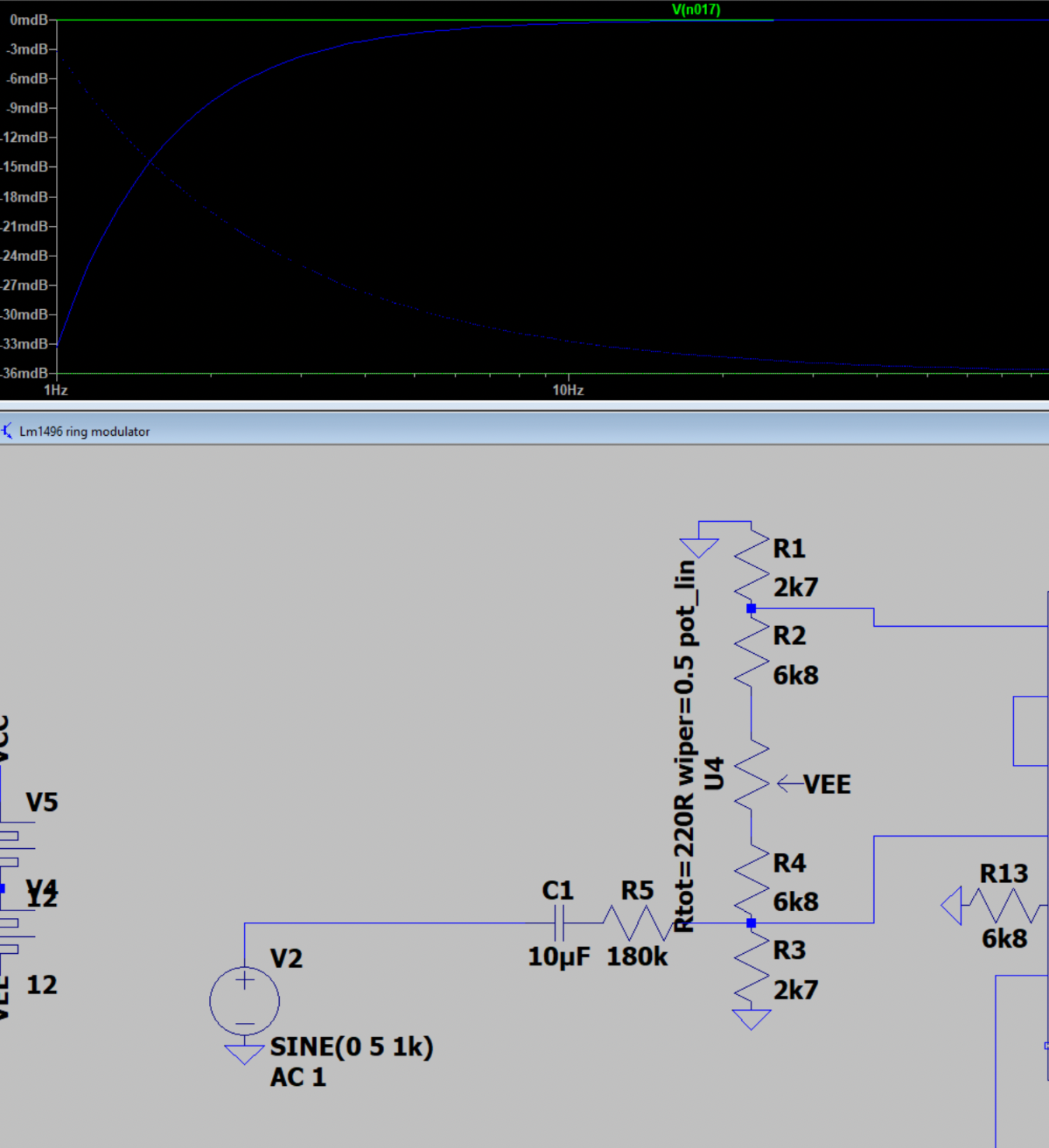
I need to test the range of the CEM3340 based VCO with various pots at their min/max and also replaced with resistors or just leftout.
The pots in question is
- Osc scale trimmer, located on the board
- HF tracking trimmer, external. The Prophet 5 does not use this
- The 500k CV input offset trimmer. The reference design uses a 360k here, the P5 uses a 357k.
Now, for some reason there is a lot of noise on the board outputs (the CEM itself is clean), but even so I am able to measure the frequencies.
Update: The noise is still there when switching to a different VCO PCB.
For all tests, unless specified, I'm running with
360k resistor instead of 500k pot
HF trim center (5k/5k)
27k CV input, meaning the CV should span 18.5 octaves if perfectly tuned (and if that's supported by the VCO, which it isn't).
A cold VCO, i.e. turned on briefly to measure but otherwise off.
PS: My resistors are to 12V, not 15V. Also, I have a 1M5 hardwired to -12V so basically the same as the Prophet 5 (though that uses -15V)
Test 1
Osc scale trimmer (10k) fully counter clockwise
Max period: 264ms (0V): 3.79Hz
Min period: 28.4uS (2.8V): 35.2kHz
Test 2Osc scale trimmer aprox center (so around 29k to -5 from pin 1)
Max period: 492ms (0V): 2.03Hz
Min period: 28.2uS (3.6V): 35.36kHz
Test 3
Osc scale trimmer fully clockwise: (10k top, 0k bottom, so 24k from pin1 to -5V)
Max period: 650ms (0V): 1.54Hz
Min period: 28.4uS (4.5V): 35.2kHz
Test 4
Osc scale trimmer fully counter clockwise
HF trim trimmer fully counter clockwise (0k left to summer, 10k right to HF tracking)
264ms / 3.79Hz
28.4uS at 2.78V CV
Test 5
Osc scale trimmer fully counter clockwise
HF trim trimmer fully clockwise (10k left to summer, 0k right to HF tracking)
265mS / 3.79Hz
28.7uS at 2.6V: 34.8kHz
Test 6
Osc scale trimmer fully clockwise
HF trim trimmer fully counter clockwise (10k left to summer, 0k right to HF tracking)
649mS / 1.54Hz
30uS at 4.8V: 33.3kHz
Test 7
Osc scale trimmer fully clockwise
HF trim trimmer fully clockwise (10k left to summer, 0k right to HF tracking)
656mS / 1.54Hz
31.1uS at 4.1V, not possible to get lower: 32.2kHz
Test 8
Osc scale trimmer approx center
HF input directly to GND
457mS / 2.19Hz
28.7uS at 3.8V, 28.4uS at 5V: 34.8kHz
Test 9
Osc scale trimmer fully clockwise
HF input directly to GND
VCO has been on for a bit
4V gives 20.8kHz
Then
51.8uS = 19.3kHz (not sure if I changed the CV so not very informative)
29.8uS is max = 33.5kHz
Test 10+
After staying on for at least 30min
656mS / 1.52Hz
29.2uS max
4V gives 52.27uS so 19.1kHz
Little change from intitial, cold masurements, still tunable over full range.
Then fully counter clockwise osc scale trimmer:
263mS, exact same as with cold VCO.
Conclusion
I may just go without HF tracking (connect to GND) and shorting bottom two pins of Osc scale pot - or use a 10k for higher precision tuning at the sacrifice of lowest possible note. All options seem to allow for plenty of digital tuning.
Update: Resistor instead of Osc scale trimmer
I did some measurements over the full range of the oscillator, first with the trimmer at its maximums, then with three different resistor values. For each, I calculated an "expected frequency", setting the measured frequency closest to 440Hz as 0, then I calculated an error as 100*(expected - measured freq) / expected.
 |
Error with pot at extremes (blue and red) and then with a 3.9k resistor (breakdowns are when we reach the max VCO frequency of approx 35kHz)
|
 |
Error using three different resistors
|
The best result was reached using a 2.7k resistor for a total of 26.7k between input and -5V. As the graph shows, we are within around 5% of the correct value and it fluctuates around 0, so I don't think we can get any closer. All measurements are done by manually setting the CV and measuring ms as the distance between two tops in Logic2, so there is a significant source of error there as well.
What I DONT know is if this is if this is consistent between VCO chips and VCO PCBs, so perhaps its best to keep the pot. If I decide to redo the PCB though, I think I'll go with a fixed resistor here.
Update: Double capacitance
I had forgotten that the VCO PCB comes with an on-board cap, so the external cap is not necessary. This means that all measurements above are for a 2nF cap instead of a 1nF, meaning the frequencies measured are half of what they will be with a 1nF cap (but not sure what the max frequency will be)
With a new AS3340 and only one 1nF cap, the lowest frequency is 185.3ms = 5.4Hz. Max is 15.2uS = 65.79kHz. The tracking with a 2k7 resistor is similar to the 2nF version and also similar to that of the other AS3340 which is good. There is a difference of around 3% (2Hz vs 2.7Hz) for the lowest frequency between the two devices though.
 |
The tracking is similar, 1uF may even be a tad better - but the frequency range is different (2Hz to 32kHz with 2uF, 5.4Hz to 66kHz with 1nF)
|
Range
Both VCOs top out at 3.25V CV.
With a 2nF cap the range is 2 to 32kHz. The bottom is 2-3 octaves lower than necessary unless the VCO is used as an LFO.
With a 1nF cap the range is instead 5.4Hz to 65kHz which is at least one octave more than necessary on the top of the range.
The higher the range of frequencies covered by the CV, the less accurate the CV will be. Noise will also affect the CV more. Thus, we should try to keep the CV within the usefull range while still allowing room for trimming.
Since the lower range is at 0V CV, we'd have to mix in an offset to rise it. As for the top, we can replace the 25k input (which gives a theoretical range of 20 octaves) with a smaller one.
Let's say we want a useable range from 20Hz to 20kHz. And then we would like an additional octave at top and bottom for tuning. Thats 10 usable octaves plus 2 for tuning.
With a 100k 1V/oct summing point we get 10uA per octave. 12 octaves needs 120uA, and to get this from a 5V we need a 5V / 120uA = 41.67kOhm resistor. Using a 39k resistor gives us 128uA (or 12.8 octaves). 33k gives 151uA (or 15.1 octaves).
Either of these may be fine, it all depends on how much the VCO drifts.
A quick test with a 39k resistor gives a range of 5.4Hz to 38Hz as expected.
Adding a 470k resistor between a 5V reference and the CV summing point rises the bottom to 11.5Hz and puts the top at 66kHz. I think this is a good compromise.
Update: My reference voltage is 2.5V, not 5V, so using a 270k resistor instead is better.
Sync
Connecting a function generator to the VCO sync inputs, I got the following:
Hard sync is only triggered on fast falling edges. This means that the input must either be a pulse or a rising saw. Double check what the DCO outputs!
 |
Sync is triggered on the falling edge of the input square wave
|
CEM Hard sync
 |
expected input (bottom) and effect on saw wave (top)
|
CEM Hard sync is currently not working very well, but I found this post http://atosynth.blogspot.com/search/label/VCO saying I had the same problem earlier and that adding a 1nF cap in series with the input may fix things. Anyway, my experience is this:
For positive going sync pulses (with PWM making the positive going part 10%), the "neutral"/ 0V part must be less than -0.66V (which is eerily similar to one diode drop).
 |
Top is triangle output, the small dips are the classic CEM hard sync effect of positive going pulses. Zero must be around -0.7V
|
If I drop the lower level to less than -1.63V it stops working again. But - if I reverse the pulse so the 10% part is the one dropping, and set the MAX value to <-0.66V, it starts working as it should again.
 |
Negative going pulses, zero must still be about -0.7V negative for things to work
|
Adding a 1nF input cap to the cem hardsync input
That fixed everything, now it looks like this, given a square wave input
Frequency modulation
Exponential FM through a 100k resistor works as expected, giving a +/-5 octave FM if VCO is trimmed properly.
 |
Exponential FM
|
Linear FM did not work out of the box. If input is < -1V through a 120k resistor the output flatlines, I had this in my design and it does not work. So what DOES work?
 |
Linear FM, VCO flatlines when FM input is too low
|
About linear FM in the CEM3340 manual:
The input resistor should be selected to produce a current equal to +/- the reference current when the max input signal is present.
The reference current is set using R_r. In the datasheet, the reference current is 15V / 1M5, or 10uA. Since I'm still using a 1M5 resistor but elected to use a 12V supply instead, I have ended up with a 12V/1M5 = 8uA reference current.
 |
R_r is the reference-setting resistor
|
In the original circuit, the linear FM input resistor is set to 1M. To get a +/-10uV input here would mean the input would have to be +/-10V.
For my oscillator, the linear FM input will be max +/-5V, and I need to match a 8uA current. U/I, or 5V / 8uA = 625kOhm, which means I should use a 470k and a 150k resistor in series.
 |
Linear FM with a 620k input resistor works fine.
|
One more thing - I want to be able to do linear modulation with CV. I therefore have to sum the input before 620kOhm input. Also, the CV is 0 to 5V when it should really be -5 to 5V. Thus, I should set CV gain to 2 and subtract 5V to center it. But the 100nF cap at the lin FM will filter out any DC component, so centering does not do anything. Instead, the CV from the CV generator should stay at 2.5V when not in use. It must also be amplified to 0-10V. That way it stays at 5V when 'idle' and can drop by 5V when in use.
PS: Slow moving lin FM will not be possible.
PPS: Centering the CV won't do any harm, it just won't do any good either, except keeping the lin FM input a bit further away from the rails when summing with another input.
Also - If I use a normal inverting summer, the CV will be reversed. This can be fixed digitally. The analog input will also be inverted, but I don't think that's an issue.
Noise issue
 |
The noise is present on the frequency CV as well as on the output
|
 |
The CEM saw output is completely clean, so the noise is introduced later
|
The same noise is present on the -5V reference voltage, with an total offset of around 25mV.
The noise on the -5V line is not affected by the oscillator frequency
The noise on the
Changing the reference op amp did not change anything
Connecting the scope to the output through a 1k resistor has no effect.
The noise is 80kHz
Buffering the output does not change anything.
The noise is present on the CV even when not connected.
The noise is not present on the 5V reference, but it is present on the -5V/Vee input. Replacing the inverting op amp does not change anything:
When removing the VCO PCB from the breadboard, the -5V stabilizes and the noise disappears from the CV:
Something weird is going on. While tweaking the frequency CV, for a brief moment, the noise disappeared. This happened a couple of times. At the same time, the CV has stopped working after I put the PCB in the wrong position on the breadboard. Very strange.
Oh, but now something happened. Instead of tapping -5V directly from the inverting op amp, I buffered the voltage in a second op amp. Now the noise is gone! (Offset is still wrong though. Perhaps the CEM wave outputs are too low when not running from 15V?).
CV input seems dead though. I need to try a different AS3340 chip but I can't find them...
Noooo! The noise is back! But unplugging and plugging back the -5V made it go away again. Something is ringing.
But when moving the probe from triangle to saw output, noise came back.
Ooh, touching the summing point of the 5 to -5V inverter op amp makes the noise come back (touching the other side of the feedback resistor doesn't.
I think that, in any case, I should reconsider using an op amp for the negative supply here!!! I'm actually embarrassed I ever did.
Wave amplitude and centering
The output from the CEM is 0 to 8V for saw and 0 to 4V for triangle:
The datasheet says 0-10V for saw and 0 to 5V for triangle. In other words, using +12V instead of +15V has reduced the amplitude by 20%, which screws up my centering and amplification. D'oh.
The output from the pcb is -3 to 5V for saw and triangle, -4.4 to 4.8V for square. Unfortunately, since we're using the 0-crossing of the triangle for pulse width generation, the pulse width is also wrong.
Fixing it:
- Ok with positive summer but must have high input impedance. Same when using saw for pwm
Running the CEM3340 from +/-12V instead of +12/-5V
The CEM3340 datasheet uses a 820Ohm resistor from pin 3 to -15V. This works with my version as well (and the hard sync transistor may be connected to -12V instead of -5V without any issues).
However, I had a hard time getting the oscillator to track - I increased the 2k7 resistor on input 1 all the way to 22k (=22k+24k total), and while this made things better, I just couldn't get back to the 1V/oct expected. To stop wasting time I've decided to go back and use a 79L05 to generate -5V on the PCB itself.
However - this gave an unexpected error. Without a 100nF cap on the 79L05 output, the CEM just would not start oscillating!
With -5V from an inverting op amp, it works:
 |
Red is saw out, orange is -5V from op amp
|
With a 79L05 without a cap on the output, the CEM3340 just doesn't start oscillating:
 |
Red is saw out, orange is -5V directly from 79L05 (without a 100nF cap to gnd)
|
Adding the cap makes the CEM3340 start as it should
 |
| Red is saw out, orange is -5V directly from 79L05 (WITH a 100nF cap to gnd) |
Final values
After a lot of measuring I've ended up with the following values:
- 5V negative PSU (79L05)
- 39k CV input resistor
- 2.7k + 24k tracking resistors (Though a pot may still be a good thing)
- 270k to 12V pitch offset resistor
With these params I'm able to get 12Hz to 20kHz, 20kHz is at a little more than 4V CV so still room for tuning.
I tested two different AS3340s, and they differ slightly in both tracking and base note (CV=0) so it may still be necessary to use a trimmer in place of the 2k7.
 |
Tracking is pretty similar
|
 |
Frequency is fairly even too
|
 |
Actual values
|
 |
Tracking with a 25k CV input resistor, 0.25V gives almost exactly 2 x frequency, meaning 1V/octave at 100k is pretty accurate.
|