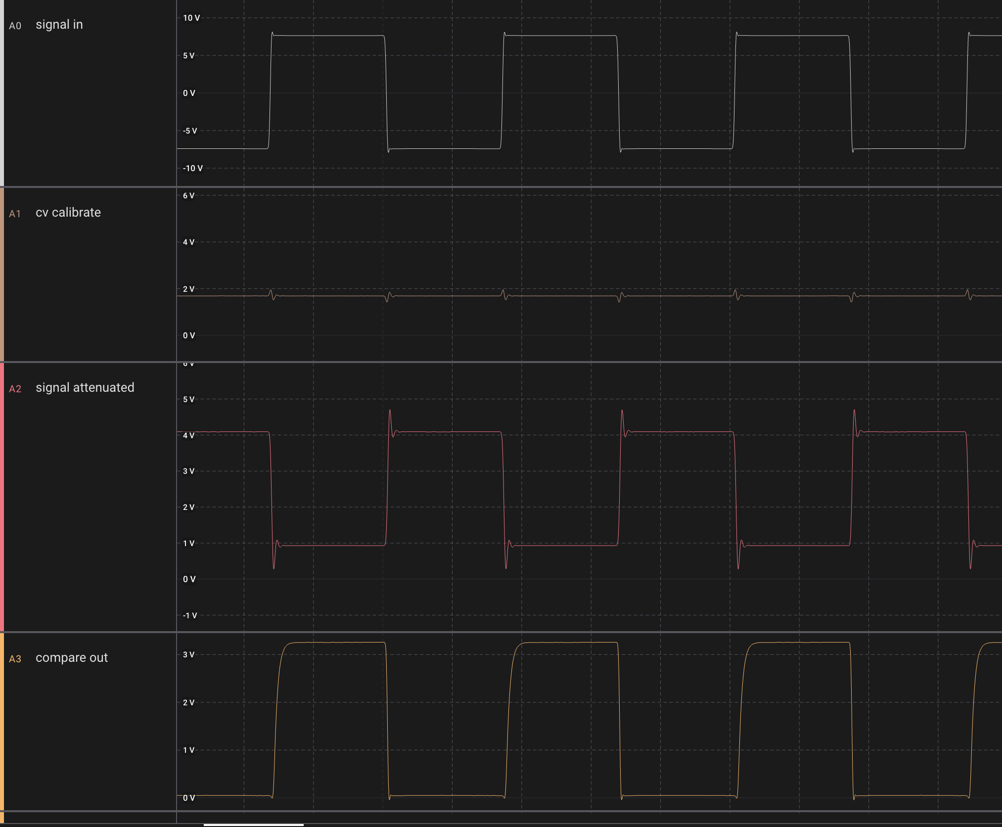
Max output of signal generator is +/-10.4V
Is attenuated and shifted to -0.3/+4.7V (inverted), so a full range input gives a 0-5V output, meaning we can compare bipolar amplitude of the whole signal using a 0-5V CV.
Input CV is 0 to 5V (or slightly less, around 4.6V as we're using a 47k/33k voltage divider from -10.8V)
10k pullup to +12V initially
 |
Approx 2.5V CV gives the expected 50/50 duty cycle on the output
|
Rise time on output (with probe connected) is 1.5uS (with scope connected in parallel, rise time increases to 6uS). This is with a 12V output
Reducing CV to 0 completely turns off output
A signal that is always less than the comparator CV leaves the output fully on
A 3v3 pullup voltage (compatible with the teensy) gives a rise time of around 2.5uS when using a 10k resistor.
A 1k resistor instead gives a rise time of 560nS:
Something to remember: When doing comparisons on a slow moving signal, we may get multiple triggers during the transition. Here we compare a 8Hz triangle wave:
If we use a square wave instead, it cleans up - meaning frequency counting should be done using square waves (unless using hysteresis). This is a challenge if we intend to use resonance sine wave for frequency tuning the filter.
On the Logic16 probes I get double triggers even when sinewave frequency is as high as 10kHz (with the 1k resistor.
With the 10k resistor it seems that we're fine all the way down to 100Hz, some double triggering at 50Hz.
My thought is - double triggering is mostly important for frequency counting, which, when done with a square wave seems to work fine from at least 10Hz to 30kHz (probably even further) with a 10k resistor
For other cases we mostly want to do amplitude calibration, which does not care about doble triggers.
We do get a bit of ringing on the attenuated square wave input at 30kHz, let's see if we can remove it with a LPF:
When we put a 22pF cap in parallel with the 25k feedback resistor, we get this (cutoff is slightly less than 300kHz:
Hysteresis
With a 100k resistor from pin 2 to 7 (positive feedback) on the comparator, while still using the resistor divider on the CV input, we get a stable comparator even as low as 2.5Hz. However, the comparator CV changes wildly from 2.2 to 2.7V during switching:
When removing the voltage divider and just using the output from the CV buffer, the CV stays still but the double triggering is back:
But when removing the 100k resistor completely and just using the raw buffered CV, we reduced doble triggering to almost 0 even at 8Hz:
Then, with a 10pF cap in the positive feedback (between 2 and 7), double triggering disappeared completely, even at 1.5Hz
The output rise time however is increased to around 3uS:
Though - checking again without the cap but with direct CV buffer input, it still seems like the rise time is around 2.5uS. That means that adding the 10pF cap does not significantly increase the rise time.
Using a 50pF cap instead gives an even better result, but gives a rise time of 6uS.
Conclusion
There are a lot of unknowns when it comes to capacitance here, there may be capacitances on the breadboard that messes with my result. Even so, I think I'll try with the 10pF cap on the voice board.
EDIT:
Oooh, we have a serious issue here. The edge is not fast enough for the teensy, we get several interrupts per transition.
Even worse, once I remove the Logic 16 probe, we get a dramatic increase in interrupts, meaning the probe's capacitance filtered out a lot of noise. I need to revisit the hysteresis idea I think :-/
TODO:
Check if hysteresis is available on the TCA9539, and if we can do frequency counting at 20kHz with the TCA9539. If not, we need to connect calibration directly to a pin on the teensy