Sunday, March 19, 2023

LM13700 12/15V simulations, second try

Before converting the JP6 filter to 12V, I wanted to know a bit more about what happens when changing the supply of the LM13700 from 15V to 12V. (For simplicity, throughout this text I will say 15V and 12V when I actually mean a +/-15V and +/-12V supply voltage).

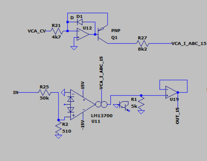
As a first model I used the Xonik VCA.

Xonik VCA

I first calibrated the circuit for unity gain at 5VCV, 15V supply, then updated it for 12V by replacing the diode bias resistor and doing slight changes to centering. (Actually, I made the 12V first then calculated a new diode bias resistor by first finding I_d as 11.3V / 12k = 0.942mA, then finding a new resistor as 14.3k / 0.942mA = 15.18k. The voltage across the resistor is said to be one diode drop away from the supply voltage).


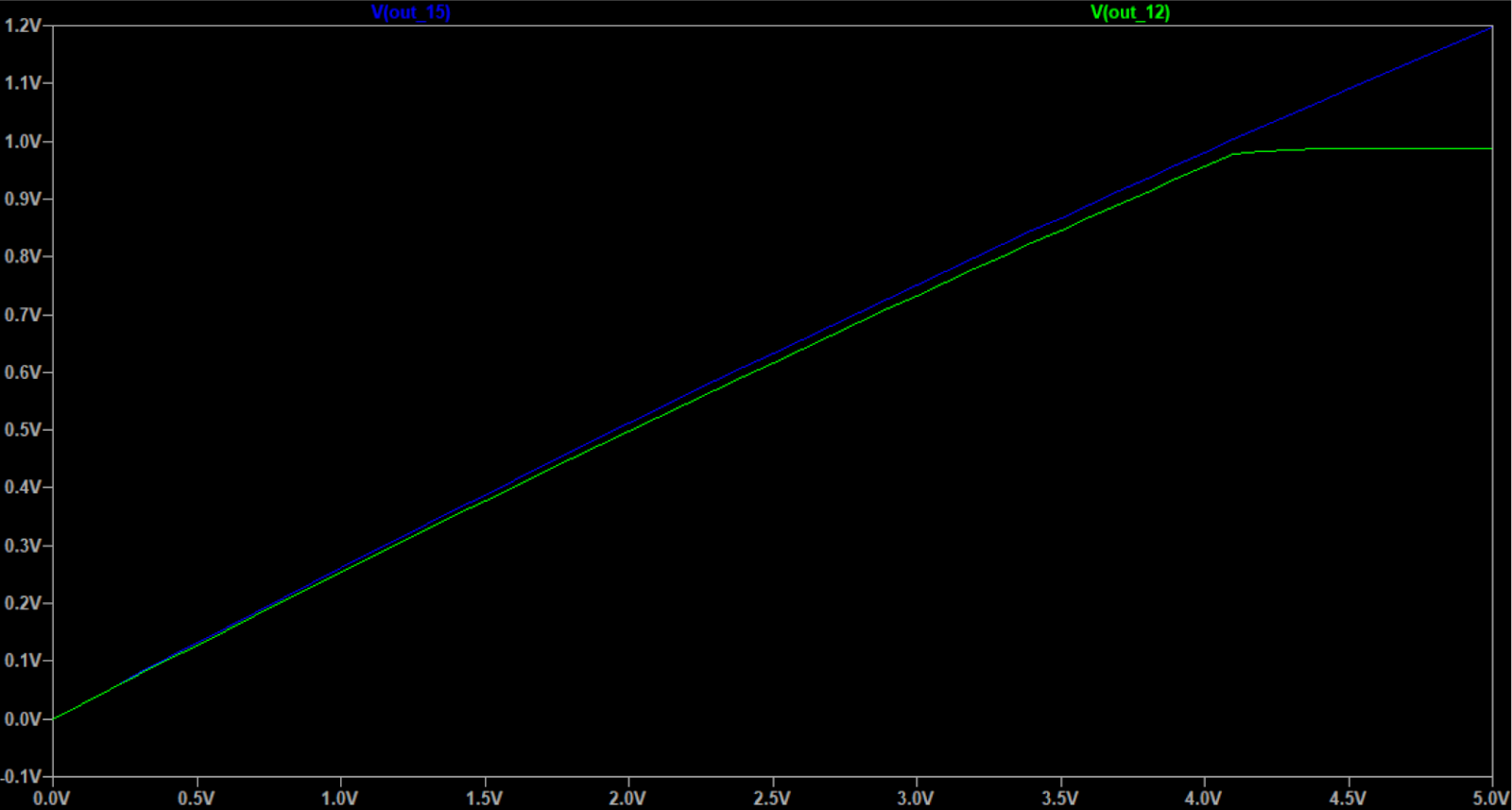
The output is also almost the same, with max output of the 12V being 0.98V instead of 1V:


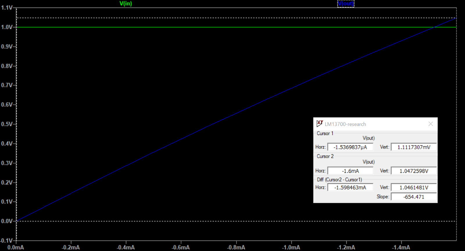
I_abc for both 12 and 15V are exactly the same:


The voltages around the R_abc however, are very different as V_abc changes.


V_abc - these are fairly constant but drops abruptly when CV gets very small (the simulation used a resolution of 0.1mV, in reality the dropoff is even closer to 0VCV.


By manually tweaking R_d I was able to get an exact match with unity gain for both voltages. The R_d for 15V is slightly lower than expected. Perhaps a different value than 0.7 for diode drop is used in the simulator?


Here are updated measurements.

CV inputs

CV Supply Icv (=-I emm) I base Iabc Vabc V coll V base
0V12V0V0V0A-11.29-11.29V46.9nV
0V15V0V0V0A-14.27V-14.27V46.9nV
0.1V12V-21.7uA-224nA-22.4uA-10.47V-10.28V-675.9mV
0.1V15V-21.7uA-224nA-22.4uA-13.47V-13.28V-675.9mV
5V12V-1.064mA-10.5uA-1.053mA-10.26V-1.62V-775.6mV
5V15V-1.064mA-14.3uA-1.053mA-13.26V-4.63V-775.6mV

I've added an additional step at CV=0.1V, as the voltages around R_abc abruptly drop below this. This step shows that V_abc is fairly constant and not too far from the ideal supply-1.4V. 

So, what can we see from this? The only thing that changes when we switch supply (after replacing with updated R_d) is V_abc (which in turn changes V_coll). I_abc vs gain stays the same.

They also stay the same even if I_d changes.

Signal voltages

  • input is -5 to 5V.
  • CV is 5V
  • +in is connected to input through a 27k resistor and has a 510R to gnd
  • bias input is connected to 12/15V through 12k/14.75k resistor
  • Output is to gnd via 28.7k resistor, buffered.

Supply +in -in bias I out (to gnd) V out
12V 175mV to 275mV

(191.7uA to -175uA in 27k, 343uA to 539uA in 510R, -535uA to -365uA into +in)
184.5mV to 265mV

(373uA to 536uA)
1.03 to 1.12V

(-914.5uA to -907uA)
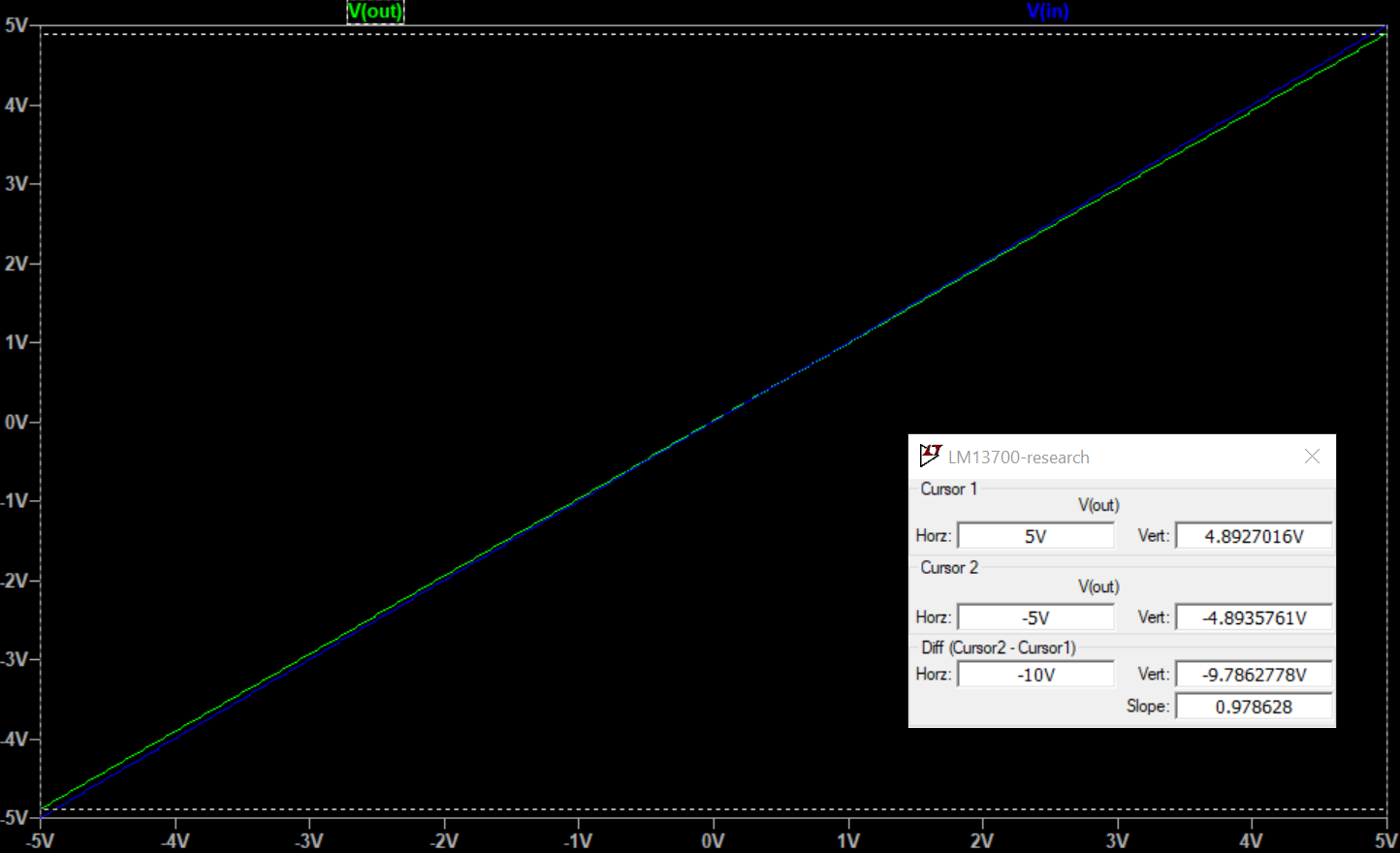
176.1uA to -174.8uAV out: -5.05 to +5.02
15V183mV to 283mV

(191.9uA to -174.7uA in 27k, 358.5uA to 554.5uA in 510R, -550uA to -380uA into +in)
191.9mV to 272.7mV
(391uA to 556uA)
1.04 to 1.13V

(-946.8uA to -940.7uA)
172.3 to -172.2uAV out: -4.95 to +4.94

These are practically identical, I assume that a bit of tweaking for R_d would make them exactly the same. Nice! That means that the same I_abc gives the same gain as long as I_d is tweaked due to the changes in supply voltages.

Juno expo converter

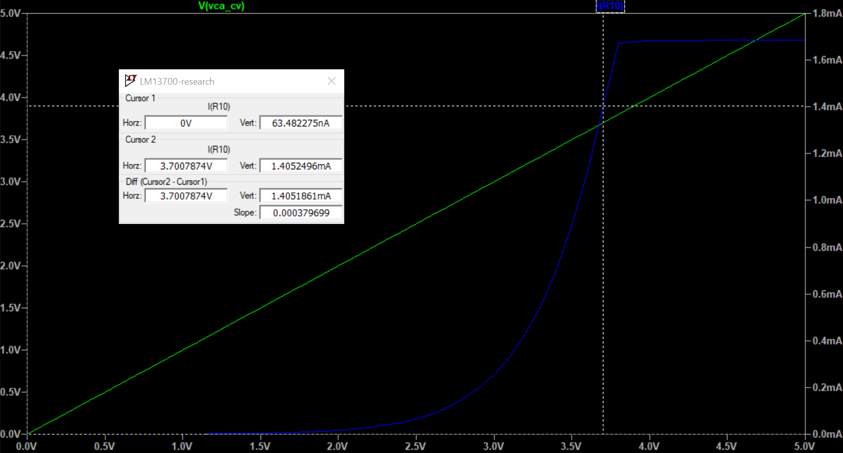
My juno expo converter is made to go to max, so it flatlines when CV > 3.5V. With adaptions between 12V and 15V (offset resistor and reference current resistor) they track the CV exactly the same, but the 15V version goes slightly higher.

15V and 12V expo circuits (VCA linear control circuit is still present but not used)

Both flatline when CV is high enough but 15V goes further


Voltages around R_abc are different, as expected. I've reduced CV to 0-3.5V to stay within operating range

V_abc is still fairly constant, with about 0.5V variation

V_coll

Again, as long as I_abc stays the same, the output stays the same. The expo converter generates the same I_abc as long as reference current and offset voltages are adjusted (and we stay within a range where voltages around R_abc can change enough to generate I_abc).

But we can do more! If we replace the 8.2k R_abc with a 6.4k, we allow a larger current through it with the same voltage. Then we get the exact same range as with 15V!
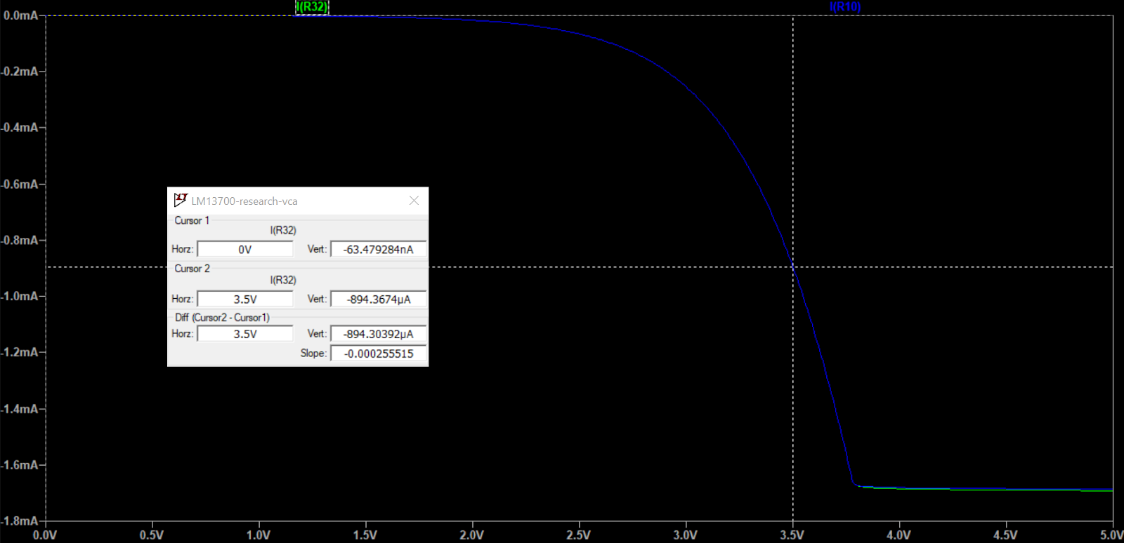

I_abc are now equal for both 12V and 15V

Outputs are equal too

In other words, we could probably do the same for the VCA to get the same range there as well. Turns out, we can:

Xonik VCA again


Going back to the version from my failed post, which uses this circuit:


and has this output:


If we just replace the 8.2k R_abc resistor with 6.4k, it works as it should:


Gain without I_d

First, I tried a version of the circuit with and without I_d
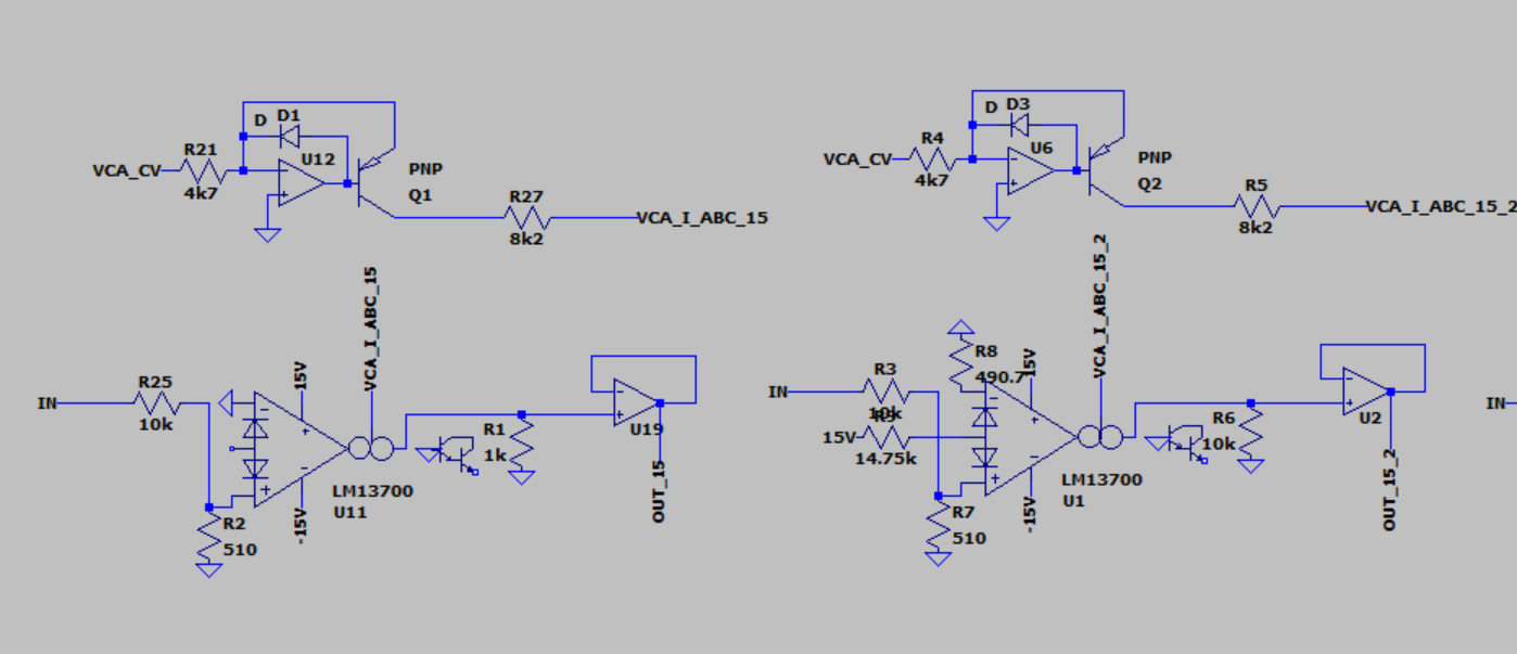

Two versions of the 15V circuit, tuned to be approximately the same

Signal input is -1 to +1V. From this plot it is quite clear that the one without I_d is not linear across the signal range:

The I_d version is completely linear whereas the non-I_d version is heavily distorted.


Increasing the input resistor and thus get a smaller differential input gives us a much more linear result:


In the datasheet, gain without I_d looks like it is not depending on supply voltage at all. Here is a plot of a 15V and a 12V version:

12V and 15V versions are very similar (but not 100%)

I retried with a smaller input resistor, 30k. Here is the input and output voltages, you can juuust see that the output is not entirely linear:

Voltage at positive input

Voltage at output, it is slightly curved downwards for the first 50% and then upwards for the rest.

As is expected from the datasheet, when not using a diode biasing current, the input must be attenuated a lot more to keep the gain linear across the signal range.


Gain measured vs calculated


For the version without I_d

Gain is expected to be:

I_out = V_in * I_abc * q / 2kT

where 

T = 283.15K (for 25C)
k = 1.38*10^-23 (Boltzmann constant)
q = 1.602*10^-19 (electron charge)

I_out = V_in * 19.47 * I_abc

(for T=300, gain is 19.3 * I_abc, which is almost exactly what is used in 8.3.3 and 8.3.4 in the datasheet).


This gives us for the 50k input version:

V_in+ is -11.18mV to 8.56mV, diff is 19.75mV
V_in- is -1.4959mV to -1.059mV, diff is 0,4369
V_in is -9.69mV to 9.62mV, diff is 19.31

I_abc = -1.05mA

Expected out is

I_out = 0.01931V * 19.47 * 0.00105A = -392.3uA


Measured output current

I_out = 213.13uA -149.72uA, diff is -362.85uA

The output current is independent of the R_out resistor, it only sets the output voltage.

This is fairly close to what the gain formula predicted, which is good.

However, I still have NO clue as to how I can find V_in+, V_in- or the differential voltage V_in. Without the last one this formula seems useless.

The same goes for the "missing gain formula" for the version with I_d. It needs the current in the input resistor, but how do I get that when I don't know the voltage at V_in+?

Closer measurements and useful V_in

UPDATE: After doing the version with I_d, and the email from Iain described below, I did some further simulation of the circuit. This time with both input offset resistors to ground in place. (I think the results would be close even without the negative one, the output would just be less centered).


Since the formula for I_out depends on the differential voltage, we cannot assume that the whole voltage drop is across the input resistor. 

However, the voltage at the negative terminal is much smaller the positive terminal, so we can choose to ignore it. We can also ignore the effect of the input transistor on the resistor divider formed by the input resistor and the resistor to ground. This means that an approximation of the differential voltage is

V_diff = V_in * R_g / (R_g + R_in)

where R_g is the resistor to ground.

When using the simulated differential voltage in the calculation, we get within 12-13% of the measured output value (for 500R resistors to gnd). Using the voltage divider voltage the error is 14-15%. I say that is plenty good enough :)

PS: The output current is not centered around 0A, this can be solved by either biasing or using a cap on the output.

1V sinewave input vs current output. Output is not centered. Using R_in=200k and R_g=1000


Simulated and calculated results.

PPS: The input voltages are not centered around 0V. To compensate for this, all voltage and current measurements in the spreadsheet above are the difference between the results for -1 and +1V input. Ideally, they should have been the averages, now they are twice that, which is why I've put 2x in all the columns. The formula still holds though.

With and without resistor from IN- to ground. Without (blue) the output has a larger DC component


For the version with I_d

Now, I wanted to see how much off the "missing formula" was and how it worked with the simulated results, so I did a lot of measurements using 250, 500 and 1000R resistors to ground, and 12.5k, 25k, 50k and 100k input resistors. I also tried both 12V and 15V supplies but they turned out the same.

I also wrote Iain Sharp and asked how he calculated I_g. He very kindly answered me almost immediately (thanks again Iain!), and the main takeaway from his long and detailed answer was that since the input voltage drop is so large compared to the DC offset at the input, I_g can be approximated as V_in / R_in. Nice!

(In general, Iain Sharp confirmed my suspicion that no one really knows exactly how the LM13700 works and everyone just experiment to get the wanted results. Incidentally, he read the first part of this post and got very worried that I do such detailed simulations without actually breadboarding anything as simulations are not the real deal. I will definitely test stuff in real life).

Anyhow, here is a table that includes both the measured voltages and currents, the expected output voltage using the formula but with the measured I_g, and the expected output using the formula with I_g as V_in/R_in:


All measured numbers are the difference between the results of -1 and 1V inputs, as I have not AC coupled anything. This means everything is double, which is quite confusing I guess. But the results are still valid.

There are a lot of numbers here, but the most interesting are:
- For the "standard" 500R resistors, the error is around 16-17%.
- There is only about 0.5 to 3 percentage points difference between using the simulated I_g vs the V_in/R_in one. A bit worse for the 1000R resistors and better for 250R.
- The simulated I_g makes the error constant as long as the resistors to gnd don't change.

A better I_g

Now. I had a look at what V+ voltage to expect if using a resistor voltage divider and ignoring that the center is connected to a transistor and a diode.

Interestingly, the result is almost exactly twice what we get when measuring. If we wanted to get a slightly better approximation for I_g (and one with a consistent error as we change the input resistor), we could use

V+ = V_in * R_offs/(2*(R_in-R_offs))

I_g = (V_in - V+) / R_in

where R_offs is the resistor from V+ to ground.

We still have a bigger problem with the formula though, so it probably isn't worth it. Just find an approximate output and simulate/measure your way to the correct values!

Other things to consider

The output in the version without I_d is not centered around 0, that is probably why there is a trimmer in the output VCA of the Juno filter, to add a DC component

Also, perhaps the filter does not use linearising diodes on the VCA as that allows a soft distortion similar to the non-linearity described above when the filter is overdriven.

DC operating point


The voltage input (base of the transistor) is not at 0 when the input voltage is removed, in other words, the input voltage at that point is centered around something else. If you need to find this, Iain Sharp had a nice way of thinking about it:


If you remove the input, you have two equal circuits around the differential transistors. 

In one leg, you have D1 and R1, in the other D2 and R2. 

Assuming R1 = R2, I_d is split equally between the two legs. We can also choose to ignore I_base as it is much smaller than I_d.

To get to ground, I_d must pass through R3 and the parallel equivalent of R1 and R2. Since R1 = R2, R1 || R2 is simply R1 / 2.

The combined voltage drop across the resistors is V_supply+ minus one diode voltage drop (roughly 0.7V) across the diode*. That gives us the formula for I_d:

I_d = (V_supply+ - 0.7V) / (R3 + 0.5 * R1)

Since I_d = I_R1 + I_R2, and I_R1 = I_R2, I_R1 is simply 0.5 * I_d

We can now find the voltage at the transistor base:

V_b = R1 * I_R1 = 0.5 * R1 * I_d = R1 * (V_supply+ - 0.7V) / (2 * (R3 + 0.5 R1)) 

V_b = R1 * (Vsupply+ - 0.7V) / (2R3 + R1)

* For the voltage drop I've assumed that 'reordering' the resistors and diodes so that it's R3 -> R1  || R2 -> D[1,2] and then calculated the equivalent resistance. I think this is ok but not 100% sure of it).


Tested circuit, input is +/-1V sine wave


Input at V_b, centered around 452mV


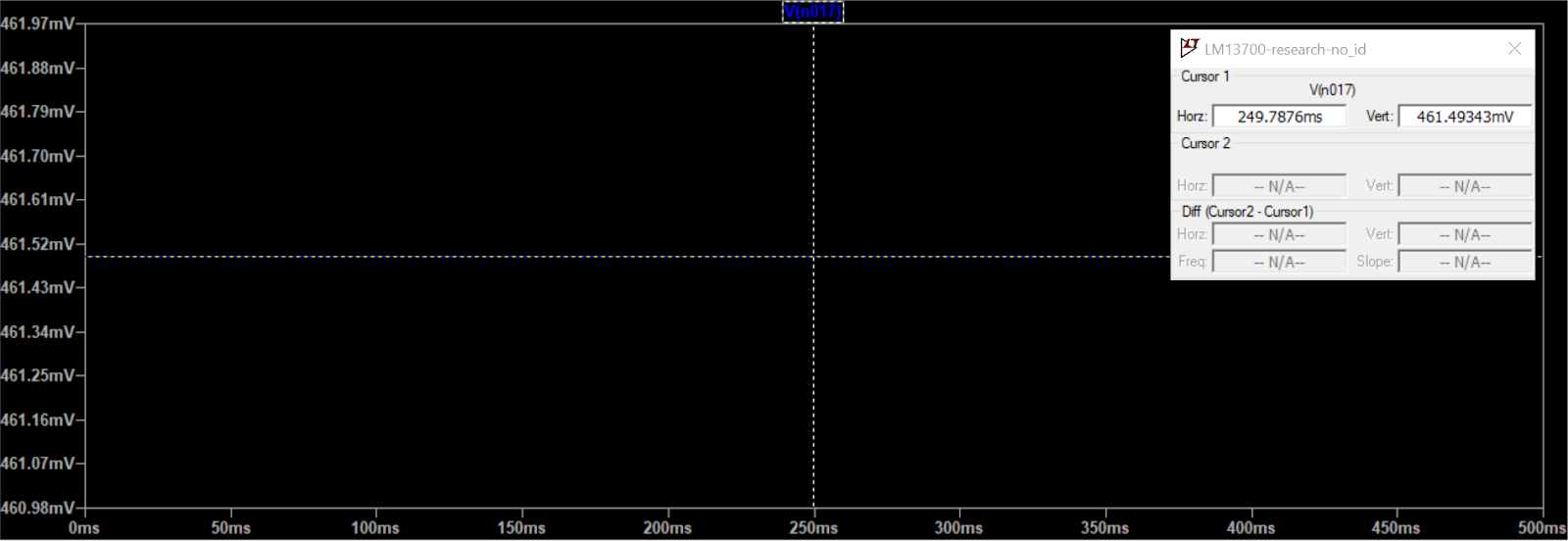
Circuit with input and R25 removed, shows 462mV DC offset

Measurements and calculations - for all lines with a value (100k, 50k, 25k) the input was connected to gnd. For the "no input" lines, input and R25 was removed. V+ calc is within 0.01V of measured value

Value at start of header lines is R1,R2.


Thursday, March 16, 2023

UPDATE: Flawed - LM13700 simulations, 12/15V supplies

UPDATE: A lot of the values in this post are wrong, as the 5V CV in the 12V circuit made it flatline after about 4.5V CV. I will do a new post with a corrected circut but keep this to be able to see what I originally thought.

I_abc

V_out


Before converting the JP6 filter to 12V, I wanted to know a bit more about what happens when changing the supply of the LM13700 from 15V to 12V. (For simplicity, throughout this text I will say 15V and 12V when I actually mean a +/-15V and +/-12V supply voltage).

As a first model I used the Xonik VCA.

Xonik VCA

I first calibrated the circuit for unity output at 5VCV, 12V supply:


I then tried the same circuit with a 15V supply without changing anything else:

Slight offset of output when 15V supply, slightly reduced gain (surprisingly)

Finally I tweaked the resistors to get a centered output with 15V:

Centred output, 15V supply

Centred output, 15V supply - circuit

EDIT: After completing all measurements I went down the rabbit hole that is reading the datasheet. I discovered that (not that surprisingly really), the gain (transconductance) of the circuit is strongly dependent of the diode bias current. In my 12V version of the circuit this is set to 11.3V/12kOhm = 0.942mA (11.3V is one diode drop short of the positive supply voltage 12V, as anode of the diodes are 0.7V above 0), so when changing to 15V we need to replace the 12k resistor with a 15.19k one. This does not affect the control current generation but it DOES affect the gain, see the last line in the signal voltages table.

Measurements around the LM13700 on the Xonik VCA

CV inputs

CV Supply Icv (=-I emm) I base Iabc Vabc V coll V base
0V12V0V0V-11.29pA-11.289V-11.289V33nV
0V15V0V0V-14.27pA-14.266V-14.266mV33nV
5V12V-1.515mA-271uA-1.244mA-10.25V-49.9mV-788.7mV
5V15V-1.515mA-15uA-1.500mA-13.24V-942.33mV-784.7mV

These stay the same even if the diode bias current changes.


Signal voltages

  • input is -5 to 5V.
  • CV is 5V
  • +in is connected to input through a 27k resistor and has a 510R to gnd
  • bias input is connected to 12/15V through 12k resistor
  • Output is to gnd via 24.3k resistor, buffered.

Supply +in -in bias I out (to gnd) V out
12V 175mV to 275mV

(191.7uA to -175uA in 27k, 343uA to 539uA in 510R)
184.5mV to 265mV

(373uA to 536uA)
1.03 to 1.12V

(-914.5uA to -907uA)
-205 to 206.7uAV out: -5.02 to +4.98
15V 235.7mV to 234mV [THIS MUST BE WRONG, PROBABLY to 324mV)

(193.9uA to -172.8uA in 27k, 462uA to 654uA in 510R)
243mV to 325mV
(495uA to 662uA)
1.09 to 1.118V

(-1.1589mA to -1.1515mA)
-201.3 to 201.3uAV out: -4.89 to +4.89
15V* 175.6mV to 278mV

(191.7 to -175uA in 27k, 344.3 to 540.8uA in 510R)
184.9mV to 265.5mV
(376.8uA to 541uA)
1.03V to 1.12V

(-920uA to -914.2uA)
246.8uA to -245.4uAV out: -6.0V to 5.96V

*with changed diode bias using 15.19k resistor instead of 12k. 

Something interesting happened when I changed the diode bias resistor. All signal currents and voltages are suddenly the same as for 12V. The control currents/voltages are still different from 12V but they have not changed from the original 15V. The only thing that is different is I_abc. Let's see what happens when we change that to match the 12V input.

Changing the CV to 4.1465 changes I_abc to -1.244mA. Now the output is back at -5 to +5V! Hooray, this means that we have the exact same I_abc to gain tracking for 12 and 15V. In other words, I_abc tracking is the same as long as we use the correct diode bias.


With constant current source for Iabc


Signal voltage and currents (+/- in and bias) don't change.

Current response (Iabc vs output) changes when going between 12V and 15V. 

Examples with 1V input signal and 0 to -1.5mA (12V) and -1.6mA (15V):

12V source


15V source

TODO: Add new screenshot with corrected diode bias current.


With expo converter from Juno


12V

Original expo converter for 12V

CV vs Iabc for 12V, with cursor set at max CV that gives a usable Iabc


CV vs Iabc for 15V but with same circuit and CV as 12V, Iabc is much lower than for 12V

Still same circuit as 12V but max CV for 15V. Max CV is higher than for 12V

TODO: New screenshots with corrected I_d

Now adapt circuit by replacing Rref with 1.5MOhm and offset with 412.5k to keep inputs the same

Adapted circuit to keep 15V same as 12V

Adapted circuit (15V) with same CV as max for 12V circuit. Iabc is now -1.41mA vs -1.31mA for 12V. Not that far off but still a few percent.

As above but with max CV for adapted 15V circuit


Voltages 12V

12V: Voltage at right transistor out

12V: Voltage at current input (V_abc)


12V: V_output with input = 1V

Voltages 15V

15V: Voltage at right transistor out

15V: Voltage at current input (V_abc)


15V: V_output with input = 1V


TODO: Explain why voltages after transistor changes (current source?)

TODO: Regne på om I_abc vs gain endrer seg mellom 12 og 15V

Tuesday, March 7, 2023

Filter FM and a dash of VCO linear FM research

It's time to hook up the FM inputs on the low pass filter.

I have an option to use both linear and exponential FM.

The most common option is exponential (v/oct) as this is readily available by mixing oscillator output with filter cutoff CV.

I found a nice post earlier about the use of both types but cannot find it right now, but here is a thread about linear FM at least:

https://modwiggler.com/forum/viewtopic.php?t=119415

FM off

I did initially design the FM input with two SPST (on/off) switches. This allows me to disconnect the input completely, as I was unsure how far down I could get the VCA to go.

Now I've done some calculations:

At 0V, the VCA has -80dB attenuation. That means that a 5V input signal would give a 0.5mV output.

If we've set the modulation to 1V/octave, 1 semitone would be 83.3mV, in which case 0.5mV = 0.6 cent. The input is bipolar (+/-5V) so the total change is 1.2cents.

For VCO tuning/tracking, I've assumed that a relative pitch change of about 3cent is at the limit of human hearing - and that's for VCOs. I think it is probably quite safe to use the VCA as a switch in this case. 

That leaves me with two options 

- either I use a DG413 as an SPDT switch, switching between lin and log - that saves me a single digital control signal. 

- or I use only exponential FM, in which case I don't need a switch at all.

I am currently breadboarding this. Both lin and exp FM works fine, but +/-5V linear FM seems to saturate something so the wave is cut off in some way. I will do a recording of it and add soon. Then I have to simulate the same to see what is actually going on. If I cannot make it work well I will just go for an exponential FM only.

Filter out: DCO1 is filtered, DCO2 modulates filter cutoff. Before red line: Linear FM, after: Exponential (v/oct) FM


Self resonance and exponential FM settings

Self resonancce and exponential FM output

Self resonance and linear FM output


Observations

Lin FM makes the filter "flatline". when the CV (DCO2) is low enough, the filter reaches a zero Hz cutoff, but the CV still goes lower, meaning the cutoff stays at 0Hz for some time - the filter does not support "through zero" modulation. 

PS: The output flatlines when input CV is positive, this is because the reference current is negative and any positive cv "negates" the reference current. Once the sum reaches 0 we cannot go any higher and the output flatlines.


Linear FM: When DCO2 is above a certain level,  the output "flatlines", presumably because cutoff reaches 0Hz before DCO2 reaches its peak.


Some measurements of linear FM CV vs I_abc

I_ref without any modulation is -12V / 1.2MOhm = -10uA (NB: mislabeled as -15V in captures)

With a +/-5V CV and a 120k input resistor, we will get 5V/120kOhm = 41.7uA, or approximately +/-4x the original I_ref. But since we cannot use an I_ref > 0, we get a flat line when the input from the linear FM CV reaches +10uA.


Cutoff CV: 0V, Lin FM CV: +/-5V


Cutoff CV: 2.5V, Lin FM CV: +/-5V


Cutoff CV: 3.5V, Lin FM CV: +/-5V


Cutoff CV: 4.5V, Lin FM CV: +/-5V


In my simulation I have written that we should use an input resistor that is approximately 10x the one used for the reference current, as that is what Yusynth.net uses for his VCO. That is not true.

Yusynth generates his reference current from a 5V source through a 1M resistor, giving a reference current of 5uA. For the linear FM input, he uses a 100k resistor, so a +/-5V input gives a +/-50uA output, which is 10x the normal reference current.

I, on the other hand, has used a CV that gives 4x reference current.


Cutoff CV: 0V, Lin FM CV: +/-5V, but this time we use a 50k lin CV input resistor


Calculations

To get a better feeling of the lin FM range I've done some simulations on the filter circuit. Here is the Frequency CV vs cutoff frequency vs I_control vs A/Hz (through a single cell):

1.0V:    10Hz    259nA    25.9nA/Hz

1.5V:    37Hz    1.03uA    27.8nA/Hz    

2.0V:    150Hz    4.18uA    27.8nA/Hz

2.5V:    604Hz    16.4uA    27.15nA/Hz

3.0V:    2.3kHz    63.6uA    27.7nA/Hz

3.5V:    8.2kHz    223uA    27.2nA/Hz

4.0V:    22.4kHz    639uA    28.5nA/Hz

4.5V:    42kHz    1.3mA    31.0nA/Hz

1.3mA is the highest possible value before we reach a flat top.


If we disregard the first and the last two (>= 4.0V) as we already know that they are not tracking that well, we get an average of 27.5nA/Hz


From my previous work I have that: 

R_linfm is often selected so that I_linfm = I_ref when linfm CV is at its highest (often 5 or 10V), which means that the frequency can be modulated by +/- 100% (the reference current will be between  0V and 2 * I_ref).

This is only true as long as we do not use through zero modulation. 

Also, looking at the Yusynth VCO with its 10x FM, this is clearly not what everyone does.


What are others doing. VCOs:

Rene Schmitz: 

https://www.schmitzbits.de/vco2.html

VCO 1-3: 15V / 1M ref current, 5V / 220k lin FM (15uA vs 23uA, ca 1.5x mod)

VCO 4 (TZFM) 15V / 470k ref current, 5V / 220k lin FM (32uA vs 23uA, or 0.72x mod)


Yusynth VCO

https://yusynth.net/Modular/EN/VCO/index.html

5V / 1M ref current, 5V / 100k lin FM (5uA vs 50uA, or 10x mod)


CEM3340

Pin 13 on the CEM3340 is the reference current summer. The datasheet has a 1.5M resistor to 15V and a 1M + 0.1uF cap to lin FM. In the last paragraph of the datasheet it says "The value of the input resistor should be selected so that the maximum peak to peak input signal produces a plus and minus current equal to the reference current". This is exactly what I have written in my own research on VCOs, so I guess this is where I got it from (?).

15 / 1.5M ref current, 5V / 1M lin FM (10uA vs 5uA, or 0.5x mod. Or, could it be they expected a +/-10V lin FM CV? In that case they follow their own doubling rule.


Ian Fritz

https://ijfritz.byethost4.com/sy_cir2.htm

6.9V / 690k ref current, 5V / 100k lin FM (10uA vs 50uA, or 5x mod)

https://ijfritz.byethost4.com/sy_cir16_teezer.htm

Hard to tell as lin FM is done differently


MFOS

https://hackaday.io/project/47158/gallery#ecedc0e5555ada3907345e3c0c4cda3d

A bit hard to tell, lin FM enters through the middle of a voltage divider??

12V / 1M ref current, 5V / (1M || 100k) lin FM (1M til summer) 


JJ Clark

https://electro-music.com/wiki/pmwiki.php?n=Schematics.XR2207VCOByProfessorJamesJClark

12V / 68k ref current (!), 5V / 10k lin FM (176uA vs 500uA, or 2.8x mod)


Thomas Henry

https://electro-music.com/wiki/pmwiki.php?n=Schematics.ACD4046BasedVCOByThomasHenry

15V/1.5M ref current, 5V / 100k lin FM (with AC/DC switch) (10uA vs 50uA, or 5x mod)


Lots of VCOs here: 

https://electro-music.com/wiki/pmwiki.php?n=Category.VCO


Ken Stone CGS48 VCO and VCF-ish thingie with built in VCO

https://electro-music.com/wiki/pmwiki.php?n=Schematics.Bi-N-TicFilterByKenStone

https://sdiy.info/wiki/CGS_VCO

15V/150k ref current, 5V/100k lin FM (100uA vs 50uA, or 0.5x mod)


Linear FM and "amplitude" in Hz

As described in more detail here, increasing the base frequency also increases the "amplitude" of the modulation (if you think about the FM as a bipolar signal). The higher you get the larger the change is. 

So, what to choose

That's the hard question, isn't it... Right now I'm having a hard time understanding why anything more than a 0-to-doubling of the reference current is used on a non-through-zero FM VCO/VCF. Once we go lower than 0 the average frequency starts to drop and the VCO goes flat. I guess that's an effect as well, but why do we want it? And why on earth would we want 10x the input as is the case on the Yusynth VCO? Hmm.... I guess the only way of finding out would be a proper test.

Update: After a little thinking I think (...) I will try this: Select an R_linfm that gives a I_linfm that is 4x the reference current. That way I can just divide the CV by four (= shift right 2) to get an I_linfm equal to I_ref, meaning that the output of the exponential divider will never be below 0. 

Juno filter FM

Incidently, for the juno filter with a 10uA I_ref, this whould mean a 125k resistor. My current design uses a 120k, which gives a 41.7uA max, or 10.4uA after division by 4. This is very close to the ideal. One could argue that a 130k would be better, making us not quite reach I_ref, but again, it's better to test. It is also possible that a 5V input to the VCAs does not give exactly a unity gain, so 120k, being a standard resistor value, may be good enough anyway.

VCO lin FM

As for the VCO, we have a slight issue. My current design expected a 15V input using a 1.5M resistor, giving a 10uA I_ref. Now, hopefully, I'll be able to tune away the difference, but selecting the proper R_linfm depends on whether I match it with the current design or with a possible updated/corrected design. Anyway, here are the two options:

For 10uA, I could use the same 120k or 130k resistor as for the juno VCF.

For 12V / 1.5M = 8uA i will need 32uA. The correct value would be 156k. The closest standard value is 150k which gives 33.3uA - again, a little high (3.5% vs 4% for the juno filter) but it may work anyway.

Jupiter 6 filter lin FM

This uses the same expo converter as the juno filter. Right now they both use 15V and 1.5M R_ref, giving an I_ref of 10uA. As I've already redone the Juno filter for 12V with a 1.2M R_ref I will probably do the same with the JP6 version. That means that I can use a 120-130k R_linfm here as well.

Moog filter lin FM

The current 15V version has a 1M R_ref, giving I_ref = 15V / 1MOhm = 15uA 

If we switch to an 800k version (or 820k perhaps) for the 12V version, we will keep the I_ref the same.

I_linfm would then be 60uA and we would need an 83.3k resistor.

If we continue using the 1M R_ref, I_ref would be 12uA. I_linfm would be 48uA and we would need a 104k resistor


Thursday, March 2, 2023

Frequency modulation

While testing filter FM I realised that I needed to know a little bit more about what is actually going on, so here we go. I'll explain things using VCO frequency modulation as it is a bit more intuitive, but the same happens with filter FM.

Linear FM

In linear FM, the change in Lin FM CV is directly propotional to the change in frequency. For example, if a 1V increase in Lin FM CV leads to a 200Hz increase, a 1V decrease leads to a 200Hz decrease - as long as the base frequency set by the (1V/oct) Pitch CV stays the same. 

In other words, if the initial frequency is 440Hz, the output should be between 240Hz and 640Hz. What we hear is close to the average of the two extremes (this moves into the field of psychoacoustics apparently, so this is not an exact science or at very least not something I'm proficient in). The average here, at least with a symmetrical waveform, is 440Hz, so the output stays in tune as we increase/decrease the CV.

BUT: Once you change the Pitch CV, 1V no longer corresponds to a 200Hz increase. However, increasing and decreasing the Lin FM CV will add or subtract the same number of Hz so the average stays the same as the base frequency. Also, the relationship between the modulated frequency in both cases to the base frequency stays the same.

For example - if a 1V Lin FM CV adds 200Hz when the base frequency is 440Hz, adding 1V will add 400Hz (one octave up) when the base frequency is 880Hz (one octave up), and 100Hz (one octave down) when the base frequency is 220Hz (one octave down). 

Linear FM stays in tune both as we change the FM CV and the Pitch CV, as long as the modulated frequency does not reach either 0Hz or the upper limit of the VCO pitch or filter cutoff.

Linear FM is usually implemented by modulating the reference current in the exponential converter.


Exponential FM

With exponential FM,  we modulate pitch as "semitones". If we use a 1V/oct input, and FM CV is, say, +/- 1V, frequency will go between +1 and -1 octave of the original frequency. For example, if the original frequency is 440Hz, the modulated signal will go from 220Hz to 880Hz.

What is the effect of this? Well, what we hear is not the original 440Hz tone, but again closer to the average of the two extreme. In our case this means 220 + (880-220)/2 = 550Hz

If we drop the original pitch by an octave to 220Hz, we would expect an output between 110 and 440Hz. The average is now 110 + (440-110)/2 = 275Hz, which is one octave down from 550Hz. In other words, the modulated output tracks the original pitch.

But what if we change the FM CV? If we go from +/-1V to +/-2V but keep the original frequency at 440Hz, we would now get a range of +/-2 octaves, or from  110Hz to 1760Hz.

The average of these is 935Hz, whereas for the +/-1V FM CV it was 550Hz. The perceived pitch increases. Similarly, if we decrease the CV the perceived pitch drops. As long as the CV range stays the same we're good though.

Exponential FM is usually implemented by mixing the FM CV with the normal V/Oct CV.


Through zero modulation

An exponential FM will always halve the cutoff frequency for every 1V decrease of CV. This means that the cutoff frequency will never reach zero.

For linear FM however, which controls the reference current in the exponential converter, cutoff WILL reach zero. 

Through zero modulation means that we detect when the CV changes polarity, and (at least for a VCO) reverse the polarity of the output. The frequency should be the same as for a positive CV of the same magnitude. In other words, we use the absolute value of the CV for frequency, and the sign to control the output phase. I am not sure how this will work for a filter but it will be interesting to test.

A bit of maths for the linear FM case

The output current of the exponential converter, which linearly controls the VCO pitch, is defined as

I_c = I_ref * e^(-V_b/V_T)

where -V_b is the exponential CV presented at the exponential converter (scaled down from 1V/oct)

Let's call E = e^(-V_b/V_T), giving us

I_c = I_ref * E

Now, say we increase I_ref with a current I_linfm that is 50% of I_ref. We now have that

1.5 * I_ref * E = 1.5 * I_c

In other words, we increased the pitch by 50%

The absolute increase in I_c is 0.5. 


Now, let's double E, going one octave up

I_ref * 2 * E =  2 * I_c

Again, we increase I_linfm by 50%:

1.5 * I_ref * 2 * E = 1.5 * 2 * I_c = 3 * I_c

We have still increased the pitch by 50%, but this time the absolute increase in I_c is 1. In other words, doubling E doubles the effect of changing I_ref. 


Substituting with numbers: Let's assume that E gives us an I_c that produces 440Hz

increasing I_ref by 50% would then produce a 1.5 * 440Hz = 660Hz wave. The change in Hz is 220.


If we double E without changing I_ref, we get an 880Hz wave.

Now if we increase I_ref by 50%, we get 1.5 * 880Hz = 1320Hz. The change in Hz is 440.


Comparing the two, we see that an increase in E makes a change in I_ref span more Hz. We also see that the relationship between the changed pitches - 660Hz and 1320Hz (2x, or one octave between), is the  same as the change in E.


Some sources

https://ask.video/video/fm-synthesis-explored/3-3-exponential-vs-linear-vs-thru-zero-fm

difference between linear and exponential applications: https://modwiggler.com/forum/viewtopic.php?t=52340

Exponential FM vs linear FM: https://gearspace.com/board/electronic-music-instruments-and-electronic-music-production/1100357-exponential-fm-vs-linear-fm.html

Understanding the Differences Between Exponential, Linear, and Through Zero FM: https://learningmodular.com/understanding-the-differences-between-exponential-linear-and-through-zero-fm/

Adding through-zero lin fm to CEM3340:

http://jhaible.com/legacy/tonline_stuff/hj2vco.gif

http://jhaible.com/legacy/tonline_stuff/hj_modul.html

SSI2130 VCO with TZFM

https://www.soundsemiconductor.com/downloads/ssi2130datasheet.pdf

SSI2130 TZFM control circuit


The SSI2130 has built-in time reverse that changes the direction of the waveforms. This little circuit both outputs the absolute value of the lin freq FM and a control signal for the direction control ("time reverse")