UPDATE: This is a 20p part and won't fit
Final conclusion:
UPDATE: Suggested female headers are 20p and wont work. This one may work:
This is another one of those posts mostly meant for myself.
I've been hitting my head against the wall for four days, trying to get Slave SPI working on a Teensy 4.0, with a Teensy 4.1 as the master.
I started out with the https://github.com/tonton81/SPISlave_T4 library (and https://forum.pjrc.com/threads/66389-SPISlave_T4) , but could not make it work, so I stripped it down to the minimum. After a while (after removing a while-loop from the ISR) I got some response. However, it was not stable and it seemed like it would only receive every second byte.
After a lot more troubleshooting I got it working on every transfer, but only if writing 0 to the TX buffer. Any other values would give different troubles.
In the end, it turned out to most likely be a combination of things - mixing up MOSI and MISO pins as well as wrong impedance settings on the pins. Removing and attaching probes to the pins also made stuff fail.
Anyway, next time I would check the following:
- Make sure CFG1 is set to full duplex (00 or 11)
- Check crossed vs straight connections between MISO and MOSI, matching CFG1
- Connect/disconnect logic probes on MISO/MOSI (works when bytes go missing)
- Make sure master deasserts PCS between frames, I wrote 16 bits without rising the PCS (or rather, rising for a too short time) between blocks of 8 bits when frame size was 8 bit.
- Make sure master speed is > 1MHz
I have yet to find a completely stable solution and I am worried that connecting multiple slaves to the same master may not work as intended.
Anyway, here are some of the things I learned:
- The minimum SPI speed on the Teensy is 1MHz (without doing special stuff)
- To set SPI in slave mode: set bit 1 in CFG1 to 0 and update Clock gating register for the appropriate LPSPI, for example CCM_CCGR1 |= (3UL << 6); (lpspi4_clk_enable)
- When CFG1 bits 25-24 are 00, MOSI on the master connects to MISO on the slave and vice versa.
- When CFG1 bits 25-24 are 11, MOSI on the master connects to MOSI on the slave (and MISO to MISO).
- When communicating between two Teensy 4.x, the pin impedance must be changed on both slave and master. For example:
IOMUXC_SW_PAD_CTL_PAD_GPIO_B0_01 = IOMUXC_PAD_DSE(3) | IOMUXC_PAD_SPEED(3) | IOMUXC_PAD_PKE;
- Even when changing the impedance, I needed to experiment with connecting/disconnecting the logic probes.
- TX buffer empty flag is set immediately after the last TXFIFO byte is shifted out, at the same time an RX interrupt is triggered (if RXWATER is 0).
- The SPI documentation talks about different size descriptions:
- Transfer - when sending data - Transfer complete IR is triggered when all data in TXFIFO has been sent (FIFO is empty)
- Word - Up to 32bits, 0-padded if less than 32 bits received. FIFOs are 16 words long.
- Frame - Frame complete IR is triggered when PCS (chip select) goes high (deasserts). A Frame may be from 8bits long, length must be divisible by 2 and may be longer than 32bits (span multiple words). If word length is reached, the frame is split across multiple words in the RXFIFO.
- TDF and RDF - Transmit and Receive Data flags are set by the system and reset by reading from/writing to the TX and RXFIFOs, not by clearing interrupt flags.
- The SPI slave example sets IER bit 1 which is Transmit Data Interrupt. It will be triggered when the number of bytes in the TXFIFO is less than TXWATER. With TXWATER 0 this will be triggered at the same time a byte is received. I don't understand why this is chosen instead of for example FCF.
- The SPI slave library, and also the more elaborate example at https://github.com/tonton81/SPI_MSTransfer_T4, uses a lot of looping and waiting inside the ISR, which cannot be a good way of doing things...
- With an 8bit frame and a single byte in the TX buffer, the following are set on RX: Frame completed, Word completed, RX data ready, TX data ready. RXFIFO in FSR is incremented. If another byte is received before a new byte is written to TX, we get a TX underrun.
Here are some of the symptoms I experienced:
- Missing or erroneous slave sends when anything but 0 was written to TDR - i suspect that we tried writing and reading from the same pins and that messed up stuff, though not entirely sure WHAT was going on.
- TX buffer underruns even if I wrote to the output buffer every time a byte was received
- Elements in the TX buffer disappeared (even if length was correct) as verified by logic probes.
- When writing the same bytes over and over to TX, the same bytes disappeared every time.
- Swapping master and slave made DIFFERENT bytes disappear.
- Missing RX, some of the received bytes never ended up in the RXFIFO
- All receives worked when I only wrote 0 to TX buffer.
- It looked like I needed to receive 16bits and/or only every second byte was received.
- When unplugging either the MISO or MOSI cable, sends started working perfectly
- Removing probes sometimes made stuff work - but only after powercycling the Teensys.
My slave test code can be found at
https://github.com/xonik/teensy-spislave-test
#include <SPI.h>
SPISettings settings(10000000, MSBFIRST, SPI_MODE0);
void setup() {
IOMUXC_SW_PAD_CTL_PAD_GPIO_B0_01 = IOMUXC_PAD_DSE(7) | IOMUXC_PAD_SPEED(3) | IOMUXC_PAD_PKE;
IOMUXC_SW_PAD_CTL_PAD_GPIO_B0_02 = IOMUXC_PAD_DSE(7) | IOMUXC_PAD_SPEED(3) | IOMUXC_PAD_PKE;
IOMUXC_SW_PAD_CTL_PAD_GPIO_B0_03 = IOMUXC_PAD_DSE(7) | IOMUXC_PAD_SPEED(3) | IOMUXC_PAD_PKE;
IOMUXC_SW_PAD_CTL_PAD_GPIO_B0_00 = IOMUXC_PAD_DSE(7) | IOMUXC_PAD_SPEED(3) | IOMUXC_PAD_PKE;
Serial.begin(1000000);
pinMode (10, OUTPUT);
digitalWriteFast(10,HIGH);
Serial.println("SPI Starting");
SPI.begin();
SPI.beginTransaction(settings);
}
void loop() {
digitalWriteFast(1,HIGH);
digitalWriteFast(1,LOW);
delay(500);
digitalWriteFast(10,LOW);
Serial.println(SPI.transfer(0xAA));
digitalWriteFast(10,HIGH);
}
I did some testing of the hardware SPI support yesterday, to try to get async send working.
I thought that async sends were not implemented since all posts were discussions about how hard it was to use DMA etc etc. Turns out I've misunderstood. 8bit-per-byte is fully supported using the callback version of SPI.transfer! When saying that 16bit (and more) transfers were not supported, they mean that 16bits per byte (or sending strings of 16bit ints) is not supported.
I only discovered this after trying to understand what was done in the example from Garug in this post: https://forum.pjrc.com/threads/67247-Teensy-4-0-DMA-SPI/page2
I deleted everything special and it still worked. Here are some outputs:
![]() |
| My main loop output without any SPI sends running, to see what speed I can get without anything else interfering. |
![]() |
| Normal "one byte per transfer", blocking SPI makes the main loop output grind to a halt |
![]() |
| SPI transfer using callbacks. Main loop speed is almost the same as with no load :-D (Spi transfers 0x00 and 0xFF which is shown as the slow output on line 2 |
![]() |
| Changed to transferring 8bytes at a time, to measure the delay between transfers. |
![]() |
| 8 byte transfers but with changing speeds between 2 and 8MHz. There is not much overhead doing the switch. |
The voice controller card needs to communicate both with the master controller and with its peripherials.
Master controller should use the voice card as slave and needs a hardware SPI to do so properly. Hopefully, one master may control multiple voice cards simultaneously if we just buffer the SPI output.
The voice card controller needs to control these three:
The CV DAC
Currently, this is done in software, at 50MHz. This eats up a lot of clock cycles. Instead, we should look into using DMA backed SPI - that would let us send 24bit in the background without blocking the controller:
https://forum.pjrc.com/threads/67247-Teensy-4-0-DMA-SPI
Update:
Using SPI.transfer((void *)txBuffer, nullptr, 8, callbackHandlerFast); sends a whole buffer in the background and may be exactly what we need.
The DCOs
These are connected to the hardware SPI today, but runs at max 4MHz, which means moving them to software would block for even longer periods than the DACs. Not entirely sure what to do here, perhaps some timer based scheme, or perhaps we can change the SPI speed and use the same SPI as for DAC?
I should really look into SPI transactions for this.
https://forum.pjrc.com/threads/57754-Teensy-4-0-SPI-Clock-Speed
Update:
Switching transfer speed is painless and costs next to nothing. Using
SPI.beginTransaction(fastSettings);
where fastSettings sets speed etc:
SPISettings fastSettings(8000000, MSBFIRST, SPI_MODE0);
This means that DAC and DCOs can share SPI bus.
Port expanders
Right now I use SPI for this, but I will move these to PCA95xx, I2C chips. We don't need high speed here so freeing up SPI from this task is good. Port expander changes will always (?) be on-demand so it doesn't matter that much if they block for a tiny amount of time.
Audio daughterboard
I have yet to try this, but it runs from a combo of I2S and I2C. Both are available and there is a separate I2C that can be used if I don't want to combine it with the port expanders even though the bus is just that, a bus.
Hardware
My current voice card uses a Teensy 4.1. It has SPI (SPI0) and SPI1 exposed as pins, and two I2C-busses readily available. SPI2 is used for SD card and memory on the teensy itself. I may be able to solder stuff directly to the pads but not sure how easy it will be to use them.
The Teensy 4.0 only exposes SPI (0) as a pin, but adding SPI1 is not too hard. SPI2 is also available but requires soldering wires. It can be done but I would prefer not to.
Going with the Teensy 4.0 would save significant physical space on the voice card, and it is also about 50% cheaper than the 4.1 (with ethernet). I would however lose the posibility of using on board PSRAM and extra flash memory which MAY be nice if using an audio daughterboard?
So, I already have two fatar keybeds for my DIY projects, one 4 octaves and one 5, both bought from Doepfer. Unfortunately, none of them have aftertouch which I feel is a need for my big polyphonic - not because I will be able to utilise it myself, but since it feels weird building such a great big machine without it.
I did some googling yesterday and came across a few sources that may or may not be able to supply such a thing, more specifically a Fatar TP/9s 61keys keybed with aftertouch:
New Groove
https://www.newgroove.it/acquista/produttore/fatar/
Italian site, has exactly what I need but not sure if they ship outside of EU.
Synthtaste
https://www.synthtaste.com/en/shop
Sells a kit for the OB-Xa etc that may be used, but is very expensive. Perhaps it is possible to ask for a keybed only.
TechsMechs - Lars Erlandsson
https://techsmechsvintagesynth.com/products/tm-8-oberheim-ob-x-xa-8-keyboard-replacement-kit
Swedish tech that also sells an OB-Xa kit. I have emailed him asking for a keybed only, and whether or not the keybed comes with aftertouch. We'll see.
I found New Groove and TechsMechs through this post: https://modwiggler.com/forum/viewtopic.php?t=241329
Spares can be found here: https://www.synth-parts.com/en/products/keyboard/fatar-keyboards/?p=1
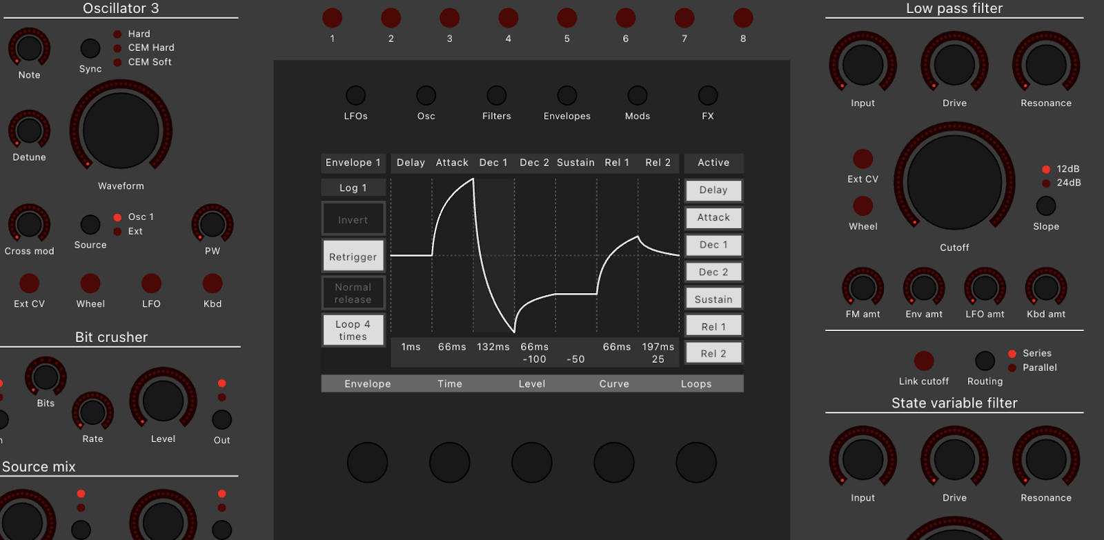
I can't remember if I've actually posted what the XM8 UI looks like?
I am doing a working midicontroller webapp that is at the same time a millimeter perfect SVG, this makes it possible for me to test the voice cards without having a physical controller, and at the same time decide on what the UI should look like.
Here is the first version:
I initially thought I would have an external screen/pad but decided that would be annoying, so the second version has a built-in 9 inch screen:Hah! Finally! I just discovered these:
https://www.globalsources.com/Rotary-potentiometer/Rotary-potentiometers-1148135774p.htm
It's a clone of the Alpha RV112FF-series endless pots, this one is by HongYu and named H111KGP+T4 360°Endless:
http://www.hongh.com/product/291.html
NB: HongYu also sells a non-360°Endless version named H111KGP+T4, so be sure to order the correct one!
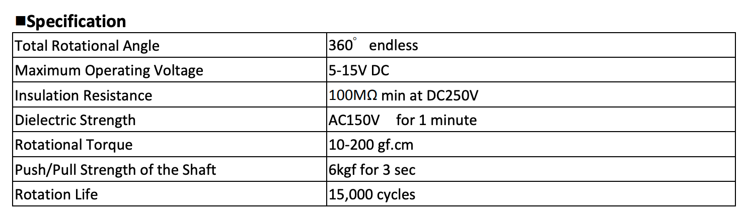
Here is the original RV112FF datasheet:
The specs are almost the same too, it's like they just copied the datasheet ;-)
| RV112FF |
| H111KGP+T4 360°Endless |
Here is a list of stuff that I've bought in large enough quantities:
ICs:
AS3364 - Quad lin VCA - 115
AS3320 - Filter - 45
AS3340 - VCO - 25
V2164 - quad exp VCA - 16
AS2164 - quad exp VCA - 20
DG412 - quad SPST - 100
DG413 - quad SPST/dual SPDT - 304
DG408 - 8:1 mux - 45
MAX7221 - LED driver - 32
DAC8565 - on breakout board, 20x.
Modules:
CEM3340 VCO - 20
DCO v1.4 - 40
Bitcrusher - 20
Quad exp VCA - 20
Quad exp Mixer - 20
Memory - 76
Reconstruction filter - 60
Button/caps:
Pushbutton, no click - SPH2N1 - 200
Pushbutton, click - SPH2S1 - 200
Caps, transparent black 8mm (round) - YCA080C - 100
Caps, ice dome shape 7.4mm - YCA044A - 100
Caps, snow dome shape 7.4mm - YCA044B - 100
Caps, ice flat 7.4mm - YCA043A - 100
Caps, transparent black flat 7.4mm - YCA043C - 100
Caps, transparent black 6mm - YCA045C - 100
Caps, transparent black 5mm (round) - YCA052C - 100
Caps, black 8.1mm - YCA0865 - 100
Caps, black 10mm (round) - YCA1115 - 100
Other parts:
Knobs 15 x 17, black, d-shaft - 500
Knobs 10.5 x 16, black, square hole - 100
Knobs 10.5 x 16, silver, square hole - 20
Knobs 24 x 15, silver, d-shaft - 15
Knob, 17 x 14, black, knurled shaft - 100
Alpha RV112FF-40-25A-0B20K, Endless pot, plastic shaft - 100
Alpha RV112FF-40B1-15F-0B20K, Endless pot, metal shaft - 150
Light pipe, 3 x 15.9, dome shaped - 100
Light pipe, 3 x 6, flat / rear insert - 100
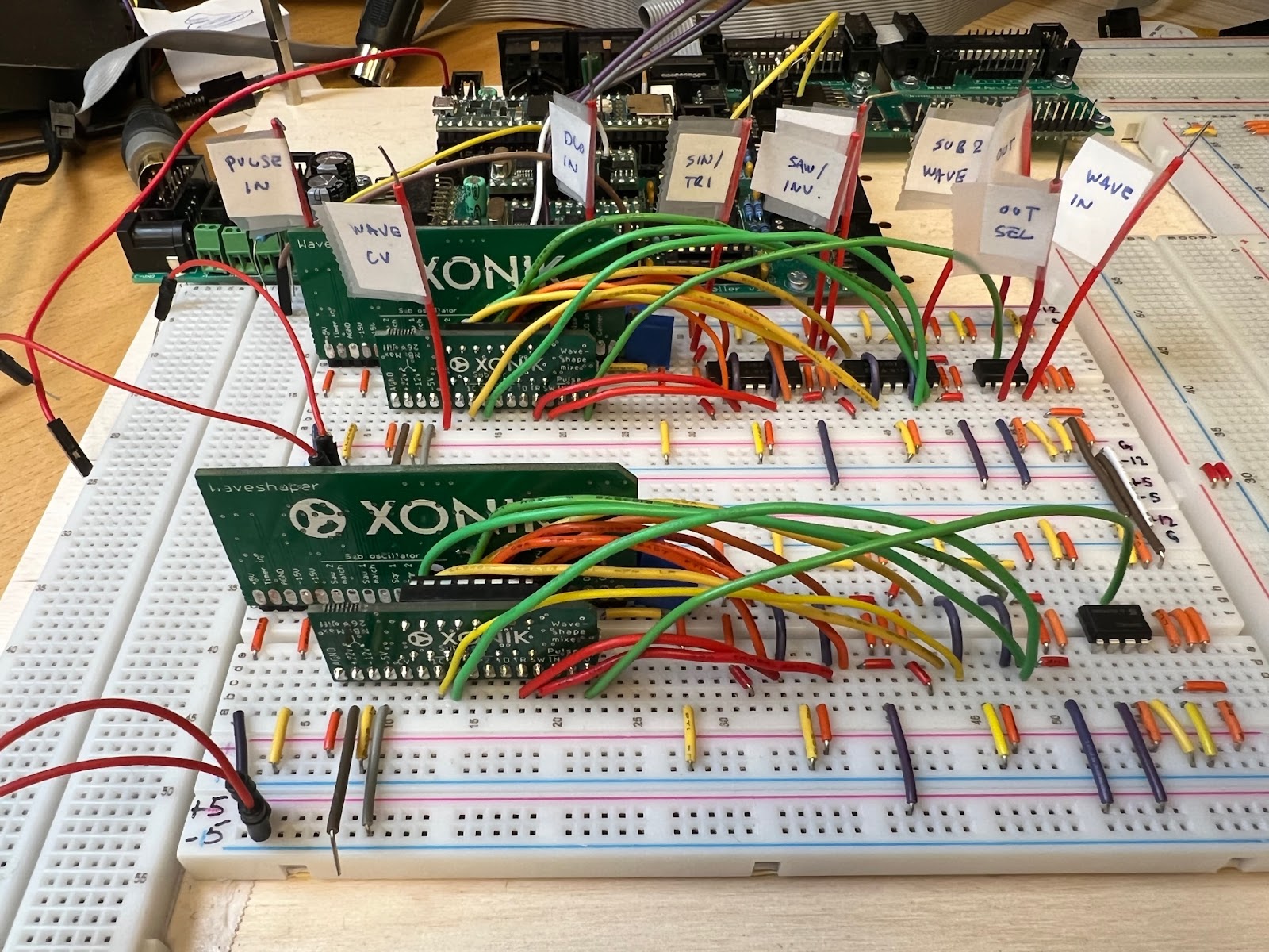
I redid both waveshapers today. It felt bad pulling apart the breadboarded circuits but in order to verify all fixes and test with full switching I had to do it. I don't have any DG413 switches yet so I can't test it, but I think it will work.
Now this is an interesting one. I have mostly completed the voice card layout - it is untested and will surely have a lot of adjustments before I route it and send it to production, but this is what I will base my breadboard testing on going forward.
PS: There are a lot of comments here and nothing is guaranteed to work!
Some quick facts:
I have yet to see if I can have both OTA and ladder filters. We'll see.
Anyway, here is the complete voice card - but without the controller and CV generation. When doing the real PCB I suspect the controller/CVs and DCOs will be placed on a separate board just as with the prototype controller, it works very well and keeps most fast moving digital signals away from the analog circuitry.
I always wonder what switch does what, so here it is:
Vishay also have switches with the DG3xx prefix (and others)
8p:
DG417: SPST normally closed
DG418: SPST normally open
Dg419: SPDT
16p:
DG401: 2 x SPST in DIL16
DG403: 2 x SPDT
Dg405: 2 x linked SPST
Dg408: 1:8 mux
DG409: 2 x Linked 1:4 mux
DG411: 4 switches, normally closed
DG412: 4 switches, normally open
DG413: 4 switches, 2 pos and 2 neg logic, May be used as SPDT/DPDT
NB: Max +/-8V men kan funke med single supply opp til 16v:
Dg4051: 1:8 mux
Dg4052: 2 x linked 1:4 mux
Dg4053: 3 x spdt
28p wide
Dg406: 1:16 mux
Dg407: 2 x Linked 1:8 mux
Dg445 - quad spst - what’s The catch?
Per the 12th of April 2022 I have:
2 x DG403 (dual SPDT)
2 x DG408 (1:8)
1 x DG409 (2 x 1:4)
5 x DG412 (4 x SPST)
1 x DG418 (SPST normally open)
8 x DG419 (SPDT)
Update
I ordered 306 Harris DG413 from Digikey as they were the cheapest I could find (around NOK 8.5). I also ordered 45 DG408 from Farnell, not as cheap, and will order 100 Intersil DG412 from Rs components (around NOK 8.5 too).
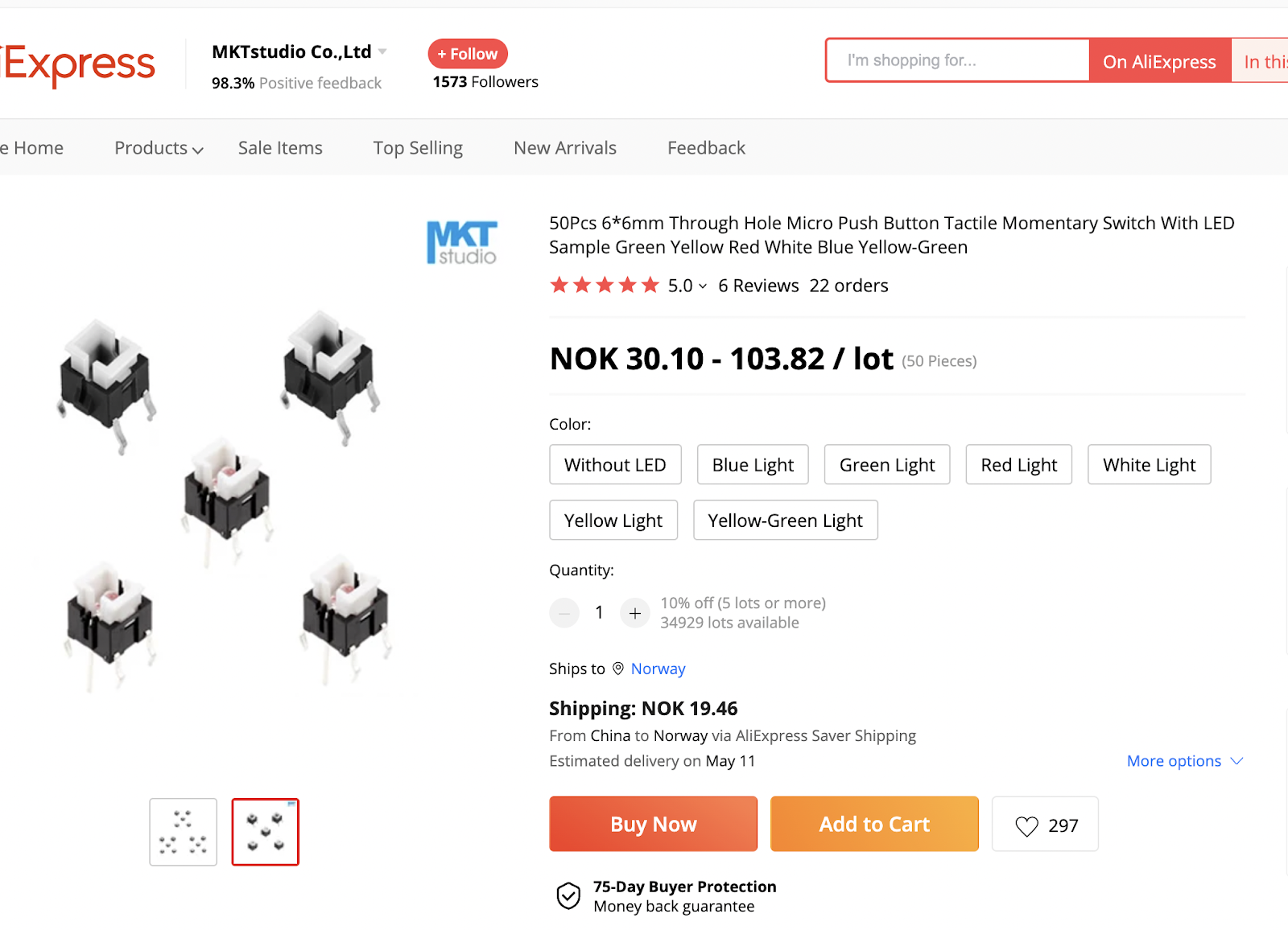
I stumbled upon a series of lit switches on Aliexpress. They look fairly similar to the ones I ordered from Shanpu.
The producer is Honyone, and they have a wide range of switches: http://www.honyone.com/en/products/class_7_1.html
The TS5 and TS6 series look very close to what I already have
https://www.aliexpress.com/item/4001350856334.html
https://www.aliexpress.com/item/33035513753.html
https://www.aliexpress.com/item/1005003600101230.html
https://www.aliexpress.com/item/32843003511.html