Saturday, March 22, 2014

New panels

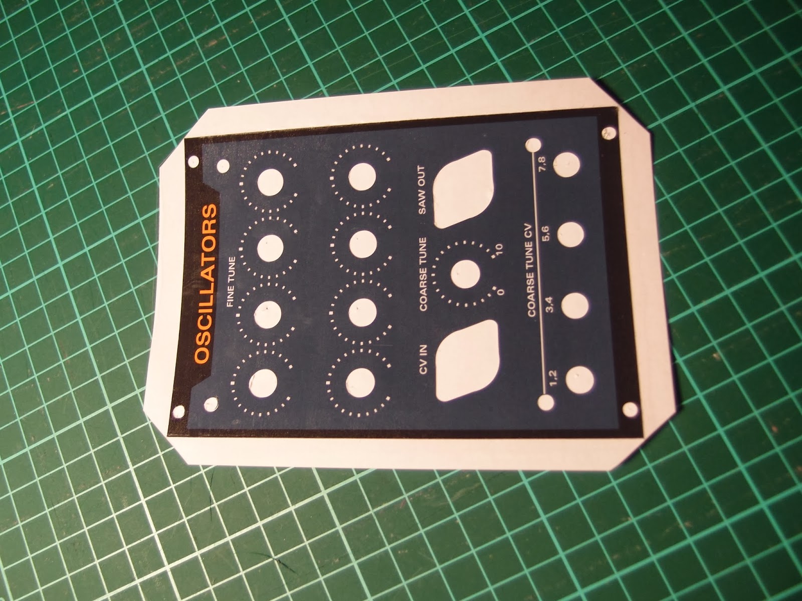
This week I've finished five new panels and prepared prints for three more. I've done two more oscillator panels, two sub oscillators and one 7-saw controller. I've also printed two more sub oscillators and one controller. Since the edges of the first oscillator panel didn't get as sharp as I wanted when folding the plastic around the edges, I've decided to cut the foil along the edges this time.
Plexi glass panels before attaching the adhesive film

Three oscillator modules - the first one to the left has plastic folded around the edges while the new ones are square cut for a sharper edge. I've also realized that I will run out of orange potmeter caps. Unfortunately, Re'an has stopped producing these so it's hard to get more. I've found some similar looking ones on Ebay, they seem to be 1mm wider but it may work out ok.
Finished sum oscillator and 7-saw control panels

Close-up of the sub oscillator. Note the input polarity switch, setting this to the opposite of the input wave will give that cool saw-within-saw wave shown in an earlier post

Tuesday, March 11, 2014

Tiny but crucial bug fix on the suboscillator board

A couple of weeks back I populated the first single suboscillator board, but much to my dismay it didn't work. I didn't have time to inspect it further, but I suspected it was related to the CD4013 flip flop as I had some trouble getting it to work originally. I ordered some more from a different source and they arrived yesterday.

I swapped the old chip for the new one, but it still didn't work. I then rebuilt the first part of the circuit on a breadboard, and it sort-of worked, but both flip flops in the package seemed to flip and flop at the same frequency, which they definitely shouldn't.

Today, I tried adding in a 2k2 resistor between the D and not-Q ports, as well as a 100nF cap from D to ground, a trick I found somewhere online when I originally designed the circuit. This made the circuit work again.

Doing this on the PCB would require me to cut some traces, which would be a lot of trouble, especially on the SMD-based quad suboscillator.

Luckily, when i replaced the 2k2 resistor with a wire, while leaving the cap in place, it still worked :) I soldered two caps onto the pcb as well, and it too worked like it should. I have not tried the board at various frequencies, but for the time being it seems to work fine.

While searching for solutions to my problem, I came across this post named "cd4013 weird shit" - that really sums up my thoughts about this whole problem too...

The fully populated sub oscillator board. It looks a bit like a bug of sorts, don't you think?

A closeup of the 100nF capacitor. Also note the beautiful curved cutouts, I just love the boards OSHPark are able to produce!

Tuesday, February 18, 2014

Final (?) Saw mix and detune circuit tested

This week I've spent at least 20 hours recalculating and building the saw mix and detune circuits on a solderless breadboard. I changed the mix and detune inputs to accept 0 to 10V instead of 0 to 5V, and also added an offset input to be able to use -5 to 5V inputs. The detune output still ranges from 0 to 5V, but the mixer slopes are now 0 to 10V as well, as this is what the VCAs I use expects.

I did a lot of up front calculations, but the final circuits were adjusted by ear. I am pretty pleased with the result, enough to go ahead and redraw the PCBs. I have decided to place the two VCAs on a separate, tiny PCB, which can be reused for other projects. I will also try to fit all parts on a single PCB instead of the two that the initial design uses, but this probably requires me to use SMD components again - the prototype uses almost 30 op amps and more than 50 resistors and takes up one and a half proto board :-)

The result is quite good, although not as good as I initially hoped and dreamed about. I am still impressed with the result though, especially at lower frequencies - it will make one hell of a bass sound. I may try to make a "computune"-style automatic tuner, to keep the oscillators better synced. I will also add a chorus, filter and perhaps distortion module, but for now I will focus on making the controller PCB.

The prototype fills two breadboards and includes all the necessary electronics for generating separate detune slopes for each oscillator, mixers to mix the single input pitch CV with the detune CV, mix CV slope generators, two VCAs and two audio mixers. To the right, behind the breadboard, is the 8 oscillator module.


Before protoboarding this circuit, i finished the 8 oscillator module, complete with separate fine tune pots and 8 CV in / 8 saw out connectors. It looks very cool!.

I shot a few videos for a friend of mine - the quality is crap but it illustrates how things work:


Sunday, January 5, 2014

Quad saw mixing

Before new years I tried hooking up a simple mixer to mix four saw waves. The mixer consisted of half of a TL072 and five 47k resisors.

While I DID get a mixed output, it sounded worse for every new oscillator I connected. Today I hooked up an oscilloscope to try to see if I could figure out what was going on, and in fact I quickly realized the problem.

When mixing two +/- 5V signals with unity gain, they will occasionally reach +/10V. Mixing three oscillators will result in +/-15V, and four results in +/-20V. The problem is of course that above 14.8V (or thereabouts), the op amp starts clipping, chopping of the tops. This does not sound very nice at all.

By reducing the gain resistor to 12k, the sum of the four oscillators will be within the original +/-5V. And indeed, the output sounds so much better! Now I'm closing in on the buzzing, swarming multi-saw sound I am looking for :-)

I have to rethink the oscillator mixer for the 7-saw though, to prevent clipping at all times. Next up is breadboarding the mixer again :-D

Wednesday, January 1, 2014

How to make cheap front panels

Due to our recent car purchase, I expect money to be a bit tighter than usual in the next months. I still need some cool front panels for my upcoming polyphonic/super saw synth. I have therefore been looking for ways to create decent panels at a low price instead of using Schaeffer/front panel express or similar services.

Today I completed the first prototype, a panel for the 8-saw oscillator, and this post explains the process in detail.

I have the luxury of co-owning a Silhouette Cameo cutter with my wife. This machine, while meant for scrapbooking and cutting vinyl for arts & crafts, works perfectly for cutting all sorts of soft materials. While you can get away with just an x-acto knife or similar, the machine makes the job so much easier and the end result much better.

Requirements

For the panels, you need the following:
- 2 mm thick perspex/plexiglass or similar hard plastic glass
- Adhesive-backed glossy photo paper
- Adhesive-backed transparent plastic

I got my perspex from Biltema here in Norway, but you can get similar stuff elsewhere. Make sure it is 2 mm, any more and you may not be able to attach the mini jack sockets, any less and the panel will bend too easily.

The photo paper I used is called Skyhorse Premium Quality Glossy Photo Paper, 130g, self-adhesive cast-coated. I got it off ebay in the UK. It is rather thick, and the ink I use (Canon CLI-55xx) is not absorbed well enough to protect it from wear and tear - it smudges easily even after drying for some time. This is however no problem as long as the paper is covered with the adhesive transparent plastic

The adhesive plastic I use is the kind used as a dust cover on books. It comes in glossy and matte finish, I've chosen the glossy one.

The process

Perspex

First I designed the panel in Illustrator. When doing this, I added cross hairs to all circular components, to tell me where to drill holes. When satisfied with the design, I made a copy of it and removed all but the outline and cross hairs. I then printed this design onto a piece of the adhesive photo paper, trimmed the edges using a paper cutter and attached it to the perspex. To make it easy to remove after drilling, I put the paper on top of the protective film that covered the perspex.

I then drilled all holes using a 1 mm drill bit in a drill press. It's much easier to get an accurately positioned hole using such a small bit first. Remember to also drill holes for any key tabs on the potentiometers.

Some of my holes are very close (1 mm) to the edge of the perspex. I drilled these first, in case they crack the perspex, so that as little work as possible is lost. Be very gentle and do not put a lot of pressure on the drill.

I then drilled 3 mm holes, even in those places where the end hole is supposed to be larger than that - still to get a better accuracy.

Then I used a conical drill bit to drill any holes larger than 10 mm. Finally, I drilled any remaining 6 and 7 mm holes.

After drilling all the holes I used a scroll saw to cut the edges and straightened them by sliding the panel along a metal file. This is the end result:

Cut and drilled perspex
Note that I tried to drill the holes for the potentiometer key tab only partially through the perspex. This was a bad decision as the plastic extrudes slightly, making the hole visible on the front even after attaching the photo paper. Had I drilled it all the way through, it would probably have been invisible.

Photo paper

After creating the raw perspex panel, I printed the panel design onto the adhesive photo paper.

The Silhouette cameo comes with a plugin for Illustrator that lets you add what is called registration marks to your drawing. Later, when you want to cut out parts of the design (holes for pots etc), the Cameo recognizes these registration marks and knows where the design is located on the paper. The plugin costs $40 but is well worth the money.

Panel design with registration marks in the corners
Next up is to cover the panel with the transparent plastic to increase its durability. I decided I wanted the edges to be well protected as well, so I came up with a way that let me put the plastic around the edges and onto the back. If you do not need this, just put plastic all over the panel and cut along the edges of the front panel (after creating holes for the pots etc).

In my case, I had to cut away parts of the photo paper around the edges of the panel so that the plastic film would not stick there. As the photo paper already has a non-stick backing paper, you only need to remove the photo paper itself. However, it is hard to cut through the top layer only, so I did instead cut all the way through:
Cut two grooves about 10 mm apart.
After cutting two grooves, I turned the paper over and put some Scotch magic tape over it to keep it in place. I then did the next side the same way etc:


Finally, I removed the photo paper from the parts I had cut out:


I could now cover the whole paper with plastic film:


 After covering the paper, I attached it to the cutting mat of the Silhouette Cameo:


Based on the same Illustrator design, I created outlines for the potmeter holes etc in the same position as the previously created cross hairs. I made sure to make the holes about 1 mm larger that the holes I drilled, as the silhouette is not accurate enough to get a perfect hit. The design is then sent to the machine and "printed" onto the panel. Due to the thickness of the plastic and paper combined, I had to set the cutting knife to 8, and even this proved to be a bit too little in some cases. Ideally you want to cut all the way through the photo paper but not through the backing paper.


I now carefully removed all the cut out parts using a sharp hook


Then I cut off the edges using a paper cutter. The corners are cut diagonally to be able to wrap them around the edges


Finally, I removed the panel from the backing paper and attached it to the perspex


After attaching the front panel components (knobs, jacks etc), all edges are covered and the result is quite pleasing. The plastic is slipping slightly from the photo paper close to the edges, this will probably not happen if you do not fold the plastic around to the back. Also, when tightening the DIN-jack sockets the plastic bulges slightly, this can possibly be prevented by cutting the plastic closer to the screw holes.


All in all I think the result is very good, especially considering the price and the time it took to create it. 

Monday, December 30, 2013

Quad saw revision 1.1

Following the debugging of the revision 1 board, I've updated the quad saw PCB. It now has a coarse tune input (oscillator 1+2 and 3+4 are tuned together) with the posibility to add a jumper wire directly to -15V if one does not want a coarse tune input.

I have also changed the power input to a four pin version that includes panel ground (Oakley Sound Systems-style) and turned all connectors 180 degrees.

Oh, and most importantly, the outline-corners have been rounded off ;-)


Sunday, December 29, 2013

Oh well - some errors are to be expected

While trying to tune the oscillators I discovered two errors. They are both easily fixable but important. First, I had used 100k instead of 10k pots for the wave balance pots, which means it was impossible to get a good balance around 0V. I replaced the pots and it worked very well.

Second, both this quad oscillator and my stock yusynth oscillator seemed to have a very high-pitched response to 0V CV. Only after reading through the text on the yusynth.net site did I realize that the coarse tune pot is not centered around 0. Instead, the maximum counter clockwise setting is 0 and the max clockwise setting is 10 (not sure if that means 10 octaves though). This means that in order to function "normally", I have to add a 270k resistor connected to -15V to my design as I have no coarse tune pot. It's not a big problem but one that will have to be adressed in a version 2 of the oscillator. I should also concider adding either an octave rotary switch or at the very least an octave/coarse tune input. As I have run out of space on the PCB, I think the pot will have to affect all oscillators, not only one, meaning all four oscillators will be tuned to the same range. Two four-oscillator cards could of course be tuned differently though. I may even be able to squeeze in two inputs so that groups of two oscillators may be tuned differently.

One final note: I have used 100k resistors for the wave amplitude amplifier input. Mr. Usson states that one may have to use an 82k resistor here and I can see why. My saw wave output has a +/-4V amplitude instead of the expected 5V, swapping the resistor may help.


UPDATE: Fixed!
Four 270k resistors soldered directly to the back of the board, with a common wire to -15V. The molten plastic gunk is clearly visible too. What a shame.

Saturday, December 28, 2013

Quad oscillator oscillating!

After a false start this morning, I managed to get my quad saw oscillator card up and running tonight. At first, it seemed like nothing worked, but after switching to another set of oscilloscope probes and probing from the start to the end of the circuit, it turned out it was working after all. Great success! :-D


The unpopulated PCB

My first ever try at soldering surface mountable components. It wasn't hard at all, just put some solder on one of the corner solder tabs (on the PCB), hold the part with SMD tweezers and solder the first corner. Then do the same to the diagonally opposite one. When they are done and the chip is adjusted to it's correct location the rest is easy.

The completed PCB. I tried cleaning the board with isopropanol, with disasterous results. The cleaning left white residue all over the card. In retrospect I suspect that the residue is in fact from the toothbrush I used for cleaning...


Oh... and to round up the post - of course an electronics enthusiast needs an electric car, so I bought this amazing vehicle, the Tesla Model S :-D It's a beast!

Two versions of the sub oscillator under production

Last night I sent two prototype versions of the sub oscillator for PCB production. The "normal" single sub oscillator with the cool inverted saw thing, as well as a stackable quad sub oscillator that can be used for my 7-saw/polyphonic modular project. The quad version will need a separate controller card as well, to be able to select the type of wave and polarity etc for eight sub oscillators at the time.

If successful, the single sub oscillator is destined to be the first official product from Xonik Devices, my new brand. All future projects will be released under this name.

Tuesday, November 26, 2013

Sub oscillator board finished

Last night I finished the initial version of a sub oscillator PCB. It is based on the circuit in the previous post, but since I had one flip flop to spare I've included a two-octave down square wave as well as a 25/75-duty cycle pulse wave, similar to (and heavily inspired by) the Roland SH-101. The kind of square wave to output is selectable by a three position switch.

The board measures 30 x 100 mm, with 3 mm screw holes 4 mm from all sides, and should fit behind a 6HP panel. Cut-outs have been added near the input, output and switch connectors, to be able to mount the board with the components facing backwards and then route the cables to the front without adding any width to the module. This makes it possible to adjust the saw wave matching trimmer after the PCB has been attached to the panel.

The board has a slight shortcoming related to the pulse output - since the average voltage over one cycle is not 0V, the centering capacitor will not center the wave around 0V but slightly lower. This has no effect on the sound of the output but may lead to unwanted effects/clipping in subsequent modules/when mixing waves. I have still provided the pulse output as an option because it only requires two additional parts and may be useful to someone.

Sunday, November 24, 2013

Updated saw suboscillator

I have been working a lot on the saw divider circuit lately. Last night i finalized a prototype that works for all audible input frequencies. It can also use both saw waves that start high and ramp down and the ones that start low and ramp up, as inputs.

The circuit has two outputs - saw and square wave, and the saw wave has two modes - frequency division and a more exotic one where the frequency is sort of both doubled and divided. Have a look at the pictures later to see what I'm talking about.


The divider works on the same principle as earlier, by shifting half of the saw teeth up and then reducing the amplitude back to +/-5V. However, it now uses fewer parts than my initial prototype and achieves more. Instead of using an offset voltage to center the wave around zero, it uses a capacitor to do the same thing. I've also added input and output buffers to the flip flop, and the rather complex voltage dividers used for the square wave have been replaced with a resistor ladder and an op amp buffer instead. The need for trimmer pots has been reduced to a single one, and all resistors are from the E12 standard values. The need for a RC-network between D and not Q of the flip flop also disappeared once I introduced the buffers.

The input is connected to a switchable inverting/non-inverting op amp buffer. The comparator used to make the initial square wave needs the input saw wave to ramp down to output the correct square wave necessary to generate a saw wave on the output. If your input wave ramps up instead, flip the buffer polarity switch. Running the "wrong" kind of saw wave through the comparator will lead to an interesting, useful and very nicely sounding output, so feel free to try both polarity settings independently of the input wave.

You may also use other input wave types. The output won't be a saw wave, but will have a frequency related to the input frequency, and be within the same amplitude range. Try it out!

In addition to the saw output, a square wave output with +/-4V amplitude is provided. This will work independently of the type of input wave (well, for "normal" waves anyway) and always have close to a 50/50 duty cycle.

The single 100k trimmer pot (I use a 20 turn one, but any multi turn will do) adjusts the matching of the two saw teeth that are combined to make the new half-frequency wave.

Output

These pictures show the various modes in real life. The scale in all pictures is 1 square vertically = 5V.

Saw wave

First, the saw wave output when the input is not inverted:

Input wave

Output wave, half frequency

Input and output shown at the same time

Inverted saw wave input

Then, the saw output when the input has been inverted (the input itself is the same but the invert switch has been flipped):

Input wave
Output wave - notice how it forms a crude saw wave of half the frequency but with the opposite phase as the input wave and made up of four small saw waves. It sounds great.
Input and output shown at the same time
The reason why we get the strange wave is that the square wave used to lift half of the input saw tops has been shifted 1/4th of a cycle, so instead of lifting a whole saw tooth, it lifts half of one and half of the next one.

Square wave

Finally, the square output. As a square wave is already generated to shift the saw up/down, making a square wave output is only a matter of scaling the amplitude to the correct +/-4V range:


Input wave
Output wave
Input and output shown at the same time

Sunday, October 6, 2013

Saw frequency divider

In my previous post I described how to make a frequency doubler for a saw wave. Now, more often synths have a frequency divider/sub oscillator. These are usually square wave oscillators, but I wanted one that would work with saw waves. After an initial idea and a lot of trial and error I have finally come up with a working circuit. It works on the same principle as the frequency doubler, i.e. it shifts parts of the wave up and down to achieve the saw form, but instead of cutting each sawtooth in half, it combines two teeth to make one with twice the duration.


The central idea - half of the teeth are shifted up to double the frequency


Dislaimer: Allthough I came up with the concept of this divider myself, I've since found that the core of the divider is quite common, even to the point that the good old Roland SH-101 uses the same trick - with the same 4013 flip flop :-D. I have yet to see a saw version though.

Some of the interfacing tricks are from Horowitz and Hill, and the RC combination to slow down the feedback in the flip flop are from a site elsewhere on the net (can't remember where right now),

Here is how the divider works:

1) The input saw wave is fed through an op amp set up as a comparator. This turns the +/-5V input saw wave into a +/-15V square wave, 15V whenever the saw wave is >0V and -15V when it is < 0V.
Saw wave is turned into a square wave by the comparator. Each vertical square equals 5V, so the saw wave is +/-5V and the square is +/-15V.


2) The signal is fed into a D-flip-flop. The internal protection diode in the flip flop chip chops off most of the negative voltage, so the Flip-flop sees a square wave of about 0-15V, in effect a clock signal.

3) The D-flip flop does the main work, and it works like this: Everytime the clock goes high, the value on the D input (0/1 e.g. 0 or 15V) is copied to the Q output. The inverse value is copied to the "not Q" output. The trick now is to connect the "not Q" output to the D input. In this mode, the Q will change state between 0 and 15 everytime the clock goes high. This means that it will take two input pulses to generate one output pulse, which means that the flip flop is a frequency divider, dividing by a factor two. In many synths the output from the flip flop is connected to a second flip flop to get a divide by four-frequency divider. This makes it possible to switch between 1 and 2 octave sub oscillation. In this circuit however, only the divide by two is used.
Input vs output of the flip flop.  Negative part of square wave is chopped off at the flip flop input. Notice how every high pulse on the input results in a change of the output. NB: The horizontal scale of this picture is half that of the previous one, so the input here are the SHORT pulses, the output are those with the same length as the ones in the previous picture. Also note that the small "ticks" in the middle of each horizontal line are because I forgot to ground the flip flop...


The flip flop output compared with the input saw wave. The square wave is positive for every second saw tooth, i.e. has half the frequency 


4) Now we have to turn the square wave with half the frequency back into a saw wave. Like with the frequency doubler we achieve this by combining the original signal with the square wave. But instead of shifting parts of the original wave closer to the 0 volt line to spit it in two, we shift then further apart to combine two saw teeth.

5) Before combining though, we have to adjust the amplitude of both the original saw wave and the square wave to keep the result within a 10v p.p. range. Also, because the square wave is not centered around 0V (unlike the square wave used in the frequency doubler), we have to add an offset voltage. The outputs of the three operations are summed to give the resulting half-frequency saw wave


Original saw wave

Resulting saw wave. The spikes half way through the wave are presumably caused by the spike at the start of each wave, though this has not been confirmed

The two waves compared. It sounds great!


The circuit looks like this:
Notice: The square wave in the top right corner is wrong, it should start at -5V, not 0V.


A few things to note about the circuit:
1) The 12k resistor between the comparator and the flip flop limits the flow of current into the chip as it can only handle about 10mA of input current. (page 578, Horowitz and Hill)

2) A 2k2 resistor and 100nF capacitor has been connected between the "not Q" and D ports of the flip flop, to delay the signal between the ports slightly. Without these I could not get my flip flop working. I find this a bit odd since other designs usually do not have these.

3) The output from the flip flop is buffered by an op amp in buffer configuration before it is used in other parts of the circuit.

4) Like the frequency doubler, the next stage is an attenuator (amplifier with gain < 1), found here. It turns the 0-15V square wave from the flip flop into a -5-0V square wave. NB: The wave is inverted, +15V turns into -5V.

5) the same thing is done with the saw input, it is attenuated from a +/-5V wave to a +/- 2.5V wave. Summing the square wave and the saw wave will result in an output with a 10V p.p swing, just like the input signal.

6) However, the signal goes from +2.5V to -7.5V. To adjust the symmetry back to +/-5V, we add a DC voltage of 2.5V, which comes from the 100k potentiometer and is buffered by yet another op amp buffer.

There are a few issues about the circuit though, and it should not be considered final.

1) First of all, because of the 12k resistor after the comparator, the input to the flip flop has a slow slew rate, which is a problem at high frequencies. I started seeing (and hearing) problems due to this at input frequencies > 10kHz. Using two MOSFET transistors for interfacing may solve this, I have not tried that yet.

2) The comparator may "bounce" when crossing 0V (i.e. going between +/-15V very fast), which will lead to multiple clock pulses going into the flip flop. This can be solved either by setting up a hysteresis configuration, using a comparator with built in hysteresis or passing the signal into a CMOS buffer with built-in schmitt trigger before the flip flop.

3) Likewise, the output from the flip flop may be connected to another CMOS buffer like the 4050, this may remove the need for the op amp buffer (I have not tried this yet - see page 586 in H & H).

Thursday, September 12, 2013

Saw wave frequency doubler

After listening to Grant Falkenburg's demo of the JP8000 on youtube, I realized that it would be cool to have the option to add a secondary wave to the output of the super saw oscillators, one octave lower than the original frequency.

This got me thinking about how to create a frequency divider, which in turn led me to come up with a way to create a frequency doubler as well.

I have dreamt up both the divider and the doubler, but only the doubler has been breadboarded and tested. My initial design was revised a few times and the current design seems to work fairly well for frequencies up to at least 5kHz, and looks ok but with a little bit distorted output all the way up to at least 10kHz. I don't think frequencies above 10kHz are all that interesting as the doubled frequency (20kHz) is starting to push the limits of human hearing.

In any case, I have yet to actually listen to the result, I have only watched it on my oscilloscope. I also do not currently have a saw wave source (Well, I actually do, but my function generator cannot output saw waves and I cannot be bothered connecting the little phatty to the circuit) so I tested the circuit using a triangle wave instead. The end result should be pretty similar though.

The idea of the circuit is to detect when the original saw wave crosses 0V. This is done using an opamp in a comparator configuration, which will output a constant negative voltage slightly less than the negative supply voltage when the input wave is > 0V and a constant positive voltage slightly less than the positive supply voltage when the output is negative. The output is then scaled down to half the amplitude of the input wave. By summing the two and amplifying by 2, the result is a saw wave with double the frequency and the same amplitude as the input.

This picture shows the input wave (triangle) and the resulting square wave output by the comparator (after scaling to 50% of the input amplitude):


Here is a drawing of the circuit. The potmeter across the second op amp adjusts the attenuation of the comparator output which in turn adjusts the symmetry of the two parts of the output wave. With a 10v p/p input wave and a supply voltage of +/- 15V, the attenuation should be about 1/6 (giving the square wave output from the comparator a swing from -2.5 to 2.5 volts). As opamps cannot really handle a gain of less than 1 when in the normal inverting mode, a 8.2K resistor is connected to gnd (see this page for a detailed explanation):


The breadboarded circuit is really tiny:

One thing to be aware of is that the output of the circuit is inverted with relation to the input wave. This can be corrected by using the last opamp of the TL074 as an inverting amplifier with unity gain to invert the result back.

Here is a photo of the result at around 1-3kHz:
Inside the red square you can see both the input waves and the resulting wave with the doubled frequency. Notice that both parts of the new wave have the same starting voltage and the same amplitude as the original wave (one square on the scope equals 5V).


This photo shows the result at around 10kHz:
As you can see, the starting point of the second part of the output wave is higher than the first part. Also, the fall from the top of the first part to the bottom of the second part is not instant, it is slightly slanted (This is of course also the case for the 1kHz wave but it is not visible as the scale is different).

The reason for both these errors is that the rise time of the square wave output from the comparator is a little bit too slow. I doubt that it will be a big problem at this frequency. At higher frequencies the problem becomes more and more pronounced, but as mentioned earlier I do not expect the circuit to be used above 10kHz anyway.

Next up is the frequency divider, but to build that I need a flip flop.