Showing posts with label frequency analyzer. Show all posts

Monday, July 7, 2025

Debugging VCO Pitch unstability continued 4 - selected solution

I've officially come to the conclusion that I'm not able to make the noise level any better at the moment. I've ended up at a point where the noise is at around +/-3-5 cents as measured at the VCO frequency. I'll list some of the things I've tried and what my selected solution is.

What causes the noise

The main parts of the noise seems to be caused by the current running through the transistor collector and to ground. The noise follows the pulse width. When the pulse VCA CV is turned down, the noise is reduced, from +/-14 to 3 cents. 

1k collector resistor, massive noise on VCO, and it follows the pulse wave (top)

 
With pulse VCA at 0, the noise is reduced

By increasing the collector resistor from 1k to 47k, the noise is greatly reduced. The noise is still present even if the pulse wave VCA CV is turned down, but when replacing the 1k resistor with a 47k one, the noise with CV at max and CV at min are the same. I did a lot of experimenting trying to get it even lower, but nothing helped. The rest of this noise presumably comes from other parts of the waveshaper, see "Residual noise" below.

47k collector resistor, vca at max. Almost same noise level as when vca is at 0. Still traces of noise that corresponds (inversely) with the pulse wave.


Unfortunately, replacing the 1k resistor introduces switching noise. The switching noise is visible on the waveshaper output for other waveforms, though it isn't audible. As waveshaper output is mixed before the oscillator VCA, when the oscillator volume is turned down, the switching noise to signal ratio is kept and switching noise doesn't get any worse. Rise time for the square wave doesn't significantly change with higher value resistors.


Switching peaks with VCA at 0 and a 22k collector resistor

Tiny notch on the bottom of the sine wave, it moves with changes in pulse width.


The switching noise may be decreased by introducing a cap from base to ground or collector to ground. 100p and 470p caps have been tried and work well, but they also change the pulse width at high frequencies (because they slow down the switching time) which may be a problem.

100pF cap from base to ground, pulse with is narrowed.


What is NOT causing the main part of the noise

- The op amp comparator part, neither for the square wave or the sub oscillator 

- The switching spikes - no change is seen when introducing caps to prevent switching spikes.

- Moving ground to star ground does not help 

- Removing square wave probe doesn't help, so noise is not propagated by the logic probes.

- Increasing cap on the output doesn't help


What is causing the residual noise (the parts in sync with the DCO)

- Disabling the transistor by connecting the resistor base resistor to ground (some)

- Disabling the square comparator by disconnecting the saw (better)

- Disabling the whole waveshaper by disconnecting the saw from the input (best)  

But all in all, even with the saw input disconnected, we still get variations around +/-3 cents, though no longer in sync with the saw/square wave, so hard to tell really

Lowering the Pulse VCA CV did not change anything, so a lower initial pulse amplitude won't fix it. 

Switching noise

- Increases when collector resistance increases

- Top is only visible when pulse VCA is low

- Cap at base or collector to gnd helps but rounds off pulse and changes pulse width due to slower transition

- Using resistor divider before base helps, but increases the main noise, even when resistor divider is 100k/22k to gnd, with base at center. (Juno 6 does this). Divider doesn't have to be buffered

- Most of the peak is filtered out by the output cap (3p). Increasing the cap works but rounds off the square wave. May not be audible because cutoff is fairly high, around 200kHz with 3p/270k.

- Increasing base to 150k from 68k doesn't help


Other

- Had some smaller noise peaks on the output. A separate wire from mainboard to waveshaper for DCO saw input removed it. 

- a 50Hz noise was visible, possibly mains related 

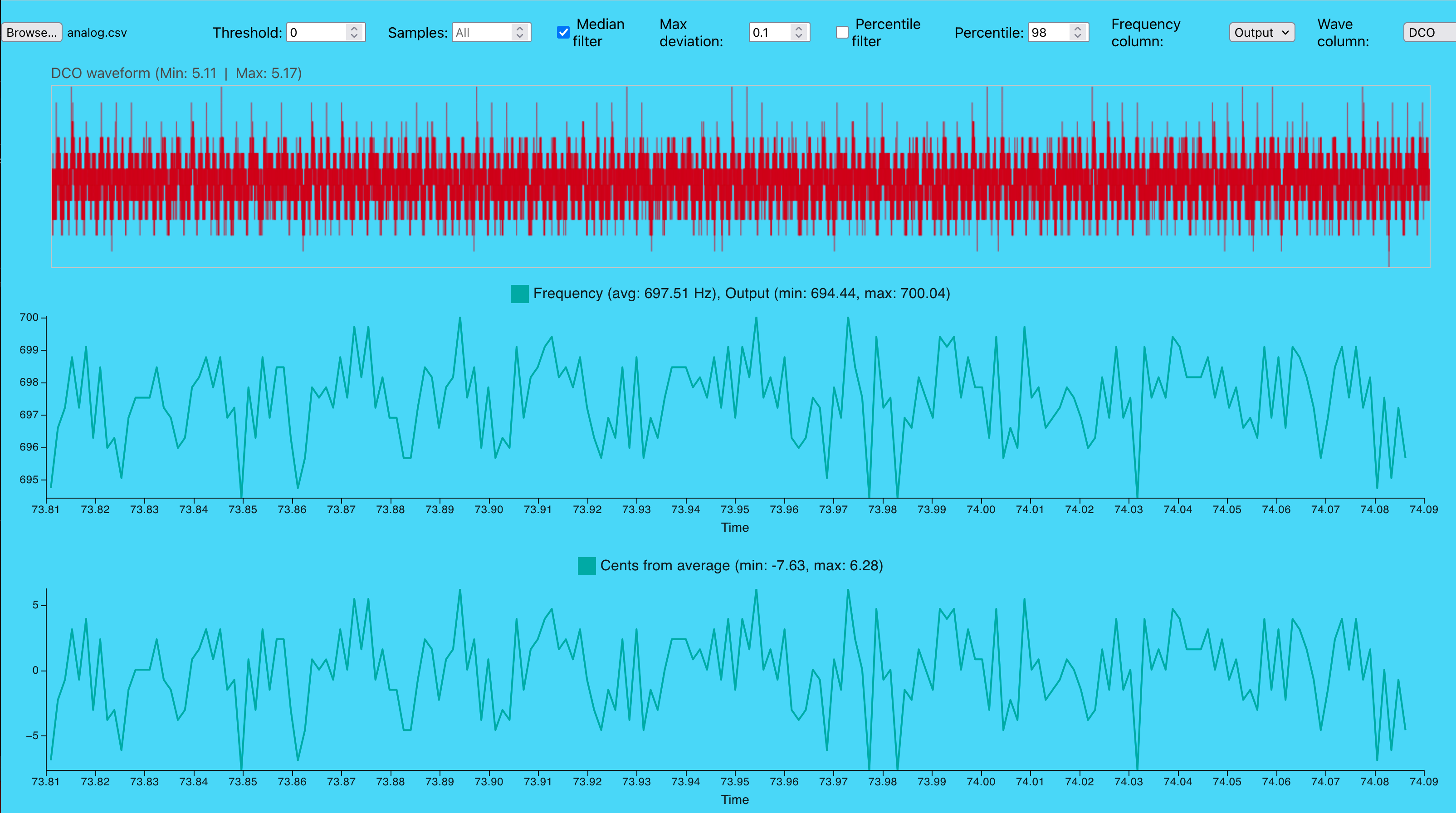
 - It's hard to measure the noise. After updating the frequency analyzer script to show a filtered version, the cents calculations seem to have increased, so I've mainly looked at how much the noise follows the square wave. 

- PW: A bit unstable measurements - with 2.63V CV, PW at 47k is 37%. For 1k I first got 22% but then a second, restarted MCU measurement gave 34%. I think in reality the PW stays about the same (with the same output gain resistors etc, set for a correct output with the 47k resistor). The pulse width stays constant when increasing square wave from 330Hz to 8.1kHz, which means this is easily tuneable anyway.

New circuit

- 47k collector resistor 

- 68k base resistor

- 220k+33k resistor from pulse VCA CV to op amp (moves center to compensate for increased collector resistor)

- 270k feedback resistor (increases gain)

- Optional 100p-470p cap on base-gnd 

Other things to consider

- Two CV inputs on VCO to get a better CV level/less noise sensitive

- NB: Must also update square wave generator ON VCO BOARD! 


Update 

I tried a few more things. Moving the VCO off board, and connecting the VCO pitch CV to the CV on my modular. When running without the digital power on on the XM8 (meaning no DCOs and waveshapers running), I get a fairly clean signal - but with a 50Hz component (mains probably):


When I turn on digital again, I get more noise:

I've tried connecting the Linear FM back to the main XM8 board. I got no more noise (with FM disabled) but cannot test further as OSC B does not get through to the FM input because the waveshaper is missing.

Connecting the Exp FM to the mainboard introduced massive noise since the pin on the VCO board is at the summing point of the input op amp, meaning the long leads introduce noise. 


Saturday, June 14, 2025

Debugging VCO Pitch unstability continued 3

Aaaaand testing continues. NB: Most measurements are now with the VCO connected to power ground.

Reducing pw to 25% to see if it affects the noise

The noise clearly follows the DCO even when pw changes, meaning it is highly likely that a lot of the noise comes from the pulse wave generation. It is a bit delayed/rounded off though.

Turning up DCO at mixer VCO to see if noise increases

It doesn't look like it affects the noise notably

Turning up square sub oscillators 1 and 2 


It's a bit hard to tell, but it looks like the noise drops whenever the pulse wave drops, even if the output from the waveform mixer has the sub oscillator cancelling out every second drop.
With a longer sample time however, we can see that it looks like the noise rises to a higher level when the mixed signal rises too. Not quite sure how to interpret it but it does seem like the sub oscillator has some effect on the noise.

Removing the mixer pcb

Noise is highly visible even if no waveforms reach the output

Trying to measure noise on the pitch CV 

It's a bit hard to measure the noise. There are huge spikes during SPI traffic, but this is probably due to crosstalk within the Logic Pro. 

Measuring again without SPI probes (those are needed at the moment for stable 50MHz SPI)

Much better, the SPI noise is mostly gone. As a side note, the CVs become unstable as the DAC sees wrong values, for example the VCA CVs for the DCOs (probably):


Comparing DCO output and Pitch CV (with SPI probes on):

Markers 0, 1, 2, 3 are at the start of the DCO edges. It is possible to see that the noise in the pitch CV follows (albeit slightly delayed) the same pattern.

Removing the SPI probes

The stepepd noise becomes more visible. It is clearly there still (though - is it there or is it on the ground of the Logic Pro? Nobody knows!

Zooming in on the CV noise

The CV noise seems to jump up and down approximately 10mV. If run through a 39k resistor, it will have the same effect as 100k/39k = 2.56*10mV =26mV would have on a 100k input (e.g. a 1V/oct input). One octave is 1200 cents, so this should result in a noise of about 31cents pole to pole. This matches well with what we see.

Still, I am not sure exactly WHERE the noise is

Moving VCO GND back to the mainboard. 

Connecting the ground of the Logic Pro to the GND on the VCO, measuring pitch CV at input to mainboard to measure more accurately what the VCO sees. Presumably, since the pitch CV summer is ground referenced, the difference between the CV and GND at this point is what the VCO sees - whether it is the CV or the GND that carries the noise. The 10mV difference is still there.

Controlling that the probes measures a silent GND

The CV probe and probe GND is now connected where the GND is tapped for the CV board. Strangely, we still see the DCO. This may be crosstalk in the Logic Pro though.

Disconnecting the output probe

This is weird, we can still slightly see the DCO but definitely not as clearly

Disconnect probes from the filter (!)

I've had probes connected to the JP6 filter the whole time (whoops). Disconnecting them changed nothing though, or not for the better at least.

Disconnecting the SPI probes again

Smaller variation but still periodic noise.

Reconnecting SPI, tapping GND and CV from same probe pair 

Did the noise go away? It's hard to tell. It does look less noisy though. We're up against the limits of what the Logic Pro can measure but it looks like using the ground probe from the same pair is a good idea.

I'd say the ground measurements are inconclusive. There is definitely noise there but I can't figure out where it gets into the measurements.

Using CV generated by my modular


The CV generated externally looks clean. It has a lot of noise, but it doesn't seem to be periodical

Using CV from modular to control VCO

Now, this was surprising! This is the worst noise so far, +/-40 cents. Perhaps the VCO VC and VCO GND both contain parts of the same noise, but of inverse phase, so it partially cancels out? 

Revert to normal but disconnect linear FM

Back to the 'normal' noise again (20 cents this time, but remember that we moved the VCO ground)

Connecting both waveshapers and VCO to power ground 


 This is also a bit interesting. The max noise is not reduced (sttill around 20/20), but there is a second signal bleeding through, modulating the noise at 7-8 times the DCO (between 2330 and 2660Hz). Also, at the negative going poles there are half the peaks. What is going on here, is this some sort of self modulation? 


Conclusion

We're really not that much closer to a solution here. 

Star ground from power may not be helping as other parts of the circuit will reference the noisy ground and that may even result in a higher noise since none of it cancels out. 

The noise seems to mostly follow the pulse wave, though something else may also affect it

I am inconclusive as to where the noise propagates. The one thing I haven't checked is the power lines

Noise and crosstalk on probes seem to mess with the result (and especially disconnecting the SPI probes has a great effect) though I don't think this affects the frequency modulating noise, just the measurements of noise on a signal/gnd line. The frequency modulation is still the best way to see what the VCO actually experiences.

Next

The most important thing left to try is rebuilding the comparator parts of the waveshaper, remove the original waveshapers and see if the noise is still there. If it is, we can try to isolate the noise, and if we manage to do that, try to improve it.  

Wednesday, June 11, 2025

Debugging VCO Pitch unstability continued

With PW set to zero

This mostly removes the noise. Not completely, but quite a lot better

With triangle DCO

The frequency seems to vary with the triangle wave as well
 
But when increasing the resolution and VCO frequency, we see that it is not a complete triangle, it seems to drop abruptly at the top of each DCO cycle.

Square wave is rounded


An observation - the frequency square wave is rounded, almost like it is low pass filtered.

Removing waveform mixer VCA

The square wave has its VCA on the waveshaper board so it is still visible  

Setting DCO to triangle, waveform mixer VCA is still removed

The triangle wave now never reaches the waveform mixer, but the square wave still breaks through. The frequency variations are almost exactly the same as what we saw when the triangle wave WAS connected, see "with triangle DCO, high resolution" above. Perhaps the triangle does in fact NOT affect the CVO.

Setting DCO to square, PW to 0. Waveform mixer VCA is still removed


There is still a small variation, but it is less than we saw before. However, there IS a slight up and down squarish effect here. Could it be coming from the input to the sub oscillator flip flop?

Also, there are significant spikes at the period marks. It could be that a PW of 0 is not quite turned off OR it could be from the sub oscillator circuit.

Moving waveshaper off board with jumper cables

The noise is the same as previously, distance doesn't matter

 Single DCO set to triangle

Square still breaks through

Pulse output from waveshaper board disconnected 

This is very interesting, almost not understandable. The pulse output is disconnected so the pulse wave does not reach the mainboard. But still we see the frequency noise! We also see the clicks on DCO period start.

Disconnecting the DCO input

Disconnecting the DCO from the waveshaper makes everyhing go away. Not surprising but a nice check. 

Recap

So, what we see this time is that 

- The noise is most likely only caused by the pulse wave (?), or at least not as much by triangle etc.
- The noise is present even when the pulse wave is disconnected from the mainboard
- There are heavy spikes at the start of each cycle

Theories

- The noise may originate from two sources: The saw-to-clock-pulse converter around  IC6 (LM311), and the pulse wave generator around IC1
- The noise does not travel (exclusively at least) through the pulse pin. 

Next up

- Disconnecting other waveform pins
- Disconnecting sub oscillator pins
- Disconnecting trimmer pots, replace with resistors
- Stopping the sub oscillator, with and without pw at 0
- Halving the DCO input to completely stop PW output
- Moving GND pin for the waveshaper to not return to the mainboard
- Check if flipflop stops
- Reconnect everything and move GND only.
- Move VCO offboard and do stuff suggested in the previous post. 

Tuesday, June 10, 2025

Debugging VCO Pitch unstability

After making the frequency analyzer script, I've started a thorough checking of the VCO frequency. It's very clear that something is not quite right, something is modulating the CV (e.g. some kind of noise on the pitch CV input, or perhaps ground).

I initially thought that the linear and exponential FM inputs could be the culprits, so I removed IC9. Here is what that looked like:

The frequency very clearly oscillates around 653Hz. However, don't get fooled by the sinusoid or triangle looking shape - the frequency variations are bipolar, they go in both positive and negative direction. If the noise was indeed a single sine wave, it would not bounce up and down. (Now, this may actually be wrong, see later in the post).

That probably means that we're dealing with more than one noise source, that sometimes cancel out and sometimes doesn't. Almost looks like two oscillators slightly detuned, right? 

Increasing the VCO frequency gives us a better view of what is going on:

With a 7.3kHz wave we get a better approximation of the noise. We get several samples at the same frequency (the small peaks are probably due to the sample rate in logic2 being too low), then it drops and stays low for some time, before going up again. It doesn't take too much imagination to see that the noise may be a square wave of some sort.

If one looks closer at the timeline, the pulses appear to be around 0.003s apart, meaning the noise has a frequency of around 333Hz. 

Now, where on the board can we find two square wave sources, slightly detuned? I got a feeling, let's have a look at the output of the DCOs!


 Oh yeah! The DCO is currently running at 330Hz! 

Lets double check. What happens if we halve the DCO frequency?


Ok, the issue isn't as pronounced now, it's dropped from +/-20cents to +/-10 cents - but the period has changed to 0.006s, the noise frequency is now 167Hz. I think it's pretty clear that this it DCO related.
 

Chasing the source

Clearly, the source is related to the DCOs, but what exactly? Is it 
- the DCOs themselves
- the sub oscillator circuit (that made audible noise in the previous waveshaper version!)
- the square wave generator
- the output from the waveshaper 
- the output from the waveform mixer

Here are some things I've tried:

Changing the waveform of the DCOs from square to saw:

There is still considerable noise, but the square wave pattern is gone. 

Disconnecting the waveshaper PCB: 

Now the noise is nearly gone! most fluctuations is reduced from 20 to 2 cents, which is probably an acceptable level. Also, putting back the IC9 FM source switch didn't change anything, which is hardly surprising since the FM sources are gone...

Reintroducing the waveshaper, but removing the DCO inputs:

Still looking good. Again, not surprising but at least it tells us that the waveshaper board by itself doesn't cause the noise.

Reintroducing the DCO inputs, one at the time:


DCO A

DCO B

Now, these confuse me. With a single DCO we still get a sine-like behaviour. Looking at DCO A, the VCO frequency (662Hz) is very close to twice the DCO frequency (330Hz), so two and two cycles are probably getting modulated by each top/bottom of the DCO wave, and as the frequencies are not exactly the same, the time at top/bottom moves around, creating the sine/triangle effect?

The DCO B plot is completely bonkers, bot sure what is going on there. The difference in cents is still 10 though. 


More to test

- Remove the waveform mixer. If the noise is coming from the waveshaper itself it shouldn't matter (though, as changing the DCO waveform DID matter, I suspect that this doesn't change anything).

- Short the suboscillator flip flop input to ground to stop it. Will tell us if the sub oscillator is the source. NB: Test with a single waveshaper.

- Change the pulse width of the DCO pulse wave, if possible disabling the pulse wave altogether. This is also best tested with a single waveshaper, just disconnect the second DCO input. NB: Test with different waveforms selected, not just pulse. 


Now, after these tests we should have a fairly clear view of what the noise source is. Next up is figuring out how the noise enters the VCO. A few things to try:

- Move the VCO off board and connect the pitch input to ground close to the PSU

- Move the VCO off board and connect the ground input to ground close to the PSU  

- Try to measure GND and pitch CV at the VCO input relative to GND at the PSU 


A note on noise amplitude

The frequency analyzer predicts the noise amplitude using the ratio cents to volts. In a 1V/octave, 1V corresponds to 1200 cents. The change is linear (well, if the VCO tracking is tuned properly), so 20 cents means 16.7mV.  

The VCO circuit is currently 1V/oct if using a 100k resistor at the input. This is true for the exponential FM input, but for the pitch CV we're using a 39k input. In this case, 1V is 2.56 octaves or approximately 3000 cents. 20 cents will then be as little as 6.7mV!

On the other hand, if the noise is coming through the ground plane, who knows what the amplitude will be.